

Fly Ash Facts for Highway Engineers
Chapter 6 - Fly Ash in Structural Fills/Embankments
Introduction
Specifications for fly ash structural fills and embankments are similar to specifications for engineered soil fills. Proper placement and compaction of fly ash fills is required to achieve the desired strength and compressibility characteristics assumed for design.
Figure 6-1: Highway embankment with fly ash structural fill.

Design and Specification Requirements
Ash sources. Fly ash for structural fill applications can be obtained as conditioned fly ash from a silo or as ponded fly ash from a pond or a stockpile. Silo fly ash can be delivered with close controls on moisture content and grain size distribution. Conversely, the moisture content or grain size distribution of ponded or stockpiled ash can vary considerably depending upon its location within the pond or stockpile. Therefore, using ponded or stockpiled ash may require several series of laboratory tests. If fly ash from more than one source is being used on the project at the same time, it is preferable to place and compact the ashes separately. Because of its self-hardening properties, high calcium ash is typically stored dry in silos and hauled to the construction site in pneumatic tank trucks, or is removed from a pond or temporary stockpile. This procedure may not be necessary if the site is close enough to the plant to allow the ash to be hauled in the moistened condition.
Site conditions. As with any embankment project, standard geotechnical techniques are used to evaluate subsurface soil and groundwater conditions. The two most important subsurface characteristics affecting embankment construction and performance are shear strength and compressibility of the foundation soils. ASTM E 1861 provides additional guidance concerning technical and environmental considerations.
Physical, engineering, and chemical properties of the ash. The physical and engineering properties of fly ash that will determine the behavior of the embankment are grain-size distribution, moisture-density relationships, shear strength, compressibility, permeability, capillarity, and frost susceptibility. Laboratory tests designed for testing soil properties may be applied to testing fly ash. The chemical characteristics of the fly ash affect the physical behavior as well as the quality of the leachate produced by the ash. The utility company or its marketing agent can provide information on the physical, engineering, and chemical composition of the ash and leachate characteristics.
Design issues. The mechanical behavior and compaction characteristics of fly ash are generally similar to those of silt. For this reason, fly ash also shares some of the difficulties that are characteristic of silt such as dusting, erosion and frost susceptibility. These difficulties can be properly addressed during the design of the embankment. For example, ice lenses grow in silt-sized soils by wicking water up from a shallow groundwater table. Such ice lenses expand during the winter and melt during the spring causing unstable and soft embankment conditions. The problem can be avoided by controlling upward seepage with a layer of coarse-grained material or geotextile at the base of the embankment. In general, avoid using fly ash as a fill material below the groundwater table or when the embankment design cannot provide adequate drainage.
Environmental impacts. The trace element concentrations in many fly ashes are similar to those found in naturally occurring soils. Although the leachates of some fly ashes may contain trace element concentrations that exceed drinking water quality standards, this is also true of certain soils. State environmental regulatory agencies can guide you through applicable test procedures and water quality standards. The amount of leachate produced can be controlled by assuring adequate compaction, grading to promote surface runoff, and daily proof-rolling of the finished subgrade to impede infiltration. When construction is finished, a properly seeded soil cover will reduce infiltration. For highway embankments, the pavement may be an effective barrier to infiltration.
Erosion and dust control. To prevent wind and surface water erosion of the fly ash embankment, use the same sediment and erosion control techniques common during earthwork operations. This includes wetting down exposed surfaces and installing silt fences or straw bales around construction areas. Dusting will likely occur when compacted fly ash is placed in dry, windy, or freezing weather, or during traffic disturbance. During construction, the surface should be kept moist, covered, or stabilized with lime or bitumen. To prevent erosion and dusting after completion of the embankment, protect the fly ash with topsoil and vegetation or by sealing with bituminous emulsion.
Specifications/quality control. There are two types of specifications used for the construction of fly ash embankments: performance specifications and method specifications. The construction quality control effort required depends greatly on the selected specification approach. Additional information on specifications and procedures can be found in ASTM E 1861.
Performance specifications. Performance specifications designate the required degree of compaction and the allowable moisture content range. For road embankments, a typical requirement is to compact the fly ash to 95 to 100 percent of maximum dry density, as determined by AASHTO T 99 (ASTM D 698). The allowable range for the moisture content is determined by plotting the laboratory moisture-density relationship. Figure 6-2 shows the dry density and moisture content relationship. Fly ash may be variable enough that several curves are required. It is preferable to place the ash at less than optimum moisture because it will be difficult to impossible to obtain compaction above optimum moisture contents.
Figure 6-2: Allowable moisture content range below optimum moisture content
Method specifications. On some projects, method specifications are preferable over performance specifications. The method specification is based on the results of field compaction tests on trial strips. The required lift thickness, weight of compaction equipment, speed of compaction equipment, and the number of passes are thus specified so that the necessary degree of compaction is achieved. If vibratory compaction equipment is being used, the resonant frequency of each compactor in use is also established in the field. The method specification allows for simpler quality control because the compaction procedures can be monitored visually. Compactive efforts to achieve 95 percent of the standard proctor maximum dry density are shown in Table 6-1.
| Equipment | Thickness | Passes | Comments |
|---|---|---|---|
| Vibratory Smooth Drum Roller (1 to 1-1/2 tons) (900 to 1,330 kg) | 150 mm (6 in) | ≥ 8 | May slightly overstress surface; compaction may only reach 90 percent |
| Vibratory Smooth Drum Roller (6 to 10 tons)(5,400 to 9,100 kg) | 150 - 300 mm (6 - 12 in) | ≥ 8 | 9100 kg (10 ton) roller may need as few as 3 passes at lower lift thickness; may overstress surface |
| Vibratory Smooth Drum Roller (10 to 20 tons)(9,100 to 18,200 kg) | 200 - 300 mm (8 - 12 in) | 4 - 6 | May seriously overstress surface; ballast reduction and frequency change will reduce this problem |
| Pneumatic-tired Drum Roller (10 to 12 tons)(9,100 to 11,000 kg) | 150 - 300 mm (6 - 12 in) | ≥ 8 | Limit tire pressure to 250 kPa(35 psi): provides good smooth surface seal |
| Vibratory Padfoot Roller(6 to 20 tons)(5,400 to 18,200 kg) | 150 - 300 mm (6 - 12 in) | ≥ 8 | Pad height should be roughly 100 mm (4 in) or less, pad area should be greater than 7750 mm2(12 in2) |
| Vibrating Plate Tamper (large plate) | 200 - 250 mm (8 - 10 in) | 2 - 3 | Used in confined areas and where ground loading must be kept low (e.g., backfills) |
| Sheepsfoot | Not recommended | ||
| Grid Roller | Not recommended |
Construction Practices
General. Recommended construction procedures have been developed as the result of experience gained with trial embankments and construction projects. Adjustments to these standard procedures may be necessary, depending on actual field conditions.
Site preparation. Preparing the site for fly ash placement is similar to requirements for soil fill materials. The site must be cleared and grubbed. Topsoil should be retained for final cover. Special attention should be given to draining the site and to preventing seeps, pools, or springs from contacting the fly ash.
Delivery and on-site handling. Fly ash is usually hauled to the site in covered dump trucks or pneumatic tanker trucks. Adjust the water content of the ash to prevent dusting. In the case of lagoon ash, reduce the water through temporary stockpiling and/or mixing with drier silo ash to prevent road spillage during transport and to allow proper placement. Because of the self-hardening properties of high calcium ash, it is stored dry in silos or pneumatic tanker trucks. Low calcium ash can be stockpiled on-site if the ash is kept moist and if the ash is covered to prevent dusting and erosion.
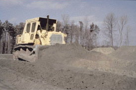
Spreading. Fly ash is usually spread and leveled with a dozer, grader, or other equipment in loose lifts of 150 to 300 mm (6 to 12 in) thick. The lift is then tracked with the dozer or other equipment for initial compaction.
Compaction equipment. Begin compaction as soon as the material has been spread and is at the proper moisture content. The most successful compaction results have been achieved with self-propelled, pneumatic-tired rollers and self-propelled or towed vibratory rollers. Vibratory rollers operated at the resonant frequency of the fly ash will compact the ash more effectively and in fewer passes than non-vibratory rollers. Table 6-1 lists the types of compaction equipment that have been tested for use with fly ash.
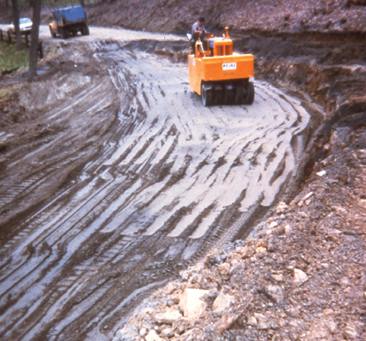
Figure 6-3: Spreading and compaction of fly ash structural fill.
Moisture control. Control of the required range of moisture is an important consideration in the compaction procedure. Fly ash can be conditioned with water at the plant silo to achieve the desired moisture content. Be sure to compare the alternatives of hauling fly ash moistened to the desired water content at the plant, or adding water at the site. Hauling moist fly ash to the site means higher transportation costs, while adding water on-site sacrifices productivity in field placement.
Weather restrictions. Fly ash can often be placed during inclement weather. In the winter months, frost usually penetrates only the upper layer of the compacted ash, which can be re-compacted upon thawing. During compaction, if the water freezes too fast, the operation should be suspended until the temperature rises. Construction can also proceed during wet weather even if the moisture content of the ash is too high. However, the equipment may bog down and it may be difficult to achieve proper compaction.
Insensitivity to moisture variations. Because water is added to low calcium fly ash during unloading from storage silos, fly ash can be obtained at any moisture content that is desired. Although the optimum moisture content is greater than that of silty soils, the compaction behavior of low calcium fly ash is relatively insensitive to variations in moisture content when placed dry of optimum. High calcium fly ash, however, will self-harden when water is added and becomes difficult to handle if not placed in a timely manner.