

Comprehensive Design Example for Prestressed Concrete (PSC) Girder Superstructure Bridge
Design Step 5 Design of Superstructure
Design Step 5.7 Shear Design (S5.8)
Shear design in the AASHTO-LRFD Specifications is based on the modified compression field theory. This method takes into account the effect of the axial force on the shear behavior of the section. The angle of the shear cracking, θ, and the shear constant, β, are both functions of the level of applied shear stress and the axial strain of the section. Figure S5.8.3.4.2-1 (reproduced below) illustrates the shear parameters.
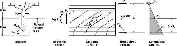
Figure S5.8.3.4.2-1 - Illustration of Shear Parameters for Section Containing at Least the Minimum Amount of Transverse Reinforcement, Vp = 0.
The transverse reinforcement (stirrups) along the beam is shown in Figure 5.7-1. Table 5.7-1 lists the variables required to be calculated at several sections along the beam for shear analysis.
A sample calculation for shear at several sections follows the table.
Notice that many equations contain the term Vp, the vertical component of the prestressing force. Since draped strands do not exist in the example beams, the value of Vp is taken as 0.
Table 5.7-1 Shear Analysis at Different Sections
| Dist.(1) (ft.) |
Aps (in2) |
As(3) (in2) |
CGS(4) (in.) |
de(5) (in.) |
c (Rectangular behavior)(6) (in.) |
c (T-section behavior) (7) (in.) |
de - β1c/2 (in.) |
0.9de (in.) |
dv (8) (in.) |
Vu (9) (kips) |
Vp (9,10) (kips) |
vu/f′c (11) | Mu (9,12) (kip-ft) |
Mu/dv (kips) |
|---|---|---|---|---|---|---|---|---|---|---|---|---|---|---|
| 7.00 | 4.90 | 5.375 | 74.13 | 4.06 | #N/A | 72.40 | 66.71 | 72.40 | 340.4 | 0.00 | 0.1088 | 2,241 | 371.4 | |
| 11.00 | 5.26 | 5.279 | 74.22 | 4.35 | #N/A | 72.37 | 66.80 | 72.37 | 315.1 | 0.00 | 0.1008 | 3,393 | 562.6 | |
| 16.50 | 5.81 | 5.158 | 74.34 | 4.80 | #N/A | 72.30 | 66.91 | 72.30 | 280.7 | 0.00 | 0.0899 | 4,755 | 789.2 | |
| 22.00 | 5.81 | 5.158 | 74.34 | 4.80 | #N/A | 72.14 | 66.91 | 72.14 | 246.7 | 0.00 | 0.0790 | 5,897 | 978.7 | |
| 27.50 | 6.73 | 5.000 | 74.50 | 5.55 | #N/A | 72.14 | 67.05 | 72.14 | 213.4 | 0.00 | 0.0685 | 6,821 | 1,134.6 | |
| 33.00 | 6.73 | 5.000 | 68.37 | 5.55 | #N/A | 72.14 | 67.05 | 72.14 | 180.6 | 0.00 | 0.0579 | 7,535 | 1,253.3 | |
| 38.50 | 6.73 | 5.000 | 68.37 | 5.55 | #N/A | 72.14 | 67.05 | 72.14 | 148.3 | 0.00 | 0.0476 | 8,063 | 1,341.2 | |
| 44.00 | 6.73 | 5.000 | 68.37 | 5.55 | #N/A | 72.14 | 67.05 | 72.14 | 116.7 | 0.00 | 0.0374 | 8,381 | 1,394.1 | |
| 49.50 | 6.73 | 5.000 | 68.37 | 5.55 | #N/A | 72.14 | 67.05 | 72.14 | 85.7 | 0.00 | 0.0275 | 8,494 | 1,412.9 | |
| 54.50 | 6.73 | 5.000 | 68.37 | 5.55 | #N/A | 72.14 | 67.05 | 72.14 | 118.4 | 0.00 | 0.0380 | 8,456 | 1,406.5 | |
| 55.00 | 6.73 | 5.000 | 68.37 | 5.55 | #N/A | 72.14 | 67.05 | 72.14 | 121.3 | 0.00 | 0.0389 | 8,440 | 1,403.9 | |
| 60.50 | 6.73 | 5.000 | 68.37 | 5.55 | #N/A | 72.14 | 67.05 | 72.14 | 153.5 | 0.00 | 0.0492 | 8,163 | 1,357.8 | |
| 66.00 | 6.73 | 5.000 | 68.37 | 5.55 | #N/A | 72.14 | 67.05 | 72.14 | 185.7 | 0.00 | 0.0596 | 7,690 | 1,279.1 | |
| 71.50 | 6.73 | 5.000 | 68.37 | 5.55 | #N/A | 72.14 | 67.05 | 72.14 | 217.9 | 0.00 | 0.0699 | 7,027 | 1,168.8 | |
| 77.00 | 6.73 | 5.000 | 68.37 | 5.55 | #N/A | 72.14 | 67.05 | 72.14 | 250.0 | 0.00 | 0.0802 | 6,180 | 1,028.0 | |
| 82.50 | 6.73 | 5.000 | 74.50 | 5.55 | #N/A | 72.14 | 67.05 | 72.14 | 282.0 | 0.00 | 0.0905 | 5,158 | 858.0 | |
| 88.00 | 5.81 | 5.158 | 74.34 | 4.80 | #N/A | 72.30 | 66.91 | 72.30 | 313.8 | 0.00 | 0.1005 | 3,966 | 658.2 | |
| 93.50 | 5.81(2) | 14.65 | 5.158 | 75.52 | 8.21 | #N/A | 72.44 | 67.97 | 72.44 | 345.4 | 0.00 | 0.1104 | -393 | 65.1 |
| 99.00 | 4.90(2) | 14.65 | 5.375 | 75.52 | 8.21 | #N/A | 72.44 | 67.97 | 72.44 | 376.8 | 0.00 | 0.1204 | -1,535 | 254.3 |
| 102.50 | 4.90(2) | 14.65 | 5.375 | 75.52 | 8.21 | #N/A | 72.44 | 69.97 | 72.44 | 396.6 | 0.00 | 0.1267 | -2,489 | 412.3 |
| Dist. (ft.) |
Apsfpo (2,13) (kips) |
θ (guess) (14) |
0.5(Vu - Vp) cot θ (kips) |
Net Force (kips) |
εx (15) (strain) |
Adjusted εx (16) (strain) |
θ (comp.) (17) |
β(17) | Vc (kips) |
Max. Stirrup Spcg. (in.) |
Vs (comp.) (kips) |
ΦVn (kips) |
Φ/bVn/Vu | Τ (18) (kips) |
|---|---|---|---|---|---|---|---|---|---|---|---|---|---|---|
| 7.00 | 926.1 | 22.60 | 408.9 | -145.8 | -0.000520 | -0.000026 | 22.60 | 3.05 | 136.7 | 16.0 | 260.9 | 307.8 | 1.051 | 967 |
| 11.00 | 994.1 | 22.80 | 374.8 | -56.7 | -0.000190 | -0.000010 | 22.80 | 3.07 | 137.6 | 18.0 | 229.5 | 317.3 | 1.049 | 1,123 |
| 16.50 | 1,098.1 | 22.33 | 341.7 | 32.8 | 0.000100 | 0.000100 | 24.75 | 2.99 | 133.9 | 21.0 | 179.2 | 305.6 | 1.004 | 1,272 |
| 22.00 | 1,098.1 | 28.66 | 225.7 | 106.3 | 0.000320 | 0.000320 | 28.66 | 2.74 | 122.7 | 20.0 | 158.7 | 311.1 | 1.027 | 1,335 |
| 27.50 | 1,272.0 | 26.03 | 218.4 | 81.0 | 0.000210 | 0.000210 | 26.03 | 3.02 | 134.9 | 24.0 | 147.7 | 329.0 | 1.192 | 1,469 |
| 33.00 | 1,272.0 | 28.55 | 165.9 | 147.2 | 0.000380 | 0.000380 | 29.53 | 2.68 | 119.7 | 24.0 | 127.4 | 321.2 | 1.232 | 1,495 |
| 38.50 | 1,272.0 | 31.30 | 122.0 | 191.2 | 0.000500 | 0.000500 | 31.30 | 2.54 | 113.5 | 24.0 | 118.7 | 317.7 | 1.409 | 1,515 |
| 44.00 | 1,272.0 | 31.30 | 96.0 | 218.1 | 0.000570 | 0.000570 | 32.10 | 2.49 | 111.2 | 24.0 | 115.0 | 316.8 | 1.744 | 1,509 |
| 49.50 | 1,272.0 | 31.30 | 70.5 | 211.4 | 0.000550 | 0.000550 | 31.30 | 2.54 | 113.5 | 24.0 | 118.7 | 318.1 | 2.438 | 1,472 |
| 54.50 | 1,272.0 | 32.10 | 94.4 | 228.9 | 0.000600 | 0.000600 | 32.10 | 2.49 | 111.2 | 24.0 | 115.0 | 315.8 | 1.720 | 1,525 |
| 55.00 | 1,272.0 | 32.10 | 96.7 | 228.6 | 0.000600 | 0.000600 | 32.10 | 2.49 | 111.2 | 24.0 | 115.0 | 315.8 | 1.678 | 1,527 |
| 60.50 | 1,272.0 | 31.30 | 126.2 | 212.0 | 0.000550 | 0.000550 | 31.30 | 2.54 | 113.5 | 24.0 | 118.7 | 316.2 | 1.362 | 1,541 |
| 66.00 | 1,272.0 | 29.53 | 163.9 | 171.0 | 0.000450 | 0.000450 | 30.50 | 2.59 | 115.7 | 24.0 | 122.5 | 318.8 | 1.155 | 1,526 |
| 71.50 | 1,272.0 | 27.28 | 208.5 | 105.3 | 0.000270 | 0.000270 | 27.85 | 2.85 | 127.3 | 24.0 | 138.1 | 238.9 | 1.097 | 1,500 |
| 77.00 | 1,272.0 | 23.83 | 283.0 | 39.0 | 0.000100 | 0.000100 | 24.45 | 3.16 | 141.2 | 24.0 | 158.7 | 269.9 | 1.080 | 1,465 |
| 82.50 | 1,272.0 | 22.33 | 343.2 | -70.8 | -0.000180 | -0.000012 | 22.33 | 3.29 | 147.0 | 21.0 | 175.6 | 290.3 | 1.030 | 1,407 |
| 88.00 | 1,098.1 | 22.80 | 373.2 | -66.7 | -0.000200 | -0.000012 | 22.80 | 3.07 | 137.4 | 19.0 | 217.3 | 319.2 | 1.017 | 1,229 |
| 93.50 | 1,098.1(2) | 30.20 | 296.7 | 361.8 | 0.000430 | 0.000430 | 30.20 | 2.56 | 114.8 | 11.0 | 271.6 | 347.8 | 1.007 | #N/A |
| 99.00 | 926.1(2) | 33.65 | 283.0 | 537.3 | 0.000630 | 0.000630 | 33.65 | 2.30 | 103.2 | 8.0 | 326.5 | 386.7 | 1.026 | #N/A |
| 102.50 | 926.1(2) | 35.17 | 281.4 | 693.7 | 0.000820 | 0.000820 | 35.81 | 2.19 | 98.2 | 7.0 | 344.3 | 398.3 | 1.004 | #N/A |
Notes:
- Distance measured from the centerline of the end support. Calculations for Span 1 are shown. From symmetry, Span 2 is a mirror image of Span 1.
- Prestressing steel is on the compression side of the section in the negative moment region of the girder (intermediate pier region). This prestressing steel is ignored where the area of steel in an equation is defined as the area of steel on the tension side of the section.
- Area of continuity reinforcement, i.e., the longitudinal reinforcement of the deck slab within the effective flange width of the girder in the girder negative moment region.
- Distance from the centroid of the tension steel reinforcement to the extreme tension fiber of the section. In the positive moment region, this is the distance from the centroid of prestressing strands to the bottom of the prestressed beam. In the negative moment region, this is the distance from the centroid of the longitudinal deck slab reinforcement to the top of the structural deck slab (ignore the thickness of the integral wearing surface).
- Effective depth of the section equals the distance from the centroid of the tension steel reinforcement to the extreme compression fiber of the section. In the positive moment region, this is the distance from the centroid of the prestressing strands to the top of the structural deck slab (ignore the thickness of the integral wearing surface). In the negative moment region, this is the distance from the centroid of the longitudinal deck slab reinforcement the bottom of the prestressed beam. The effective depth is calculated as the total depth of the section (which equals the depth of precast section, 72 in. + structural deck thickness, 7.5 in. = 79.5 in.) minus the quantity defined in note (4) above.
- Distance from the extreme compression fiber to the neutral axis calculated assuming rectangular behavior using Eq. S5.7.3.1.1-4. Prestressing steel, effective width of slab and slab compressive strength are considered in the positive moment region. The slab longitudinal reinforcement, width of the girder bottom (compression) flange and girder concrete strength are considered in the negative moment region.
- Distance from the extreme compression fiber to the neutral axis calculated assuming T-section behavior using Eq. S5.7.3.1.1-3. Only applicable if the rectangular section behavior proves untrue.
- Effective depth for shear calculated using S5.8.2.9.
- Maximum applied factored load effects obtained from the beam load analysis.
- Vertical component of prestressing which is 0.0 for straight strands
- The applied shear stress, vu, calculated as the applied factored shear force divided by product of multiplying the web width and the effective shear depth.
- Only the controlling case (positive moment or negative moment) is shown.
- In the positive moment region, the parameter fpo is taken equal to 0.7fpu of the prestressing steel as allowed by S5.8.3.4.2. This value is reduced within the transfer length of the strands to account for the lack of full development.
- Starting (assumed) value of shear crack inclination angle, θ, used to determine the parameter εx.
- Value of the parameter εx calculated using Eq. S5.8.3.4.2-1 which assumes that εx has a positive value.
- Value of the parameter εx recalculated using Eq. S5.8.3.4.2-3 when the value calculated using Eq. S5.8.3.4.2-1 is a negative value.
- Value of θ and β determined from Table S5.8.3.4.2-1 using the calculated value of εx and vu/f′c. These values are determined using a step function to interpolate between the values in Table S5.8.3.4.2-1.
- Force in longitudinal reinforcement including the effect of the applied shear (S5.8.3.5)
Design Step 5.7.1 - Critical section for shear near the end support
According to S5.8.3.2, where the reaction force in the direction of the applied shear introduces compression into the end region of a member, the location of the critical section for shear is taken as the larger of 0.5dvcot θ or dv from the internal face of the support (dv and θare measured at the critical section for shear). This requires the designer to estimate the location of the critical section first to be able to determine dv and θ, so a more accurate location of the critical section may be determined.
Based on a preliminary analysis, the critical section near the end support is estimated to be at a distance 7.0 ft. from the centerline of the end bearing. This distance is used for analysis and will be reconfirmed after determining dv and θ.
Design Step 5.7.2 - Shear analysis for a section in the positive moment region
Sample Calculations: Section 7.0 ft. from the centerline of the end bearing
Design Step 5.7.2.1 - Determine the effective depth for shear, dv
| dv | = effective shear depth taken as the distance, measured perpendicular to the neutral axis, between the resultants of the tensile and compressive forces due to flexure; it need not be taken to be less than the greater of 0.9de or 0.72h (S5.8.2.9) |
| h | = total depth of beam (in.) = depth of the precast beam + structural slab thickness = 72 + 7.5 = 79.5 in. (notice that the depth of the haunch was ignored in this calculation) |
| de | = distance from the extreme compression fiber to the center of the prestressing steel at the section (in.). From Figure 2-6,= 79.5 - 5.375 = 74.125 in. |
Assuming rectangular section behavior with no compression steel or mild tension reinforcement, the distance from the extreme compression fiber to the neutral axis, c, may be calculated as:
| c | = Apsfpu /[0.85f′cβ1b + kAps(fpu/dp)] (S5.7.3.1) |
| β1 | = 0.85 for 4 ksi slab concrete (S5.7.2.2) |
| b | = effective flange width = 111 in. (calculated in Section 2.2) |
Area of prestressing steel at the section = 32(0.153) = 4.896 in2
| c | = 4.896(270)/[0.85(4)(0.85)(111) + 0.28(4.896)(270/74.125)] = 4.06 in. < structural slab thickness = 7.5 in. The assumption of the section behaving as a rectangular section is correct. |
Depth of compression block, a = β1c = 0.85(4.06) = 3.45 in.
Distance between the resultants of the tensile and compressive forces due to flexure:| = de - a/2 = 74.125 - 3.45/2 = 72.4 in. (1) | |
| 0.9de | = 0.9(74.125) = 66.71 in. (2) |
| 0.72h | = 0.72(79.5) = 57.24 in. (3) |
| dv | = largest of (1), (2) and (3) = 72.4 in. |
Notice that 0.72h is always less than the other two values for all sections of this beam. This value is not shown in Table 5.7-1 for clarity.
Design Step 5.7.2.2 - Shear stress on concrete
From Table 5.3-4, the factored shear stress at this section, Vu = 340.4 kips
φ = resistance factor for shear is 0.9 (S5.5.4.2.1)
bv = width of web = 8 in. (see S5.8.2.9 for the manner in which bv is determined for sections with post-tensioning ducts and for circular sections)
From Article S5.8.2.9, the shear stress on the concrete is calculated as:
| vu | = (Vu - φVp)/(φbvdv)) = (340.4 - 0)/[0.9(8)(72.4)] = 0.653 ksi (S5.8.2.9-1) |
Ratio of applied factored shear stress to concrete compressive strength:
vu/f′c = 0.653/6.0 = 0.1088
Design Step 5.7.2.3 - Minimum required transverse reinforcement
Limits on maximum factored shear stresses for sections without transverse reinforcement are presented in S5.8.2.4. Traditionally, transverse reinforcement satisfying the minimum transverse reinforcement requirements of S5.8.2.5 is provided along the full length of the beam.
Minimum transverse reinforcement, Av:
| f′c | = compressive strength of the web concrete = 6.0 ksi |
| fy | = yield strength of the transverse reinforcement = 60 ksi |
Assume that #4 bars are used for the stirrups. Av = area of 2 legs of a #4 bar = 0.4 in2
Substitute 0.4 in2 to determine "s", the maximum allowable spacing of #4 bars (2-leg stirrups).
| 0.4 | ≥ 0.0316(2.449)(8/60)s |
| s | ≤ 38.77 in. |
Design Step 5.7.2.4 - Maximum spacing for transverse reinforcement
The maximum spacing of transverse reinforcement is determined in accordance with S5.8.2.7. Depending on the level of applied factored shear stress, vu, the maximum permitted spacing, smax, is determined as:
- If vu < 0.125f′c, then:
smax = 0.8dv < 24.0 in. (S5.8.2.7-1)
- If vu ≥ 0.125f′c, then:
smax = 0.4dv < 12.0 in. (S5.8.2.7-2)
For the section under consideration, vu = 0.1088f′c. Therefore, the maximum permitted spacing,
| smax | = 0.8dv = 0.8(72.4) = 57.9 in. > 24.0 in. NG, assume maximum permitted stirrup spacing = 24 in. |
Design Step 5.7.2.5 - Shear strength
The shear strength provided by the concrete, Vc, is calculated using the following equation:
The values of β and the shear cracking inclination angle, θ, are determined using the procedure outlined in S5.8.3.4.2. This iterative procedure begins with assuming a value of the parameter εx, or the crack inclination angle θ, then calculating a new εx value which is subsequently compared to the assumed value.
If the two values match, or the assumed value is slightly greater than the calculated value, no further iterations are required. Otherwise, a new cycle of analysis is conducted using the calculated value.
The calculations shown below are based on assuming a value of the crack inclination angle θ.
The flowcharts in Section 3 include two for shear analysis. The first flowchart is based on assuming the analyses are based on an assumed value of θ and the second flowchart is based on an assumed value of εx.
The parameter εx is a measure of the strain in the concrete on the tension side of the section. For sections containing at least the minimum transverse reinforcement calculated above, εx may be calculated using the following equations:
If the value of εx from Eqs. S5.8.3.4.2-1 or -2 is negative, the strain shall be taken as:
For this example, the value of both the applied factored axial load, Nu, and the vertical component of prestressing, Vp, are taken equal to 0.
For the section under consideration:
| Vu | = maximum applied factored shear = 340.4 kips |
| Mu | = maximum factored moment at the section = 2,241 k-ft |
Notice that the maximum live load moment and the maximum live load shear at any section are likely to result from two different locations of the load along the length of the bridge. Conducting the shear analysis using the maximum factored shear and the concurrent factored moment is permitted. However, most computer programs list the maximum values of the moment and the maximum value of the shear without listing the concurrent forces. Therefore, hand calculations and most design computer programs typically conduct shear analysis using the maximum moment value instead of the moment concurrent with the maximum shear. This results in a conservative answer.
According to S5.8.3.4.2, fpo is defined as follows:
| fpo = | a parameter taken as the modulus of elasticity of the prestressing tendons multiplied by the locked in difference in strain between the prestressing tendons and the surrounding concrete (ksi). For the usual levels of prestressing, a value of 0.7fpu will be appropriate for both pretensioned and posttensioned members. |
For pretensioned members, multiplying the modulus of elasticity of the prestressing tendons by the locked in difference in strain between the prestressing tendons and the surrounding concrete yields the stress in the strands when the concrete is poured around them, i.e., the stress in the strands immediately prior to transfer. For pretensioned members, SC5.8.3.4.2 allows fpo to be taken equal to the jacking stress. This value is typically larger than 0.7fpu. Therefore, using 0.7fpu is more conservative since it results in a larger value of εx.
For this example, fpo is taken as 0.7fpu
Notice that, as required by Article S5.8.3.4.2, within the transfer length, fpo shall be increased linearly from zero at the location where the bond between the strands and concrete commences to its full value at the end of the transfer length.
Assume that θ = 23.0 degrees (this value is based on an earlier cycle of calculations).
| Aps | = area of prestressed steel at the section = 32(0.153) = 4.896 in2 |
| dv | = 72.4 in. (6.03 ft.) |
As, Es, Aps and Eps are the area of mild tension reinforcement (0.0), modulus of elasticity of mild reinforcement (29,000 ksi), area of prestressing steel (4.896 in2) and modulus of elasticity of the prestressing strands (28,500 ksi), respectively.
Substitute these variables in Eq. S5.8.3.4.2-1 and recalculate εx.
εx = -0.00055 < 0.0 NG, therefore, use Eq. S5.8.3.4.2-3
The area of the concrete on the tension side of the beam is taken as the area of concrete on the tension side of the beam within half the total depth of the beam.
H/2 = one half of the total composite beam depth = 79.5/2 = 39.75 in.
From Figure S5.8.3.4.2-1 (reproduced above), the concrete area on the tension side, the lower 39.75 in. of the beam, equals 578 in2.
Modulus of elasticity of the beam concrete, ![]()
Substitute these variables in Eq. S5.8.3.4.2-3 and recalculate εx.
εx = -0.000027
At the section under consideration vu/f′c = 0.1088 (from Design Step 5.7.2.2 above)
Table S5.8.3.4.2-1 is reproduced below. This table is used to determine the value of θ and β at different sections.
Notice that:
Linear interpolation between the rows of the table is permitted to account for the value of vu/f′c at the section
Linear interpolation between the columns of the table is allowed to account for the calculated value of εx
In lieu of interpolating, using values of θ and β from a cell that correspond to the values of vu/f′c and εx greater than the calculated values is permitted. This approach is preferred for hand calculations and will result in a conservative answer.
Using Table S5.8.3.4.2-1 for the above values of εx and vu/f′c:
Use the row that corresponds to vu/f′c ≤ 0.125 (this value is next greatest to the calculated value of vu/f′c)
Use the column corresponding to εx ≤ 0.0 (the value in Table S5.8.3.4.2-1 that is next larger to the assumed value of εx)
| θ | = 23.7 degrees |
| β | = 2.87 |
Check the assumed value of θ:
For the purpose of calculating εx, the value of θ was assumed to be 23.0 degrees. This value is close to the value obtained above. Therefore, the assumed value of θ was appropriate and there is no need for another cycle of calculations.
Notice that the assumed and calculated values of θ do not need to have the same exact value. A small difference will not drastically affect the outcome of the analysis and, therefore, does not warrant conducting another cycle of calculations. The assumed value may be accepted if it is larger than the calculated value.
Notice that the values in Table 5.7-1 are slightly different (22.60 and 3.05). This is true since the spreadsheet used to determine the table values uses a step function instead of linear interpolation.
Calculate the shear resistance provided by the concrete, Vc.
| Vc | = 0.0316(2.87)(2.449)(8)(72.4) = 128.6 k |
Calculate the shear resistance provided by the transverse reinforcement (stirrups), Vs.
Vs = [Avfydv(cot θ + cot a)sin α]/s (S5.8.3.3-4)
Assuming the stirrups are placed perpendicular to the beam longitudinal axis at 16 in. spacing and are comprised of #4 bars, each having two legs:
| Av | = area of shear reinforcement within a distance "s" (in2) = 2(area of #4 bar) = 2(0.2) = 0.4 in2 |
| s | = 16 in. |
| α | = angle between the stirrups and the longitudinal axis of the beam = 90 degrees |
| Vs | = [0.4(60)(72.4)(cot 23.0)]/16 = 255.8 k |
The nominal shear resistance, Vn, is determined as the lesser of:
Vn = Vc + Vs + Vp (S5.8.3.3-1)
Vn = 0.25f′cbvdv + Vp (S5.8.3.3-2)
Notice that the purpose of the limit imposed by Eq. S5.8.3.3-2 is intended to eliminate excessive shear cracking.
Vp = 0.0 for straight strands
Vn = lesser of:
Vc + Vs + Vp = 128.6 + 255.8 + 0.0 = 384.4 k
and
0.25f′cbvdv + Vp = 0.25(6)(8)(72.4) + 0.0 = 868.8 k
Therefore, Vn = 384.4 k
The resistance factor, φ, for shear in normal weight concrete is 0.9 (S5.5.4.2.1)
Shear factored resistance, Vr:
| Vr | = φVn (S5.8.2.1-2) = 0.9(384.4) = 346.0 k > maximum applied factored shear, Vu = 340.4 k OK |
Table S5.8.3.4.2-1 - Values of θand β for Sections with Transverse Reinforcement (Reproduced from the AASHTO-LRFD Specifications)
| v/f'c | εx x 1,000 | ||||||||||
|---|---|---|---|---|---|---|---|---|---|---|---|
| ≤ -0.20 | ≤ -0.10 | ≤ -0.05 | ≤ 0 | ≤ 0.125 | ≤ 0.25 | ≤ 0.50 | ≤ 0.75 | ≤ 1.00 | ≤ 1.50 | ≤ 2.00 | |
| ≤ 0.075 | 22.3 | 20.4 | 21.0 | 21.8 | 24.3 | 26.6 | 30.5 | 33.7 | 36.4 | 40.8 | 43.9 |
| 6.32 | 4.75 | 4.10 | 3.75 | 3.24 | 2.94 | 2.59 | 2.38 | 2.23 | 1.95 | 1.67 | |
| ≤ 0.100 | 18.1 | 20.4 | 21.4 | 22.5 | 24.9 | 27.1 | 30.8 | 34.0 | 36.7 | 40.8 | 43.1 |
| 3.79 | 3.38 | 3.24 | 3.14 | 2.91 | 2.75 | 2.50 | 2.32 | 2.18 | 1.93 | 1.69 | |
| ≤ 0.125 | 19.9 | 21.9 | 22.8 | 23.7 | 25.9 | 27.9 | 31.4 | 34.4 | 37.0 | 41.0 | 43.2 |
| 3.18 | 2.99 | 2.94 | 2.87 | 2.74 | 2.62 | 2.42 | 2.26 | 2.13 | 1.90 | 1.67 | |
| ≤ 0.150 | 21.6 | 23.3 | 24.2 | 25.0 | 26.9 | 28.8 | 32.1 | 34.9 | 37.3 | 40.5 | 42.8 |
| 2.88 | 2.79 | 2.78 | 2.72 | 2.60 | 2.52 | 2.36 | 2.21 | 2.08 | 1.82 | 1.61 | |
| ≤ 0.175 | 23.2 | 24.7 | 25.5 | 26.2 | 28.0 | 29.7 | 32.7 | 35.2 | 36.8 | 39.7 | 42.2 |
| 2.73 | 2.66 | 2.65 | 2.60 | 2.52 | 2.44 | 2.28 | 2.14 | 1.96 | 1.71 | 1.54 | |
| ≤ 0.200 | 24.7 | 26.1 | 26.7 | 27.4 | 29.0 | 30.6 | 32.8 | 34.5 | 36.1 | 39.2 | 41.7 |
| 2.63 | 2.59 | 2.52 | 2.51 | 2.43 | 2.37 | 2.14 | 1.94 | 1.79 | 1.61 | 1.47 | |
| ≤ 0.225 | 26.1 | 27.3 | 27.9 | 28.5 | 30.0 | 30.8 | 32.3 | 34.0 | 35.7 | 38.8 | 41.4 |
| 2.53 | 2.45 | 2.42 | 2.40 | 2.34 | 2.14 | 1.86 | 1.73 | 1.64 | 1.51 | 1.39 | |
| ≤ 0.250 | 27.5 | 28.6 | 29.1 | 29.7 | 30.6 | 31.3 | 32.8 | 34.3 | 35.8 | 38.6 | 41.2 |
| 2.39 | 2.39 | 2.33 | 2.33 | 2.12 | 1.93 | 1.70 | 1.58 | 1.50 | 1.38 | 1.29 | |
Check the location of the critical section for shear near the end support
According to S5.8.3.2, where the reaction force in the direction of the applied shear introduces compression into the end region of a member, the location of the critical section for shear shall be taken as the larger of 0.5dvcot θ or dv from the internal face of the support. For existing bridges, the width of the bearing is known and the distance is measured from the internal face of the bearings. For new bridges, the width of the bearing is typically not known at this point of the design and one of the following two approaches may be used:
Estimate the width of the bearing based on past experience.
Measure the distance from the CL of bearing. This approach is slightly more conservative.
The second approach is used for this example.
For calculation purposes, the critical section for shear was assumed 7.0 ft. from the centerline of the bearing (see Design Step 5.7.1). The distance from the centerline of the support and the critical section for shear may be taken as the larger of 0.5dvcot θ and dv.
0.5dvcot θ = 0.5(72.4)(cot 23.7) = 82.5 in. (6.875 ft.)
dv = 72.4 in. (6.03 ft.)
The larger of 0.5dvcot θ and dv is 82.5 in. (6.875 ft.)
The distance assumed in the analysis was 7.0 ft., i.e., approximately 0.125 ft. (0.1% of the span length) further from the support than the calculated distance. Due to the relatively small distance between the assumed critical section location and the calculated section location, repeating the analysis based on the applied forces at the calculated location of the critical section is not warranted. In cases where the distance between the assumed location and the calculated location is large relative to the span length, another cycle of the analysis may be conducted taking into account the applied forces at the calculated location of the critical section.
Design Step 5.7.3 - Shear analysis for sections in the negative moment region
The critical section for shear near the intermediate pier may be determined using the same procedure as shown in Design Steps 5.7.1 and 5.7.2 for a section near the end support. Calculations for a section in the negative moment region are illustrated below for the section at 99 ft. from the centerline of the end bearing. This section is not the critical section for shear and is used only for illustrating the design process.
Sample Calculations: Section 99 ft. from the centerline of end bearings
Design Step 5.7.3.1 - Difference in shear analysis in the positive and negative moment regions
For the pier (negative moment) regions of precast simple span beams made continuous for live load, the prestressing steel near the piers is often in the compression side of the beam. The term Aps in the equations for εx is defined as the area of prestressing steel on the tension side of the member. Since the prestressing steel is on the compression side of the member, this steel is ignored in the analysis. This results in an increase in εx and, therefore, a decrease in the shear resistance of the section. This approach gives conservative results and is appropriate for hand calculations.
A less conservative approach is to calculate εx as the average longitudinal strain in the web. This requires the calculation of the strain at the top and bottom of the member at the section under consideration at the strength limit state. This approach is more appropriate for computer programs.
The difference between the two approaches is insignificant in terms of the cost of the beam. The first approach requires more shear reinforcement near the ends of the beam. The spacing of the stirrups in the middle portion of the beam is often controlled by the maximum spacing requirements and, hence, the same stirrup spacing is often required by both approaches.
It is beneficial to use the second approach in the following situations:
- Heavily loaded girders where the first approach results in congested shear reinforcement
- Analysis of existing structures where the first approach indicates a deficiency in shear resistance.
In calculating the distance from the neutral axis to the extreme compression fiber "c", the following factors need to be considered:
- The compression side is at the bottom of the beam. The concrete strength used to determine "c" is that of the precast girder
- The width of the bottom flange of the beam is substituted for "b", the width of the member
- The area of the slab longitudinal reinforcement over the intermediate pier represents the reinforcement on the tension side of the member. The area and yield strength of this reinforcement should be determined in advance.
The first approach is used in this example.
Design Step 5.7.3.2 - Determine the effective depth for shear, dv
h = 72 + 7.5 = 79.5 in. (notice that the depth of the haunch was ignored in this calculation)
The center of gravity of the deck slab longitudinal reinforcement from the top of the structural thickness of the deck = 3.98 in. (see Design Step 5.6.5.1)
de = 79.5 - 3.98 = 75.52 in.
The area of longitudinal slab reinforcement within the effective flange width of the beam is 14.65 in2 (see Design Step 5.6.5.1)
Yield strength of the slab reinforcement = 60 ksi
Assuming rectangular section behavior with no compression or prestressing steel, the distance from the extreme compression fiber to the neutral axis, c, may be calculated as:
c = Asfy /(0.85f′cβ1b) (S5.7.3.1.1-4)where:
β1 = 0.75 for 6 ksi beam concrete (S5.7.2.2) b = precast beam bottom (compression) flange width (in.)
= 28 in.f′c = 6 ksi
| c | = 14.65(60)/[0.85(6)(0.75)(28)] = 8.21 in. ≈ thickness of the beam bottom flange (8 in.) |
Therefore, the assumption of the section behaving as a rectangular section is considered correct.
Notice that if the value of "c" is significantly larger than the beam bottom flange thickness, a rectangular behavior may be used after adjusting the beam bottom flange width to account for the actual beam area in compression. However, if "c" is not significantly larger than the beam bottom flange thickness, the effect on the results will be minor and the analysis may be continued without adjusting the beam bottom flange width. This reasoning is used in this example.
Depth of compression block, a = β1c = 0.75(8.21) = 6.16 in.
Distance between the resultants of the tensile and compressive forces due to flexure:| = de - a/2 = 75.52 - 6.16/2 = 72.44 in. (1) | ||
| 0.9de | = 0.9(75.52) = 67.97 in. (2) |
|
| 0.72h | = 0.72(79.5) = 57.24 in. (3) |
|
| dv | = largest of (1), (2) and (3) = 72.44 in. |
Notice that 0.72h is always less than the other two values for all sections of this beam. This value is not shown in Table 5.7-1 for clarity.
Design Step 5.7.3.3 - Shear stress on concrete
From Table 5.3-4, the factored shear stress at this section, Vu = 376.8 kips
φ = 0.9 (shear) (S5.5.4.2.1)
bv = width of web = 8 in.
From Article S5.8.2.9, the shear stress on the concrete is:
vu = (Vu - φVp)/(φbvdv)
vu = (376.8 - 0)/[0.9(8)(72.44)] = 0.722 ksi
Ratio of the applied factored shear stress to the concrete compressive strength:
vu/f′c = 0.722/6.0 = 0.1203
Design Step 5.7.3.4 - Minimum required transverse reinforcement
Maximum allowable spacing for #4 stirrups with two legs per stirrup was calculated in Design Step 5.7.2.2.
s ≤ 38.77 in.
Design Step 5.7.3.5 - Maximum spacing for transverse reinforcement
The maximum spacing of transverse reinforcement is determined in accordance with S5.8.2.7. Depending on the level of applied factored shear stress, vu, the maximum permitted spacing, smax, is determined as:
If vu < 0.125f′c, then:
smax = 0.8dv < 24.0 in. (S5.8.2.7-1)
If vu ≥ 0.125f′c, then:
smax = 0.4dv < 12.0 in. (S5.8.2.7-2)
For the section under consideration, vu = 0.1203f′c.
Therefore, the maximum permitted spacing,
| smax | = 0.8dv = 0.8(72.44) = 57.95 in. > 24.0 in. NG |
Assume maximum permitted stirrup spacing = 24 in.
Design Step 5.7.3.6 - Shear resistance
For sections in the negative moment region of the beam, calculate εx, using Eq. S5.8.3.4.2-1 and assume there is no prestressing steel.
For this example, the value of both the applied factored axial load, Nu, and the vertical component of prestressing, Vp, are taken equal to 0.
| Vu | = maximum applied factored shear from Table 5.3-4 = 376.8 kips |
| Mu | = maximum applied factored moment from Table 5.3-2 = -1,535 k-ft |
Notice that the term Mu/dv represents the force in the tension reinforcement due to the applied factored moment. Therefore, Mu/dv is taken as a positive value regardless of the sign of the moment.
Assume that θ = 35 degrees
| fpo | = 0.0 ksi at this location (prestressing force ignored) |
| As | = area of longitudinal reinforcement in the deck at this section = 14.65 in2 |
Notice that the area of deck longitudinal reinforcement used in this calculation is the area of the bars that extend at least one development length beyond the section under consideration. If the section lies within the development length of some bars, these bars may be conservatively ignored or the force in these bars be prorated based on the ratio between the full and available development length. Consideration should also be given to adjusting the location of the center of gravity of the reinforcement to account for the smaller force in the bars that are not fully developed.
| dv | = 72.44 in. (6.04 ft.) |
| Es | = 29,000 ksi |
| Eps | = 28,500 ksi |
| Aps | = area of prestressing steel on the tension side of the member = 0.0 in2 |
Substitute these variables in Eq. S5.8.3.4.2-1 to determine εx:
| εx | = [1,535(12)/72.44 + 0.5(376.8 - 0)cot 35 - 0]/[2(29,000)(14.65) + 0] = 0.00062 |
At the section under consideration vu/f′c = 0.1203 (from Design Step 5.7.3.3)
Determine the values of θ and β using" />Table S5.8.3.4.2-1 (reproduced above)
If no interpolation between the values in Table S5.8.3.4.2-1 is desired:
Use the row and column that have the closest headings, but still larger than the calculated values, i.e.:
Use the row that corresponds to vu/f′c ≤ 0.125
Use the column corresponding to εx ≤ 0.00075
θ = 34.4 degrees
β = 2.26
If interpolation between the values in Table S5.8.3.4.2-1 is desired:
Interpolate between the values in the row with heading values closest to the calculated vu/f′c = 0.1203, i.e., interpolate between the rows with headings of vu /f′c ≤ 0.1 and ≤ 0.125. Then, interpolate between the values in the columns with heading values closest to the calculated εx = 0.00062, i.e., interpolate between the columns with headings of εx ≤ 0.0005 and ≤ 0.00075. The table below shows the relevant portion of Table S5.8.3.4.2-1 with the original and interpolated values. The shaded cells indicate interpolated values.
Excerpt from Table S5.8.3.4.2-1
v/f'c εx x 1,000 ≤ 0.50 0.62 ≤ 0.75 ≤ 0.100 30.8 34.0 2.50 2.32 0.1203 31.29 32.74 34.32 2.44 2.36 2.27 ≤ 0.125 31.4 34.4 2.42 2.26
From the sub-table:
θ = 32.74 degrees
β = 2.36
Notice that the interpolated values are not significantly different from the ones calculated without interpolation. The analyses below are based on the interpolated values to provide the user with a reference for this process.
Check the assumed value of θ
For the purpose of calculating εx, the value of θ was assumed to be 35 degrees. This value is close to the calculated value (32.74 degrees) and conducting another cycle of the analysis will not result in a significant difference. However, for the purpose of providing a complete reference, another cycle of calculations is provided below.
Assume that θ is the calculated value of 32.74 degrees
Substituting for the variables in Eq. S5.8.3.4.2-1for εx:
εx = 0.00064
Determine the values of θand β by interpolating the values in Table S5.8.3.4.2-1
θ = 32.98 degrees (almost equal to the assumed value, OK)
β = 2.34
Notice that the values in Table 5.7-1 are slightly different (33.65 and 2.30). This is true since the spreadsheet used to determine the table values uses a step function instead of linear interpolation.
Calculate the shear resistance provided by concrete, Vc:
Vc = 0.0316(2.34)(2.449)(8)(72.44) = 104.94 k
Calculate the shear resistance provided by the transverse reinforcement (stirrups), Vs:
Vs = [Avfydv(cot θ + cot α)sin α]/s (S5.8.3.3-4)
Assuming the stirrups are placed perpendicular to the beam longitudinal axis at 7 in. spacing and are comprised of #4 bars, each having two legs:
| Av | = 2(area of #4 bar) = 2(0.2) = 0.4 in2 |
| s | = 7 in. |
| α | = 90 degrees |
| Vs | = 0.4(60)(72.44)(cot 32.98)/7 = 382.74 k |
The nominal shear resistance, Vn, is determined as the lesser of:
Vn = Vc + Vs + Vp (S5.8.3.3-1)
Vn = 0.25f′cbvdv + Vp (S5.8.3.3-2)
Notice that the purpose of the limit imposed by Eq. S5.8.3.3-2 is intended to eliminate excessive shear cracking.
Vp = 0.0 for straight strands
Vn is taken as the lesser of:
Vc + Vs + Vp = 104.94 + 382.74 + 0.0 = 487.68 k
and
0.25f′cbvdv + Vp = 0.25(6)(8)(72.44) + 0.0 = 869.3 k
Therefore, Vn = 487.68 k
The resistance factor, φ, for shear in normal weight concrete = 0.90 (S5.5.4.2.1)
Factored shear resistance:
| Vr | = φ Vn = 0.9(487.68) = 438.91 k > max. applied factored shear, Vu = 376.8 k OK |
Design Step 5.7.4 - Factored bursting resistance (S5.10.10.1)
The bursting resistance of the pretensioned anchorage zones is calculated according to S5.10.10.1 at the service limit state.
Pr = fsAs (S5.10.10.1-1)
where:
fs = stress in the steel not exceeding 20 ksi As = total area of vertical reinforcement located within the distance h/4 from the end of the beam (in2) h = overall depth of the precast member (in.)
The resistance shall not be less than 4% of the prestressing force at transfer.
From Design Step 5.4.4:
| Prestressing force at transfer at end of beam | = 32(0.153)(188.8) = 924.4 kips |
Determine the required area of steel to meet the minimum resistance using fs = 20 ksi (max).
Therefore,
| 0.04(924.4) | = 20(As) |
| As | = 1.85 in2 |
Since one stirrup is 0.4 in2 (includes 2 legs), determine the number of stirrups required.
1.85/0.4 = 4.63 Say 5 stirrups required
These stirrups must fit within h/4 distance from the end of the beam.
| h/4 | = 72/4 = 18 in. |
Use 5 stirrups at 3 in. spacing as shown in Figure 5.7-1.
Design Step 5.7.5 - Confinement reinforcement (S5.10.10.2)
For the distance of 1.5d [1.5(72/12) = 9 ft.] from the end of the beam, reinforcement shall be placed to confine the prestressing steel in the bottom flange. The reinforcement is required to be not less than No. 3 deforming bars, with spacing not exceeding 6.0 in. and shaped to enclose the strands. The stirrups required to resist the applied shear and to satisfy the maximum stirrup requirements are listed in Table 5.7-1 for different sections. The maximum required spacings shown in Table 5.7-1 in the end zones of the beam is greater than 6 in. For a beam where all strands are located in the bottom flange, two different approaches may be utilized to provide the required confinement reinforcement:
Reduce the stirrup spacing in the end zone (1.5d) to not greater than 6 in.
Place the main vertical bars of the stirrups at the spacing required by vertical shear analysis. Detail the vertical bars in the bottom of the beam to enclose the prestressing and place these bars at a spacing not greater than 6 in. within the end zones. The stirrups and the confinement bars in this approach will not be at the same spacing and pouring of the concrete may be difficult.
For a beam where some strands are located in the web approach (1) should be used.
For this example, approach (1) was used. This is the basis for the stirrup distribution shown in Figure 5.7-1.
Figure 5.7-1- Beam Transverse Reinforcement
Figure 5.7-2 - Section A-A from Figure 5.7-1, Beam Cross Section Near the Girder Ends
Design Step 5.7.6 - Force in the longitudinal reinforcement including the effect of the applied shear (S5.8.3.5)
In addition to the applied moment, Mu, the following force effects contribute to the force in the longitudinal reinforcement:
- Applied shear forces, Vu
- Vertical component of the prestressing force
- Applied axial force, Nu
- The shear force resisted by the transverse reinforcement, Vs
To account for the effect of these force effects on the force in the longitudinal reinforcement, S5.8.3.5 requires that the longitudinal reinforcement be proportioned so that at each section, the tensile capacity of the reinforcement on the flexural tension side of the member, taking into account any lack of full development of that reinforcement, is greater than or equal to the force T calculated as:
where:
Vs = shear resistance provided by the transverse reinforcement at the section under investigation as given by Eq. S5.8.3.3-4, except Vs needs to be greater than Vu/φ (kips) θ = angle of inclination of diagonal compressive stresses used in determining the nominal shear resistance of the section under investigation as determined by S5.8.3.4 (deg) φ = resistance factors taken from S5.5.4.2 as appropriate for moment, shear and axial resistance
This check is required for sections located no less than a distance equal to 0.5dvcot θ from the support. The values for the critical section for shear near the end support are substituted for dv and θ.
0.5(72.44) cot 22.6 = 87.01 in. ≈ 7.0 ft.
The check for tension in the longitudinal reinforcement may be performed for sections no closer than 7.0 ft. from the support.
Sample calculation: Section at 7.0 ft. from the centerline of bearing at the end support
Using information from Table 5.7-1
Force in the longitudinal reinforcement at nominal flexural resistance, T
| T | = 2,241(12)/[72.40(1.0)] + 0 + [(340.4/0.9) - 0.5(260.9) - 0]cot 22.6 = 966.7 kips |
From Table 5.5-1, the maximum strand resistance at this section at the nominal moment resistance is 1,128.1 kips > T = 966.7 kips OK
Design Step 5.7.7
Horizontal shear between the beam and slab
Table 5.7-2 - Interface Shear Calculations
| Dist. (ft.) |
de (in.) |
Vu (kips) |
Max. Stirrup Spcg (in.) |
Interface reinf., Avf (in2/in.) |
Horiz. Shear, Vh (k/in.) |
Nominal resistance (k/in.) |
Factored resistance (k/in.) |
resist./ applied load 1.0 OK |
|---|---|---|---|---|---|---|---|---|
| 7.00 | 74.13 | 340.40 | 16.0 | 0.050 | 4.59 | 7.20 | 6.48 | 1.41 |
| 11.00 | 74.22 | 315.10 | 18.0 | 0.044 | 4.25 | 6.84 | 6.16 | 1.45 |
| 16.50 | 74.34 | 280.66 | 21.0 | 0.038 | 3.78 | 6.48 | 5.83 | 1.54 |
| 22.00 | 74.34 | 246.74 | 20.0 | 0.040 | 3.32 | 6.60 | 5.94 | 1.79 |
| 27.50 | 74.50 | 213.36 | 24.0 | 0.033 | 2.86 | 6.18 | 5.56 | 1.94 |
| 33.00 | 74.50 | 180.55 | 24.0 | 0.033 | 2.42 | 6.18 | 5.56 | 2.30 |
| 38.50 | 74.50 | 148.33 | 24.0 | 0.033 | 1.99 | 6.18 | 5.56 | 2.79 |
| 44.00 | 74.50 | 116.71 | 24.0 | 0.033 | 1.57 | 6.18 | 5.56 | 3.55 |
| 49.50 | 74.50 | 85.74 | 24.0 | 0.033 | 1.15 | 6.18 | 5.56 | 4.83 |
| 54.50 | 74.50 | 118.40 | 24.0 | 0.033 | 1.59 | 6.18 | 5.56 | 3.50 |
| 55.00 | 74.50 | 121.32 | 24.0 | 0.033 | 1.63 | 6.18 | 5.56 | 3.42 |
| 60.50 | 74.50 | 153.49 | 24.0 | 0.033 | 2.06 | 6.18 | 5.56 | 2.70 |
| 66.00 | 74.50 | 185.68 | 24.0 | 0.033 | 2.49 | 6.18 | 5.56 | 2.23 |
| 71.50 | 74.50 | 217.85 | 24.0 | 0.033 | 2.92 | 6.18 | 5.56 | 1.90 |
| 77.00 | 74.50 | 249.96 | 24.0 | 0.033 | 3.36 | 6.18 | 5.56 | 1.66 |
| 82.50 | 74.50 | 281.95 | 21.0 | 0.033 | 3.78 | 6.18 | 5.56 | 1.47 |
| 88.00 | 74.34 | 313.79 | 19.0 | 0.042 | 4.22 | 6.72 | 6.05 | 1.43 |
| 93.50 | 75.52 | 345.42 | 11.0 | 0.073 | 4.57 | 8.58 | 7.72 | 1.69 |
| 99.00 | 75.52 | 376.79 | 8.0 | 0.100 | 4.99 | 10.20 | 9.18 | 1.84 |
| 102.50 | 75.52 | 396.58 | 7.0 | 0.114 | 5.25 | 11.04 | 9.94 | 1.89 |
Sample calculations at 11 ft. from the centerline of bearing on the abutment (11 ft. - 9 in. from girder end)
Horizontal shear forces develop along the interface between the concrete girders and the deck. As an alternative to the classical elastic strength of materials approach, the value of these forces per unit length of the girders at the strength limit state can be taken as:
Vh = Vu/de (SC5.8.4.1-1)
where:
Vh = horizontal shear per unit length of the girder (kips) Vu = the factored vertical shear (kips) = 315.1 k (From Table 5.7-2) de = distance between the centroid of the steel in the tension side of the beam to the center of the compression blocks in the deck (in.) = 74.22 in. (see Table 5.7-2)
| Vh | = 315.1/74.22 = 4.25 k/in. |
Stirrup spacing at this location = 18 in.
Assume that the stirrups extend into the deck. In addition, assume that there is another #4 bar with two legs extending into the deck as shown in Figure 5.7-2.
Area of reinforcement passing through the interface between the deck and the girder, Avf
| Avf | = 4 #4 bars = 4(0.2) = 0.8 in2 |
Avf per unit length of beam = 0.8/18 = 0.044 in2/in. of beam length.
Check if the minimum interface shear reinforcement may be waived (S5.8.4.1)
| Shear stress on the interface | = Vh/area of the interface = 4.25/42 = 0.101 ksi > 0.1 ksi, minimum reinforcement requirement may not be waived |
Notice that the difference is only 1%. For actual design, this difference would be within acceptable tolerances, therefore, the minimum reinforcement requirement could be waived. For this example, in order to provide a complete reference, the minimum reinforcement requirement will not be waived.
Check the minimum interface shear reinforcement
| Avf | ≥ 0.05bv/fy = 0.05(42)/60 (S5.8.4.1-4) 0.035 in2/in. of beam length < As provided OK |
Shear friction resistance
The interface shear resistance of the interface has two components. The first component is due to the adhesion between the two surfaces. The second component is due to the friction. In calculating friction, the force acting on the interface is taken equal to the compression force on the interface plus the yield strength of the reinforcement passing through the interface. The nominal shear resistance of the interface plane, Vn, is calculated using S5.8.4.1.
Vn = cAcv + μ(Avffy + Pc) (S5.8.4.1-1)
where:
Vn = nominal shear friction resistance (kips) Acv = area of concrete engaged in shear transfer (in2) Avf = area of shear reinforcement crossing the shear plane (in2) fy = yield strength of reinforcement (ksi) c = cohesion factor specified in S5.8.4.2 (ksi) μ = friction factor specified in S5.8.4.2 Pc = permanent net compressive force normal to the shear plane (kips)
Calculate the nominal shear resistance per unit length of beam.
Assuming the top surface of the beam was clean and intentionally roughened,
c = 0.1 ksi and μ = 1.0λ (S5.8.4.2)
Ignore compression on the interface from loads on the deck: Pc = 0.0
Acv = 42 in2/in. of beam length
Avf = 0.044 in2/in. of beam length
fy = 60 ksi
Therefore,
| Vn | = 0.1(42) + 1.0[0.044(60) + 0.0] = 6.84 k/in. of beam length |
According to S5.8.4.1, the nominal shear resistance, Vn, used in the design must also satisfy:
Vn ≤ 0.2f′cAcv (S5.8.4.1-2)
OR
Vn ≤ 0.8Acv (S5.8.4.1-3)where:
f′c = the strength of the weaker concrete (ksi)
= 4.0 ksi for slab concrete
Vn ≤ 0.2 f′cAcv = 0.2(4.0)(42) = 33.6 k/in. of beam length
OR
Vn ≤ 0.8Acv = 0.8(42) = 33.6 k/in. of beam length
Therefore, Vn used for design = 7.02 k/in. of beam length.
| Vr | = φVn = 0.9(6.84) = 6.16 k/in. of beam length > applied force, Vh = 4.25 k/in. OK |