LRFD Steel Girder SuperStructure Design Example
Steel Girder Design Example Design Step 3
Table of Contents
Design Step 3.1 - Obtain Design Criteria
Design Step 3.2 - Select Trial Girder Section
Design Step 3.3 - Compute Section Properties
Design Step 3.4 - Compute Dead Load Effects
Design Step 3.5 - Compute Live Load Effects
Design Step 3.6 - Combine Load Effects
Positive Moment Region:Design Step 3.7 - Check Section Proportion LimitsNegative Moment Region:
Design Step 3.8 - Compute Plastic Moment Capacity
Design Step 3.9 - Determine if Section is Compact or Noncompact
Design Step 3.10 - Design for Flexure - Strength Limit State
Design Step 3.11 - Design for Shear
Design Step 3.12 - Design Transverse Intermediate Stiffeners
Design Step 3.14 - Design for Flexure - Fatigue and Fracture
Design Step 3.15 - Design for Flexure - Service Limit State
Design Step 3.16 - Design for Flexure - Constructibility Check
Design Step 3.17 - Check Wind Effects on Girder Flanges
Design Step 3.7 - Check Section Proportion Limits
Design Step 3.8 - Compute Plastic Moment Capacity
Design Step 3.9 - Determine if Section is Compact or Noncompact
Design Step 3.10 - Design for Flexure - Strength Limit State
Design Step 3.11 - Design for Shear
Design Step 3.12 - Design Transverse Intermediate Stiffeners
Design Step 3.14 - Design for Flexure - Fatigue and Fracture
Design Step 3.15 - Design for Flexure - Service Limit State
Design Step 3.16 - Design for Flexure - Constructibility Check
Design Step 3.17 - Check Wind Effects on Girder Flanges
Design Step 3.18 - Draw Schematic of Final Steel Girder Design
Design Step 3.1 - Obtain Design Criteria
The first design step for a steel girder is to choose the correct design criteria.
The steel girder design criteria are obtained from Figures 3-1 through 3-3 (shown below), from the concrete deck design example, and from the referenced articles and tables in the AASHTO LRFD Bridge Design Specifications (through 2002 interims). For this steel girder design example, a plate girder will be designed for an HL-93 live load. The girder is assumed to be composite throughout.
Refer to Design Step 1 for introductory information about this design example. Additional information is presented about the design assumptions, methodology, and criteria for the entire bridge, including the steel girder.
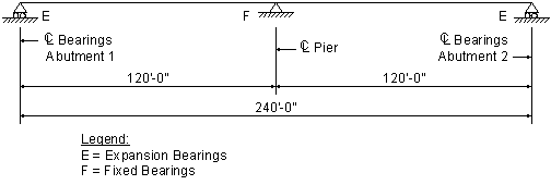
Figure 3-1 Span Configuration
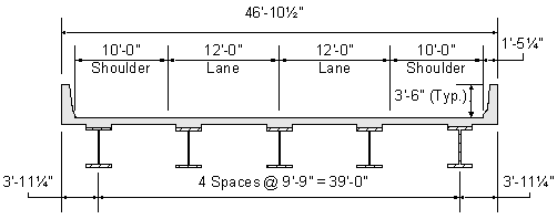
Figure 3-2 Superstructure Cross Section
 |
Girder Spacing Where depth or deflection limitations do not control the design, it is generally more cost-effective to use a wider girder spacing. For this design example, the girder spacing shown in Figure 3-2 was developed as a reasonable value for all limit states. Four girders are generally considered to be the minimum, and five girders are desirable to facilitate future redecking. Further optimization of the superstructure could be achieved by revising the girder spacing. |
 |
Overhang Width The overhang width is generally determined such that the moments and shears in the exterior girder are similar to those in the interior girder. In addition, the overhang is set such that the positive and negative moments in the deck slab are balanced. A common rule of thumb is to make the overhang approximately 0.35 to 0.5 times the girder spacing. |
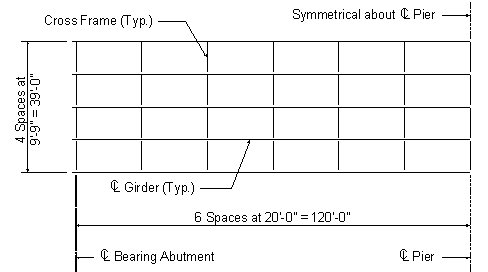
Figure 3-3 Framing Plan
 |
Cross-frame Spacing A common rule of thumb, based on previous editions of the AASHTO Specifications, is to use a maximum cross-frame spacing of 25 feet. For this design example, a cross-frame spacing of 20 feet is used because it facilitates a reduction in the required flange thicknesses in the girder section at the pier. This spacing also affects constructibility checks for stability before the deck is cured. Currently, stay-in-place forms should not be considered to provide adequate bracing to the top flange. |
The following units are defined for use in this design example:
![]()


Design criteria:
| Number of spans: | ||
| Span length: | ||
| Skew angle: | ||
| Number of girders: | ||
| Girder spacing: | ||
| Deck overhang: | ||
| Cross-frame spacing: | S6.7.4 | |
| Web yield strength: | STable 6.4.1-1 | |
| Flange yield strength: | STable 6.4.1-1 | |
| Concrete 28-day compressive strength: | S5.4.2.1 & STable C5.4.2.1-1 | |
| Reinforcement strength: | S5.4.3 & S6.10.3.7 | |
| Total deck thickness: | ||
| Effective deck thickness: | ||
| Total overhang thickness: | ||
| Effective overhang thickness: | ||
| Steel density: | STable 3.5.1-1 | |
| Concrete density: | STable 3.5.1-1 | |
| Additional miscellaneous dead load (per girder): | ||
| Stay-in-place deck form weight: | ||
| Parapet weight (each): | ||
| Future wearing surface: | STable 3.5.1-1 | |
| Future wearing surface thickness: | ||
| Deck width: | ||
| Roadway width: | ||
| Haunch depth (from top of web): | ||
| Average Daily Truck Traffic (Single-Lane): |
For this design example, transverse stiffeners will be designed in Step 3.12. In addition, a bolted field splice will be designed in Step 4, shear connectors will be designed in Step 5.1, bearing stiffeners will be designed in Step 5.2, welded connections will be designed in Step 5.3, cross-frames are described in Step 5.4, and an elastomeric bearing will be designed in Step 6. Longitudinal stiffeners will not be used, and a deck pouring sequence will not be considered in this design example.
Design factors from AASHTO LRFD Bridge Design Specifications:
Load factors:
STable 3.4.1-1 & STable 3.4.1-2
| Limit State | Load Factors | ||||||
| DC | DW | LL | IM | WS | WL | EQ | |
| Strength I | 1.25 | 1.50 | 1.75 | 1.75 | - | - | - |
| Service II | 1.00 | 1.00 | 1.30 | 1.30 | - | - | - |
| Fatique | - | - | 0.75 | 0.75 | - | - | - |
Table 3-1 Load Combinations and Load Factors
The abbreviations used in Table 3-1 are as defined in S3.3.2.
The extreme event limit state (including earthquake load) is generally not considered for a steel girder design.
Resistance factors:
S6.5.4.2
| Resistance Factor | |
| Type of Resistance | Resistance Factor , Φ |
| For flexure | Φf = 1.00 |
| For shear | Φv= 1.00 |
| For axial compression | Φc= 0.90 |
Table 3-2 Resistance Factors
 |
Multiple Presence Factors Multiple presence factors are described in S3.6.1.1.2. They are already included in the computation of live load distribution factors, as presented in S4.6.2.2. An exception, however, is that they must be included when the live load distribution factor for an exterior girder is computed assuming that the cross section deflects and rotates as a rigid cross section, as presented in S4.6.2.2.2d. Since S3.6.1.1.2 states that the effects of the multiple presence factor are not to be applied to the fatigue limit state, all emperically determined distribution factors for one-lane loaded that are applied to the single fatigue truck must be divided by 1.20 (that is, the multiple presence factor for one lane loaded). In addition, for distribution factors computed using the lever rule or based on S4.6.2.2.2d, the 1.20 factor should not be included when computing the distribution factor for one-lane loaded for the fatigue limit state. It should also be noted that the multiple presence factor still applies to the distribution factors for one-lane loaded for strength limit states. |
Dynamic load allowance:
STable 3.6.2.1-1
| Dynamic Load Allowance | |
| Limit State | Dynamic Load Allowance, IM |
| Fatigue and Fracture Limit State |
15% |
| All Other Limit States | 33% |
Table 3-3 Dynamic Load Allowance
Dynamic load allowance is the same as impact. The term "impact" was used in previous editions of the AASHTO Specifications. However, the term "dynamic load allowance" is used in the AASHTO LRFD Bridge Design Specifications.
Design Step 3.2 - Select Trial Girder Section
Before the dead load effects can be computed, a trial girder section must be selected. This trial girder section is selected based on previous experience and based on preliminary design. For this design example, the trial girder section presented in Figure 3-4 will be used. Based on this trial girder section, section properties and dead load effects will be computed. Then specification checks will be performed to determine if the trial girder section successfully resists the applied loads. If the trial girder section does not pass all specification checks or if the girder optimization is not acceptable, then a new trial girder section must be selected and the design process must be repeated.
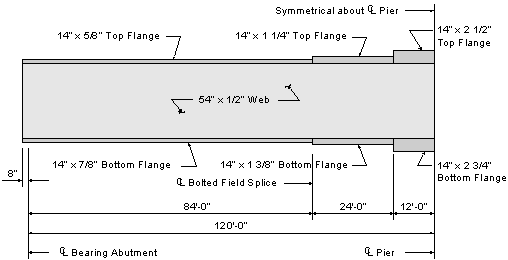
Figure 3-4 Plate Girder Elevation
For this design example, the 5/8" top flange thickness in the positive moment region was used to optimize the plate girder. It also satisfies the requirements of S6.7.3. However, it should be noted that some state requirements and some fabricator concerns may call for a 3/4" minimum flange thickness. In addition, the AASHTO/NSBA Steel Bridge Collaboration Document "Guidelines for Design for Constructibility" recommends a 3/4" minimum flange thickness.
 |
Girder Depth The minimum girder depth is specified in STable 2.5.2.6.3-1. An estimate of the optimum girder depth can be obtained from trial runs using readily available design software. The web depth may be varied by several inches more or less than the optimum without significant cost penalty. |
 |
Web Thickness A "nominally stiffened" web (approximately 1/16 inch thinner than "unstiffened") will generally provide the least cost alternative or very close to it. However, for web depths of approximately 50 inches or less, unstiffened webs may be more economical. |
 |
Plate Transitions A common rule of thumb is to use no more than three plates (two shop splices) in the top or bottom flange of field sections up to 130 feet long. In some cases, a single flange plate size can be carried through the full length of the field section. |
 |
Flange Widths Flange widths should remain constant within field sections. The use of constant flange widths simplifies construction of the deck. The unsupported length in compression of the shipping piece divided by the minimum width of the compression flange in that piece should be less than approximately 85. |
 |
Flange Plate Transitions It is good design practice to reduce the flange cross-sectional area by no more than approximately one-half of the area of the heavier flange plate. This reduces the build-up of stress at the transition. |
The above tips are presented to help bridge designers in developing an economical steel girder for most steel girder designs. Other design tips are available in various publications from the American Institute of Steel Construction (AISC) and from steel fabricators.
Design Step 3.3 - Compute Section Properties
Since the superstructure is composite, several sets of section properties must be computed. The initial dead loads (or the noncomposite dead loads) are applied to the girder-only section. The superimposed dead loads are applied to the composite section based on a modular ratio of 3n or n, whichever gives the higher stresses.
S6.10.3.1
S6.10.3.1.1b
 |
Modular Ratio As specified in S6.10.3.1.1b, for permanent loads assumed to be applied to the long-term composite section, the slab area shall be transformed by using a modular ratio of 3n or n, whichever gives the higher stresses. Using a modular ratio of 3n for the superimposed dead loads always gives higher stresses in the steel section. Using a modular ratio of n typically gives higher stresses in the concrete deck, except in the moment reversal regions where the selection of 3n vs. n can become an issue in determining the maximum stress in the deck. |
The live loads are applied to the composite section based on a modular ratio of n.
For girders with shear connectors provided throughout their entire length and with slab reinforcement satisfying the provisions of S6.10.3.7, stresses due to loads applied to the composite section for service and fatigue limit states may be computed using the composite section assuming the concrete slab to be fully effective for both positive and negative flexure.
S6.6.1.2.1 & S6.10.5.1
Therefore, for this design example, the concrete slab will be assumed to be fully effective for both positive and negative flexure for service and fatigue limit states.
For this design example, the interior girder controls. In general, both the exterior and interior girders must be considered, and the controlling design is used for all girders, both interior and exterior.
For this design example, only the interior girder design is presented. However, for the exterior girder, the computation of the live load distribution factors and the moment and shear envelopes are also presented.
For the design of an exterior girder, the composite section properties must be computed in accordance with S4.6.2.6.
The modular ratio is computed as follows:

STable 3.5.1-1
S5.4.2.1 & STable C5.4.2.1-1

S5.4.2.4
S6.4.1

Therefore, use n = 8.
In lieu of the above computations, the modular ratio can also be obtained from S6.10.3.1.1b. The above computations are presented simply to illustrate the process. Both the above computations and S6.10.3.1.1b result in a modular ratio of 8.
S6.10.3.1.1b
The effective flange width is computed as follows:
S4.6.2.6
For interior beams, the effective flange width is taken as the least of:
One-quarter of the effective span length:
Assume that the minimum, controlling effective span length equals approximately 60 feet (over the pier).

12.0 times the average thickness of the slab, plus the greater of web thickness or one-half the width of the top flange of the girder:
The average spacing of adjacent beams:

Therefore, the effective flange width is:
or
Based on the concrete deck design example, the total area of longitudinal deck reinforcing steel in the negative moment region is computed as follows:
 |
Slab Haunch For this design example, the slab haunch is 3.5 inches throughout the length of the bridge. That is, the bottom of the slab is located 3.5 inches above the top of the web. For this design example, this distance is used in computing the location of the centroid of the slab. However, the area of the haunch is not considered in the section properties. Some states and agencies assume that the slab haunch is zero when computing the section properties. If the haunch depth is not known, it is conservative to assume that the haunch is zero. If the haunch varies, it is reasonable to use either the minimum value or an average value. |
Based on the trial plate sizes shown in Figure 3-4, the noncomposite and composite section properties for the positive moment region are computed as shown in the following table. The distance to the centroid is measured from the bottom of the girder.
| Positive Moment Region Section Properties | ||||||
| Section | Area, A (Inches2) | Centroid, d (Inches) | A*d (Inches3) | Io (Inches4) | A*y2 (Inches4) | Itotal (Inches4) |
| Girder only: | ||||||
| Top flange | 8.750 | 55.188 | 482.9 | 0.3 | 7530.2 | 7530.5 |
| Web | 27.000 | 27.875 | 752.6 | 6561.0 | 110.5 | 6671.5 |
| Bottom flange | 12.250 | 0.438 | 5.4 | 0.8 | 7912.0 | 7912.7 |
| Total | 48.000 | 25.852 | 1240.9 | 6562.1 | 15552.7 | 22114.8 |
| Composite (3n): | ||||||
| Girder | 48.000 | 25.852 | 1240.9 | 22114.8 | 11134.4 | 33249.2 |
| Slab | 34.333 | 62.375 | 2141.5 | 183.1 | 15566.5 | 15749.6 |
| Total | 82.333 | 41.082 | 3382.4 | 22297.9 | 26700.8 | 48998.7 |
| Composite (n): | ||||||
| Girder | 48.000 | 25.852 | 1240.9 | 22114.8 | 29792.4 | 51907.2 |
| Slab | 103.000 | 62.375 | 6424.6 | 549.3 | 13883.8 | 14433.2 |
| Total | 151.000 | 50.765 | 7665.5 | 22664.1 | 43676.2 | 66340.3 |
| Section | ybotgdr (Inches) | ytopgdr (Inches) | ytopslab(Inches) | Sbotgdr (Inches3) | Stopgdr (Inches3) | Stopslab(Inches3) |
| Girder only | 25.852 | 29.648 | --- | 855.5 | 745.9 | --- |
| Composite (3n) | 41.082 | 14.418 | 25.293 | 1192.7 | 3398.4 | 1937.2 |
| Composite (n) | 50.765 | 4.735 | 15.610 | 1306.8 | 14010.3 | 4249.8 |
Table 3-4 Positive Moment Region Section Properties
Similarly, the noncomposite and composite section properties for the negative moment region are computed as shown in the following table. The distance to the centroid is measured from the bottom of the girder.
For the strength limit state, since the deck concrete is in tension in the negative moment region, the deck reinforcing steel contributes to the composite section properties and the deck concrete does not.
As previously explained, for this design example, the concrete slab will be assumed to be fully effective for both positive and negative flexure for service and fatigue limit states.
S6.6.1.2.1 & S6.10.5.1
| Negative Moment Region Section Properties | ||||||
| Section | Area, A (Inches2) | Centroid, d (Inches) | A*d (Inches3) | Io (Inches4) | A*y2 (Inches4) | Itotal (Inches4) |
| Girder only: | ||||||
| Top flange | 35.000 | 58.000 | 2030.0 | 18.2 | 30009.7 | 30027.9 |
| Web | 27.000 | 29.750 | 803.3 | 6561.0 | 28.7 | 6589.7 |
| Bottom flange | 38.500 | 1.375 | 52.9 | 24.3 | 28784.7 | 28809.0 |
| Total | 100.500 | 28.718 | 2886.2 | 6603.5 | 58823.1 | 65426.6 |
| Composite (deck concrete using 3n): | ||||||
| Girder | 100.500 | 28.718 | 2886.2 | 65426.6 | 8226.9 | 73653.5 |
| Slab | 34.333 | 64.250 | 2205.9 | 183.1 | 24081.6 | 24264.7 |
| Total | 134.833 | 37.766 | 5092.1 | 65609.7 | 32308.5 | 97918.3 |
| Composite (deck concrete using n): | ||||||
| Girder | 100.500 | 28.718 | 2886.2 | 65426.6 | 32504.5 | 97931.2 |
| Slab | 103.000 | 64.250 | 6617.8 | 549.3 | 31715.6 | 32264.9 |
| Total | 203.500 | 46.702 | 9503.9 | 65976.0 | 64220.1 | 130196.1 |
| Composite (deck reinforcement only): | ||||||
| Girder | 100.500 | 28.718 | 2886.2 | 65426.6 | 1568.1 | 66994.7 |
| Deck reinf. | 12.772 | 63.750 | 814.2 | 0.0 | 12338.7 | 12338.7 |
| Total | 113.272 | 32.668 | 3700.4 | 65426.6 | 13906.7 | 79333.4 |
| Section | ybotgdr (Inches) | ytopgdr (Inches) | ydeck (Inches) | Sbotgdr (Inches3) | Stopgdr (Inches3) | Sdeck (Inches3) |
| Girder only | 28.718 | 30.532 | --- | 2278.2 | 2142.9 | --- |
| Composite (3n) | 37.766 | 21.484 | 30.484 | 2592.8 | 4557.7 | 3212.1 |
| Composite (n) | 46.702 | 12.548 | 21.548 | 2787.8 | 10376.2 | 6042.3 |
| Composite (rebar) | 32.668 | 26.582 | 31.082 | 2428.5 | 2984.5 | 2552.4 |
Table 3-5 Negative Moment Region Section Properties
Design Step 3.4 - Compute Dead Load Effects
The girder must be designed to resist the dead load effects, as well as the other load effects. The dead load components consist of some dead loads that are resisted by the noncomposite section, as well as other dead loads that are resisted by the composite section. In addition, some dead loads are factored with the DC load factor and other dead loads are factored with the DW load factor. The following table summarizes the various dead load components that must be included in the design of a steel girder.
| Dead Load Components | ||
| Resisted by | Type of Load Factor | |
| DC | DW | |
| Noncomposite section |
|
|
| Composite section |
|
|
Table 3-6 Dead Load Components
For the steel girder, the dead load per unit length varies due to the change in plate sizes. The moments and shears due to the weight of the steel girder can be computed using readily available analysis software. Since the actual plate sizes are entered as input, the moments and shears are computed based on the actual, varying plate sizes.
For the concrete deck, the dead load per unit length for an interior girder is computed as follows:
For the concrete haunch, the dead load per unit length varies due to the change in top flange plate sizes. The moments and shears due to the weight of the concrete haunch can be computed using readily available analysis software. Since the top flange plate sizes are entered as input, the moments and shears due to the concrete haunch are computed based on the actual, varying haunch thickness.
For the stay-in-place forms, the dead load per unit length is computed as follows:
For the miscellaneous dead load (including cross-frames, stiffeners, and other miscellaneous structural steel), the dead load per unit length is assumed to be as follows:
For the concrete parapets, the dead load per unit length is computed as follows, assuming that the superimposed dead load of the two parapets is distributed uniformly among all of the girders:
S4.6.2.2.1
Although S4.6.2.2.1 specifies that permanent loads of and on the deck may be distributed uniformly among the beams, some states assign a larger percentage of the barrier loads to the exterior girders.
For the future wearing surface, the dead load per unit length is computed as follows, assuming that the superimposed dead load of the future wearing surface is distributed uniformly among all of the girders:
S4.6.2.2.1
Since the plate girder and its section properties are not uniform over the entire length of the bridge, an analysis must be performed to compute the dead load moments and shears. Such an analysis can be performed using one of various computer programs.
 |
Need for Revised Analysis It should be noted that during the optimization process, minor adjustments can be made to the plate sizes and transition locations without needing to recompute the analysis results. However, if significant adjustments are made, such that the moments and shears would change significantly, then a revised analysis is required. |
The following two tables present the unfactored dead load moments and shears, as computed by an analysis computer program (AASHTO Opis software). Since the bridge is symmetrical, the moments and shears in Span 2 are symmetrical to those in Span 1.
| Location in Span 1 | Steel girder | Concrete deck & haunches | Other dead loads acting on girder alone | Concrete parapets | Future wearing surface |
| 1.0L | -421.5 | -2418.3 | -357.1 | -436.1 | -528.2 |
| 0.9L | -244.0 | -1472.0 | -216.9 | -255.0 | -308.9 |
| 0.8L | -107.2 | -679.7 | -99.9 | -104.5 | -126.6 |
| 0.7L | -2.5 | -43.1 | -6.2 | 15.5 | 18.8 |
| 0.6L | 73.6 | 436.6 | 64.4 | 104.9 | 127.1 |
| 0.5L | 124.4 | 758.4 | 111.7 | 163.8 | 198.4 |
| 0.4L | 150.0 | 922.4 | 135.8 | 192.2 | 232.7 |
| 0.3L | 150.3 | 928.6 | 136.7 | 189.9 | 230.1 |
| 0.2L | 125.5 | 776.9 | 114.3 | 157.2 | 190.4 |
| 0.1L | 75.4 | 467.4 | 68.8 | 93.9 | 113.7 |
| 0.0L | 0.0 | 0.0 | 0.0 | 0.0 | 0.0 |
Table 3-7 Dead Load Moments (Kip-feet)
| Location in Span 1 | Steel girder | Concrete deck & haunches | Other dead loads acting on girder alone | Concrete parapets | Future wearing surface |
| 1.0L | -16.84 | -85.18 | -12.65 | -16.36 | -19.82 |
| 0.9L | -12.74 | -72.52 | -10.72 | -13.82 | -16.74 |
| 0.8L | -10.06 | -59.54 | -8.78 | -11.27 | -13.65 |
| 0.7L | -7.39 | -46.55 | -6.85 | -8.73 | -10.57 |
| 0.6L | -5.29 | -33.40 | -4.91 | -6.18 | -7.49 |
| 0.5L | -3.18 | -20.24 | -2.98 | -3.63 | -4.40 |
| 0.4L | -1.08 | -7.09 | -1.04 | -1.09 | -1.32 |
| 0.3L | 1.02 | 6.06 | 0.89 | 1.46 | 1.77 |
| 0.2L | 3.12 | 19.22 | 2.83 | 4.00 | 4.85 |
| 0.1L | 5.23 | 32.37 | 4.76 | 6.55 | 7.93 |
| 0.0L | 7.33 | 45.53 | 6.70 | 9.10 | 11.02 |
Table 3-8 Dead Load Shears (kips)
Design Step 3.5 - Compute Live Load Effects
 |
LRFD Live Load There are several differences between the live load used in Allowable Stress Design (ASD) or Load Factor Design (LFD) and the live load used in Load and Resistance Factor Design (LRFD). Some of the more significant differences are:
For additional information about the live load used in LRFD, refer to S3.6 and C3.6. |
The girder must also be designed to resist the live load effects. The live load consists of an HL-93 loading. Similar to the dead load, the live load moments and shears for an HL-93 loading can be obtained from an analysis computer program.
S3.6.1.2
Based on Table 3-3, for all limit states other than fatigue and fracture, the dynamic load allowance, IM, is as follows:
S3.6.2.1
The live load distribution factors for moment for an interior girder are computed as follows:
S4.6.2.2.2
First, the longitudinal stiffness parameter, Kg, must be computed:
S4.6.2.2.1
| Longitudinal Stiffness Parameter, Kg | ||||
| Region A (Pos. Mom.) |
Region B (Intermediate) |
Region C (At Pier) |
Weighted Average | |
| Length (Feet) | 84 | 24 | 12 | |
| n | 8 | 8 | 8 | |
| I (Inches4) | 22,114.8 | 34,639.8 | 65,426.6 | |
| A (Inches2) | 48.000 | 63.750 | 100.500 | |
| eg (Inches) | 36.523 | 35.277 | 35.532 | |
| Kg (Inches4) | 689,147 | 911,796 | 1,538,481 | 818,611 |
| * Weighted average is estimated based on length of each region | ||||
Table 3-9 Longitudinal Stiffness Parameter
After the longitudinal stiffness parameter is computed, STable 4.6.2.2.1-1 is used to find the letter corresponding with the superstructure cross section. The letter corresponding with the superstructure cross section in this design example is "a."
If the superstructure cross section does not correspond with any of the cross sections illustrated in STable 4.6.2.2.1-1, then the bridge should be analyzed as presented in S4.6.3.
Based on cross section "a," STables 4.6.2.2.2b-1 and 4.6.2.2.2.3a-1 are used to compute the distribution factors for moment and shear, respectively.
S4.6.2.2.1
Check the range of applicability as follows:
STable 4.6.2.2.2b-1


For one design lane loaded, the distribution of live load per lane for moment in interior beams is as follows:
STable 4.6.2.2.2b-1
lanes
For two or more design lanes loaded, the distribution of live load per lane for moment in interior beams is as follows:
STable 4.6.2.2.2b-1
lanes
The live load distribution factors for shear for an interior girder are computed in a similar manner. The range of applicability is similar to that for moment.
STable 4.6.2.2.3a-1
For one design lane loaded, the distribution of live load per lane for shear in interior beams is as follows:
STable 4.6.2.2.3a-1
lanes
For two or more design lanes loaded, the distribution of live load per lane for shear in interior beams is as follows:
STable 4.6.2.2.3a-1
lanes
Since this bridge has no skew, the skew correction factor does not need to be considered for this design example.
S4.6.2.2.2e, S4.6.2.2.3c
This design example is based on an interior girder. However, for illustrative purposes, the live load distribution factors for an exterior girder are computed below, as follows:
S4.6.2.2.2
The distance, de, is defined as the distance between the web centerline of the exterior girder and the interior edge of the curb. For this design example, based on Figure 3-2:
Check the range of applicability as follows:
STable 4.6.2.2.2d-1

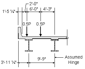
For one design lane loaded, the distribution of live load per lane for moment in exterior beams is computed using the lever rule, as follows:
STable 4.6.2.2.2d-1
Figure 3-5 Lever Rule
lanes
lanes (for strength limit state)
For two or more design lanes loaded, the distribution of live load per lane for moment in exterior beams is as follows:
STable 4.6.2.2.2d-1

lanes
The live load distribution factors for shear for an exterior girder are computed in a similar manner. The range of applicability is similar to that for moment.
STable 4.6.2.2.3b-1
For one design lane loaded, the distribution of live load per lane for shear in exterior beams is computed using the lever rule, as illustrated in Figure 3-5 and as follows:
STable 4.6.2.2.3b-1
lanes
lanes (for strength limit state)
For two or more design lanes loaded, the distribution of live load per lane for shear in exterior beams is as follows:
STable 4.6.2.2.3b-1

lanes
In beam-slab bridge cross-sections with diaphragms or cross-frames, the distribution factor for the exterior beam can not be taken to be less than that which would be obtained by assuming that the cross-section deflects and rotates as a rigid cross-section. CEquation 4.6.2.2.2d-1 provides one approximate approach to satisfy this requirement. The multiple presence factor provisions of S3.6.1.1.2 must be applied when this equation is used.
S4.6.2.2.2d
Since this bridge has no skew, the skew correction factor does not need to be considered for this design example.
S4.6.2.2.2e, S4.6.2.2.3c
The following table presents the unfactored maximum positive and negative live load moments and shears for HL-93 live loading for interior beams, as computed using an analysis computer program. These values include the live load distribution factor, and they also include dynamic load allowance. Since the bridge is symmetrical, the moments and shears in Span 2 are symmetrical to those in Span 1.
| Live Load Effects (for Interior Beams) | |||||||||||
| Location in Span 1 | Maximum positive moment (K-ft) | Maximum negative moment (K-ft) | Maximum positive shear (kips) | Maximum negative shear (kips) | |||||||
| 1.0L | 983 | -2450 | 35.8 | -131.4 | |||||||
| 0.9L | 865 | -1593 | 33.0 | -118.5 | |||||||
| 0.8L | 1006 | -1097 | 32.1 | -105.1 | |||||||
| 0.7L | 1318 | -966 | 33.5 | -91.1 | |||||||
| 0.6L | 1628 | -966 | 37.1 | -76.7 | |||||||
| 0.5L | 1857 | -968 | 42.5 | -62.2 | |||||||
| 0.4L | 1908 | -905 | 49.6 | -47.8 | |||||||
| 0.3L | 1766 | -777 | 61.0 | -36.4 | |||||||
| 0.2L | 1422 | -583 | 76.6 | -29.1 | |||||||
| 0.1L | 836 | -324 | 93.7 | -28.7 | |||||||
| 0.0L | 0 | 0 | 110.5 | -33.8 | |||||||
Table 3-10 Live Load Effects (for Interior Beams)
The design live load values for HL-93 loading, as presented in the previous table, are computed based on the product of the live load effect per lane and live load distribution factor. These values also include the effects of dynamic load allowance. However, it is important to note that the dynamic load allowance is applied only to the design truck or tandem. The dynamic load allowance is not applied to pedestrian loads or to the design lane load.
S3.6.1, S3.6.2, S4.6.2.2
Design Step 3.6 - Combine Load Effects
After the load factors and load combinations have been established (see Design Step 3.1), the section properties have been computed (see Design Step 3.3), and all of the load effects have been computed (see Design Steps 3.4 and 3.5), the force effects must be combined for each of the applicable limit states.
For this design example, η equals 1.00. (For more detailed information about η, refer to Design Step 1.)
S1.3
Based on the previous design steps, the maximum positive moment (located at 0.4L) for the Strength I Limit State is computed as follows:
S3.4.1
Similarly, the maximum stress in the top of the girder due to positive moment (located at 0.4L) for the Strength I Limit State is computed as follows:
Noncomposite dead load:
Parapet dead load (composite):


Future wearing surface dead load (composite):


Live load (HL-93) and dynamic load allowance:

Multiplying the above stresses by their respective load factors and adding the products results in the following combined stress for the Strength I Limit State:
S3.4.1
Similarly, all of the combined moments, shears, and flexural stresses can be computed at the controlling locations. A summary of those combined load effects for an interior beam is presented in the following three tables, summarizing the results obtained using the procedures demonstrated in the above computations.
| Combined Effects at Location of Maximum Positive Moment Summary of Unfactored Values: |
||||
| Loading | Moment (K-ft) | fbotgdr (ksi) | ftopgdr (ksi) | ftopslab (ksi) |
| Noncomposite DL | 1208 | 16.95 | -19.44 | 0.00 |
| Parapet DL | 192 | 1.93 | -0.68 | -0.05 |
| FWS DL | 233 | 2.34 | -0.82 | -0.06 |
| LL - HL-93 | 1908 | 17.52 | -1.63 | -0.67 |
| LL - Fatigue | 563 | 5.17 | -0.48 | -0.20 |
| Summary of Factored Values: | ||||
| Limit State | Moment (K-ft) | fbotgdr (ksi) | ftopgdr (ksi) | ftopslab (ksi) |
| Strength I | 5439 | 57.77 | -29.24 | -1.33 |
| Service II | 4114 | 44.00 | -23.06 | -0.99 |
| Fatigue | 422 | 3.87 | -0.36 | -0.15 |
Table 3-11 Combined Effects at Location of Maximum Positive Moment
As shown in the above table, the Strength I Limit State elastic stress in the bottom of the girder exceeds the girder yield stress. However, for this design example, this value is not used because of the local yielding that occurs at this section.
| Combined Effects at Location of Maximum Negative Moment | |||||||
| Summary of Unfactored Values (Assuming Concrete Not Effective): | |||||||
| Loading | Moment (K-ft) | fbotgdr (ksi) | ftopgdr (ksi) | fdeck (ksi) | |||
| Noncomposite DL | -3197 | -16.84 | 17.90 | 0.00 | |||
| Parapet DL | -436 | -2.15 | 1.75 | 2.05 | |||
| FWS DL | -528 | -2.61 | 2.12 | 2.48 | |||
| LL - HL-93 | -2450 | -12.11 | 9.85 | 11.52 | |||
| Summary of Unfactored Values (Assuming Concrete Effective): | |||||||
| Loading | Moment (K-ft) | fbotgdr (ksi) | ftopgdr (ksi) | fdeck (ksi) | |||
| Noncomposite DL | -3197 | -16.84 | 17.90 | 0.00 | |||
| Parapet DL | -436 | -2.02 | 1.15 | 0.07 | |||
| FWS DL | -528 | -2.44 | 1.39 | 0.08 | |||
| LL - HL-93 | -2450 | -10.55 | 2.83 | 0.61 | |||
| LL - Fatigue | -406 | -1.75 | 0.47 | 0.10 | |||
| Summary of Factored Values: | |||||||
| Limit State | Moment (K-ft) | fbotgdr (ksi) | ftopgdr (ksi) | fdeck (ksi) | |||
| Strength I* | -9621 | -48.84 | 44.99 | 26.44 | |||
| Service II** | -7346 | -35.01 | 24.12 | 0.94 | |||
| Fatigue ** | -305 | -1.31 | 0.35 | 0.08 | |||
Legend:
*Strength I Limit State stresses are based on section properties assuming the deck concrete is not effective, and fdeck is the stress in the deck reinforcing steel.
**Service II and Fatigue Limit State stresses are based on section properties assuming the deck concrete is effective, and fdeck is the stress in the deck concrete.
Table 3-12 Combined Effects at Location of Maximum Negative Moment
| Combined Effects at Location of Maximum Shear Summary of Unfactored Values: |
|
| Loading | Shear (kips) |
| Noncomposite DL | 114.7 |
| Parapet DL | 16.4 |
| FWS DL | 19.8 |
| LL - HL-93 | 131.4 |
| LL - Fatigue | 46.5 |
| Summary of Factored Values: | |
| Limit State | Shear (kips) |
| Strength I | 423.5 |
| Service II | 321.7 |
| Fatigue | 34.8 |
Table 3-13 Combined Effects at Location of Maximum Shear
Envelopes of the factored Strength I moments and shears are presented in the following two figures. Maximum and minimum values are presented, and values for both interior and exterior girders are presented. Based on these envelopes, it can be seen that the interior girder controls the design, and all remaining design computations are based on the interior girder.
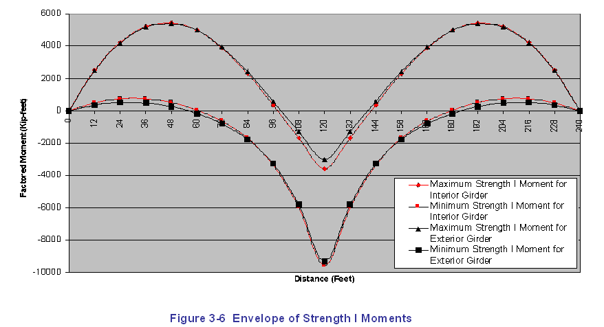
Figure 3-6 Envelope of Strength I Moments
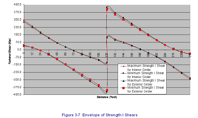
Figure 3-7 Envelope of Strength I Shears
Design Steps 3.7 through 3.17 consist of verifying the structural adequacy of critical beam locations using appropriate sections of the Specifications.
For this design example, two design sections will be checked for illustrative purposes. First, all specification checks for Design Steps 3.7 through 3.17 will be performed for the location of maximum positive moment, which is at 0.4L in Span 1. Second, all specification checks for these same design steps will be performed for the location of maximum negative moment and maximum shear, which is at the pier.
 |
Specification Check Locations For steel girder designs, specification checks are generally performed using a computer program at the following locations:
However, it should be noted that the maximum moment within a span may not necessarily occur at any of the above locations. |
The following specification checks are for the location of maximum positive moment, which is at 0.4L in Span 1, as shown in Figure 3-8.
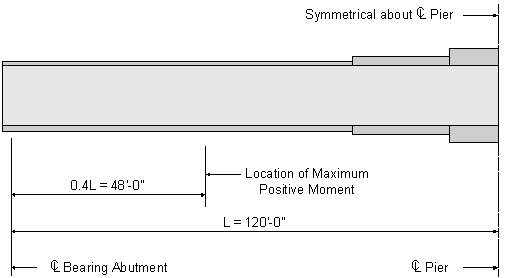
Figure 3-8 Location of Maximum Positive Moment
Design Step 3.7 - Check Section Proportion Limits - Positive Moment Region
Several checks are required to ensure that the proportions of the trial girder section are within specified limits.
S6.10.2
The first section proportion check relates to the general proportions of the section. The flexural components must be proportioned such that:
S6.10.2.1

OK
The second section proportion check relates to the web slenderness. For a section without longitudinal stiffeners, the web must be proportioned such that:
S6.10.2.2
For the Strength I limit state at 0.4L in Span 1 (the location of maximum positive moment):
S6.10.3.1.4a
(see Table 3-11 and explanation below table)
(see Table 3-11)
(see Figure 3-4)
(see Figure 3-4)
(see Figure 3-4)
C6.10.3.1.4a
(see Figure 3-4)
S6.4.1
and
OK
The third section proportion check relates to the flange proportions. The compression flanges on fabricated I-sections must be proportioned such that:
S6.10.2.3
(see Figure 3-4)
OK
According to C6.10.2.3, it is preferable for the flange width to be greater than or equal to 0.4Dc. In this case, the flange width is greater than both 0.3Dc and 0.4Dc, so this requirement is clearly satisfied.
C6.10.2.3
In addition to the compression flange check, the tension flanges on fabricated I-sections must be proportioned such that:
S6.10.2.3
(see Figure 3-4)
(see Figure 3-4)
OK
Design Step 3.8 - Compute Plastic Moment Capacity - Positive Moment Region
For composite sections, the plastic moment, Mp, is calculated as the first moment of plastic forces about the plastic neutral axis.
S6.10.3.1.3
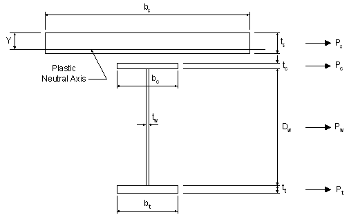
Figure 3-9 Computation of Plastic Moment Capacity for Positive Bending Sections
For the tension flange:
SAppendix A6.1


For the web:


For the compression flange:


For the slab:


The forces in the longitudinal reinforcement may be conservatively neglected.
C6.10.3.1.3
Check the location of the plastic neutral axis, as follows:
SAppendix A6.1
Therefore, the plastic neutral axis is located within the slab.
STable A6.1-1
Check that the position of the plastic neutral axis, as computed above, results in an equilibrium condition in which there is no net axial force.
OK
The plastic moment, Mp, is computed as follows, where d is the distance from an element force (or element neutral axis) to the plastic neutral axis:
STable A6.1-1
Design Step 3.9 - Determine if Section is Compact or Noncompact - Positive Moment Region
The next step in the design process is to determine if the section is compact or noncompact. This, in turn, will determine which formulae should be used to compute the flexural capacity of the girder.
Where the specified minimum yield strength does not exceed 70.0 ksi, and the girder has a constant depth, and the girder does not have longitudinal stiffeners or holes in the tension flange, then the first step is to check the compact-section web slenderness provisions, as follows:
S6.10.4.1.1
S6.10.4.1.2
Since the plastic neutral axis is located within the slab,
Therefore the web is deemed compact. Since this is a composite section in positive flexure, the flexural resistance is computed as defined by the composite compact-section positive flexural resistance provisions of S6.10.4.2.2.
S6.10.4.1.2
For composite sections in positive flexure in their final condition, the provisions of S6.10.4.1.3, S6.10.4.1.4, S6.10.4.1.6a, S6.10.4.1.7, and S6.10.4.1.9 are considered to be automatically satisfied.
The section is therefore considered to be compact.
CFigure 6.10.4-1
Design Step 3.10 - Design for Flexure - Strength Limit State - Positive Moment Region
Since the section was determined to be compact, and since it is a composite section in the positive moment region, the flexural resistance is computed in accordance with the provisions of S6.10.4.2.2.
This is neither a simple span nor a continuous span with compact sections in the negative flexural region over the interior supports. (This will be proven in the negative flexure region computations of this design example.) Therefore, the nominal flexural resistance is determined using the following equation, based on the approximate method:
SFigure C6.10.4-1
S6.10.4.2.2a
All design sections of this girder are homogenous. That is, the same structural steel is used for the top flange, the web, and the bottom flange. Therefore, the hybrid factor, Rh, is as follows:
S6.10.4.3.1
The yield moment, My, is computed as follows:
SAppendix A6.2

For the bottom flange:
For the top flange:
The yield moment, My, is the lesser value computed for both flanges. Therefore, My is determined as follows:
SAppendix A6.2
Therefore, for the positive moment region of this design example, the nominal flexural resistance is computed as follows:
S6.10.4.2.2a
In addition, the nominal flexural resistance can not be taken to be greater than the applicable value of Mn computed from either SEquation 6.10.4.2.2a-1 or 6.10.4.2.2a-2.
S6.10.4.2.2a

S6.10.4.2.2b
for Fy = 50 ksi


Therefore
S6.10.4.2.2a
Therefore, use
The ductility requirement in S6.10.4.2.2b is checked as follows:
S6.10.4.2.2b

OK
The factored flexural resistance, Mr, is computed as follows:
S6.10.4
S6.5.4.2
The positive flexural resistance at this design section is checked as follows:
S1.3.2.1
or in this case:
For this design example,
As computed in Design Step 3.6,
Therefore
OK
 |
Available Plate Thicknesses Based on the above computations, the flexural resistance is approximately 10% greater than the factored design moment, yielding a slightly conservative design. This degree of conservatism can generally be adjusted by changing the plate dimensions as needed. However, for this design example, the web dimensions and the flange width were set based on the girder design requirements at the pier. In addition, the flange thicknesses could not be reduced any further due to limitations in plate thicknesses or because such a reduction would result in a specification check failure. Available plate thicknesses can be obtained from steel fabricators. As a rule of thumb, the following plate thicknesses are generally available from steel fabricators:
|
Design Step 3.11 - Design for Shear - Positive Moment Region
Shear must be checked at each section of the girder. However, shear is minimal at the location of maximum positive moment, and it is maximum at the pier.
Therefore, for this design example, the required shear design computations will be presented later for the girder design section at the pier.
S6.10.7
It should be noted that in end panels, the shear is limited to either the shear yield or shear buckling in order to provide an anchor for the tension field in adjacent interior panels. Tension field is not allowed in end panels. The design procedure for shear in the end panel is presented in S6.10.7.3.3c.
S6.10.7.3.3c
Design Step 3.12 - Design Transverse Intermediate Stiffeners - Positive Moment Region
The girder in this design example has transverse intermediate stiffeners. Transverse intermediate stiffeners are used to increase the shear resistance of the girder.
As stated above, shear is minimal at the location of maximum positive moment but is maximum at the pier. Therefore, the required design computations for transverse intermediate stiffeners will be presented later for the girder design section at the pier.
S6.10.8.1
Design Step 3.14 - Design for Flexure - Fatigue and Fracture Limit State - Positive Moment Region
Load-induced fatigue must be considered in a plate girder design. Fatigue considerations for plate girders may include:
- Welds connecting the shear studs to the girder.
- Welds connecting the flanges and the web.
- Welds connecting the transverse intermediate stiffeners to the girder.
The specific fatigue considerations depend on the unique characteristics of the girder design. Specific fatigue details and detail categories are explained and illustrated in STable 6.6.1.2.3-1 and in SFigure 6.6.1.2.3-1.
For this design example, fatigue will be checked for the fillet-welded connection of the transverse intermediate stiffeners to the girder. This detail corresponds to Illustrative Example 6 in SFigure 6.6.1.2.3-1, and it is classified as Detail Category C' in STable 6.6.1.2.3-1.
S6.6.1
STable 6.6.1.2.3-1
SFigure 6.6.1.2.3-1
For this design example, the fillet-welded connection of the transverse intermediate stiffeners will be checked at the location of maximum positive moment. The fatigue detail is located at the inner fiber of the tension flange, where the transverse intermediate stiffener is welded to the flange. However, for simplicity, the computations will conservatively compute the fatigue stress at the outer fiber of the tension flange.
The fatigue detail being investigated in this design example is illustrated in the following figure:
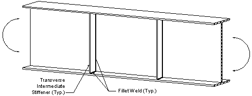
Figure 3-10 Load-Induced Fatigue Detail
The nominal fatigue resistance is computed as follows:
S6.6.1.2.5
for which:
STable 6.6.1.2.5-1
S6.6.1.2.5
STable 6.6.1.2.5-2
STable 6.6.1.2.5-3
S6.6.1.2.5
 |
Fatigue Resistance CTable 6.6.1.2.5-1 can be used to eliminate the need for some of the above fatigue resistance computations. The above computations are presented simply for illustrative purposes. |
The factored fatigue stress in the outer fiber of the tension flange at the location of maximum positive moment was previously computed in Table 3-11, as follows:
OK
In addition to the above fatigue detail check, fatigue requirements for webs must also be checked. These calculations will be presented later for the girder design section at the pier.
S6.10.6
Design Step 3.15 - Design for Flexure - Service Limit State - Positive Moment Region
The girder must be checked for service limit state control of permanent deflection. This check is intended to prevent objectionable permanent deflections due to expected severe traffic loadings that would impair rideability. Service II Limit State is used for this check.
The flange stresses for both steel flanges of composite sections must satisfy the following requirement:
S6.10.5
S6.10.5.2
The factored Service II flexural stress was previously computed in Table 3-11 as follows:

OK
In addition to the check for service limit state control of permanent deflection, the girder can also be checked for live load deflection. Although this check is optional for a concrete deck on steel girders, it is included in this design example.
Using an analysis computer program, the maximum live load deflection is computed to be the following:
S2.5.2.6.2
This maximum live load deflection is computed based on the following:
- All design lanes are loaded.
- All supporting components are assumed to deflect equally.
- For composite design, the design cross section includes the entire width of the roadway.
- The number and position of loaded lanes is selected to provide the worst effect.
- The live load portion of Service I Limit State is used.
- Dynamic load allowance is included.
- The live load is taken from S3.6.1.3.2.
S2.5.2.6.2
In the absence of other criteria, the deflection limit is as follows:
S2.5.2.6.2
OK
Design Step 3.16 - Design for Flexure - Constructibility Check - Positive Moment Region
The girder must also be checked for flexure during construction. The girder has already been checked in its final condition when it behaves as a composite section. The constructibility must also be checked for the girder prior to the hardening of the concrete deck when the girder behaves as a noncomposite section.
S6.10.3.2
As previously stated, a deck pouring sequence will not be considered in this design example. However, it is generally important to consider the effects of the deck pouring sequence in an actual design because it will often control the design of the top flange in the positive moment regions of composite girders.
The investigation of the constructibility of the girder begins with the the noncompact section compression-flange slenderness check, as follows:
S6.10.4.1.4
(see Figure 3-4)
(see Figure 3-4)
Therefore, the investigation proceeds with the noncompact section compression-flange bracing provisions of S6.10.4.1.9.
S6.10.4.1.9
The term, rt, is defined as the radius of gyration of a notional section comprised of the compression flange of the steel section plus one-third of the depth of the web in compression taken about the vertical axis.
For the noncomposite loads during construction:
(see Figure 3-4 and Table 3-4)


Therefore, the investigation proceeds with the noncomposite section lateral torsional buckling provisions of S6.10.4.2.6.
 |
Lateral Torsional Buckling Lateral torsional buckling can occur when the compression flange is not laterally supported. The laterally unsupported compression flange tends to buckle out-of-plane between the points of lateral support. Because the tension flange is kept in line, the girder section twists when it moves laterally. This behavior is commonly referred to as lateral torsional buckling. Lateral torsional buckling is generally most critical for the moments induced during the deck pouring sequence. If lateral torsional buckling occurs, the plastic moment resistance, Mp, can not be reached. Lateral torsional buckling is illustrated in the figure below. |
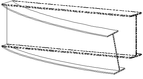
Figure 3-11 Lateral Torsional Buckling
The nominal flexural resistance of the compression flange is determined from the following equation:
S6.10.4.2.6a
S6.10.4.2.4a
The load-shedding factor, Rb, is computed as follows:
S6.10.4.3.2
for sections where Dc is greater than D/2

Therefore
Check if

Therefore:
For homogeneous section, Rh is taken as 1.0.
S6.10.4.3.1
The critical compression-flange local buckling stress, Fcr, is computed as follows:
S6.10.4.2.4a
without longitudinal web stiffeners


Therefore the nominal flexural resistance of the compression flange is determined from the following equation:
S6.10.4.2.4a
In addition, the nominal flexural resistance of the compression flange should not exceed the nominal flexural resistance based upon lateral-torsional buckling determined as follows:
S6.10.4.2.6a
Check if


Check if
(see Table 3-4)

Therefore:
S6.10.4.2.6a
The moment gradient correction factor, Cb, is computed as follows:
S6.10.4.2.5a
Use:
(based on analysis)
Therefore

S6.10.3.3.1

S6.10.4.2.6a


Therefore

S6.10.4.2.6a

Therefore, the provisions of SEquation 6.10.4.2.4a-2 control.

The factored flexural resistance, Fr, is computed as follows:
S6.10.4
S6.5.4.2

The factored construction stress in the compression flange is as follows:
(previously computed) OK
For the tension flange, the nominal flexural resistance, in terms of stress, is determined as follows:
S6.10.4.2.6b
where:
S6.10.4.3.2b
The factored flexural resistance, Fr, is computed as follows:
S6.10.4
S6.5.4.2
The factored construction stress in the tension flange is as follows:
OK
Therefore, the girder design section at the location of maximum positive moment satisfies the noncomposite section flexural resistance requirements for construction loads based upon lateral torsional buckling for both the compression flange and the tension flange.
In addition, composite girders, when they are not yet composite, must satisfy the following requirement during construction:
S6.10.3.2.2
for which:
for webs without longitudinal stiffeners
for webs without longitudinal stiffeners

(see Figure 3-4)
OK
In addition to checking the nominal flexural resistance during construction, the nominal shear resistance must also be checked. However, shear is minimal at the location of maximum positive moment, and it is maximum at the pier.
Therefore, for this design example, the nominal shear resistance for constructibility will be presented later for the girder design section at the pier.
S6.10.3.2.3
Design Step 3.17 - Check Wind Effects on Girder Flanges - Positive Moment Region
As stated in Design Step 3.3, for this design example, the interior girder controls and is being designed.
S6.10.3.5
Wind effects generally do not control a steel girder design, and they are generally considered for the exterior girders only. However, for this design example, wind effects will be presented later for the girder design section at the pier.
Specification checks have been completed for the location of maximum positive moment, which is at 0.4L in Span 1.
C6.10.3.5.2 & C4.6.2.7.1
Now the specification checks are repeated for the location of maximum negative moment, which is at the pier, as shown in Figure 3-12. This is also the location of maximum shear.
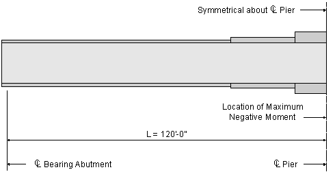
Figure 3-12 Location of Maximum Negative Moment
Design Step 3.7 - Check Section Proportion Limits - Negative Moment Region
Several checks are required to ensure that the proportions of the trial girder section are within specified limits.
S6.10.2
The first section proportion check relates to the general proportions of the section. The flexural components must be proportioned such that:
S6.10.2.1

OK
The second section proportion check relates to the web slenderness. For a section without longitudinal stiffeners, the web must be proportioned such that:
S6.10.2.2
At sections in negative flexure, using Dc of the composite section consisting of the steel section plus the longitudinal reinforcement is conservative.
C6.10.3.1.4a
 |
D c for Negative Flexure At sections in negative flexure, using Dc of the composite section consisting of the steel section plus the longitudinal reinforcement, as described in C6.10.3.1.4a, removes the dependency of Dc on the applied loading, which greatly simplifies subsequent load rating calculations. |
(see Figure 3-4 and Table 3-5)
(see Figure 3-4)
S6.4.1
and
OK
The third section proportion check relates to the flange proportions. The compression flanges on fabricated I-sections must be proportioned such that:
S6.10.2.3
(see Figure 3-4)
OK
According to C6.10.2.3, it is preferable for the flange width to be greater than or equal to 0.4Dc. In this case, the flange width is greater than both 0.3Dc and 0.4Dc, so this requirement is clearly satisfied.
C6.10.2.3
In addition to the compression flange check, the tension flanges on fabricated I-sections must be proportioned such that:
S6.10.2.3
(see Figure 3-4)
(see Figure 3-4)
OK
Design Step 3.8 - Compute Plastic Moment Capacity - Negative Moment Region
For composite sections, the plastic moment, Mp, is calculated as the first moment of plastic forces about the plastic neutral axis.
S6.10.3.1.3
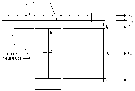
Figure 3-13 Computation of Plastic Moment Capacity for Negative Bending Sections
For the tension flange:
SAppendix A6.1


For the web:


For the compression flange:


For the longitudinal reinforcing steel in the top layer of the slab at the pier:


For the longitudinal reinforcing steel in the bottom layer of the slab at the pier:


Check the location of the plastic neutral axis, as follows:
SAppendix A6.1
Therefore the plastic neutral axis is located within the web.
STable A6.1-2
Since it will be shown in the next design step that this section is noncompact, the plastic moment is not used to compute the flexural resistance and therefore does not need to be computed.
Design Step 3.9 - Determine if Section is Compact or Noncompact - Negative Moment Region
The next step in the design process is to determine if the section is compact or noncompact. This, in turn, will determine which formulae should be used to compute the flexural capacity of the girder.
Where the specified minimum yield strength does not exceed 70.0 ksi, and the girder has a constant depth, and the girder does not have longitudinal stiffeners or holes in the tension flange, then the first step is to check the compact-section web slenderness provisions, as follows:
S6.10.4.1.1
S6.10.4.1.2
Since the plastic neutral axis is located within the web,


Therefore, the web does not qualify as compact. Since this is not a composite section in positive flexure, the investigation proceeds with the noncompact section compression-flange slenderness provisions of S6.10.4.1.4.
S6.10.4.1.4

Therefore, the investigation proceeds with the noncompact section compression-flange bracing provisions of S6.10.4.1.9.
S6.10.4.1.9
The term, rt, is defined as the radius of gyration of a notional section comprised of the compression flange of the steel section plus one-third of the depth of the web in compression taken about the vertical axis.
Based on previous computations,
Therefore, the investigation proceeds with the composite section lateral torsional buckling provisions of S6.10.4.2.5.
 |
Noncompact Sections Based on the previous computations, it was determined that the girder section at the pier is noncompact. Several steps could be taken to make this a compact section, such as increasing the web thickness or possibly modifying the flange thicknesses to decrease the value Dcp. However, such revisions may not be economical. |
Design Step 3.10 - Design for Flexure - Strength Limit State - Negative Moment Region
Since the section was determined to be noncompact and based on the computations in the previous design step, the nominal flexural resistance is computed based upon lateral torsional buckling.
S6.10.4.2.5
The nominal flexural resistance of the compression flange, in terms of stress, is determined from the following equation:
S6.10.4.2.5a
S6.10.4.2.4a
The load-shedding factor, Rb, is computed as follows:
S6.10.4.3.2
for sections where Dc is greater than D/2


Therefore
Check if

Therefore:
For homogeneous section, Rh is taken as 1.0.
S6.10.4.3.1
The critical compression-flange local buckling stress, Fcr, is computed as follows:
S6.10.4.2.4a
without longitudinal web stiffeners


Therefore the nominal flexural resistance of the compression flange is determined from the following equation:
S6.10.4.2.4a
In addition, the nominal flexural resistance of the compression flange should not exceed the nominal flexural resistance based upon lateral-torsional buckling determined as follows:
S6.10.4.2.5a
Check if


Therefore:
The moment gradient correction factor, Cb, is computed as follows:
SC6.10.4.2.5a
Use:
(based on analysis)
Therefore
Therefore
The factored flexural resistance, Fr, is computed as follows:
S6.10.4
S6.5.4.2
The negative flexural resistance at this design section is checked as follows:
S1.3.2.1
or in this case:
For this design example,
As computed in Design Step 3.6, the factored Strength I Limit State stress for the compression flange is as follows:
Therefore
OK
For the tension flange, the nominal flexural resistance, in terms of stress, is determined as follows:
S6.10.4.2.5b
where:
S6.10.4.3.2b
The factored flexural resistance, Fr, is computed as follows:
S6.10.4
S6.5.4.2
The negative flexural resistance at this design section is checked as follows:
S1.3.2.1
or in this case:
For this design example,
As computed in Design Step 3.6, the factored Strength I Limit State stress for the tension flange is as follows:
Therefore
OK
Therefore, the girder design section at the pier satisfies the flexural resistance requirements for both the compression flange and the tension flange.
Design Step 3.11 - Design for Shear - Negative Moment Region
Shear must be checked at each section of the girder. For this design example, shear is maximum at the pier.
S6.10.7
The first step in the design for shear is to check if the web must be stiffened. The nominal shear resistance of unstiffened webs of hybrid and homogeneous girders is:
S6.10.7.2
S6.10.7.3.3a
S6.10.7.3.3a
Therefore,


S6.10.7.3.3a&c
The factored shear resistance, Vr, is computed as follows:
S6.10.7.1
S6.5.4.2
The shear resistance at this design section is checked as follows:
S1.3.2.1
or in this case:
For this design example,
As computed in Design Step 3.6, the factored Strength I Limit State shear is as follows:
Therefore
Since the shear resistance of an unstiffened web is less than the actual design shear, the web must be stiffened.
 |
Nominally Stiffened Webs As previously explained, a "nominally stiffened" web (approximately 1/16 inch thinner than "unstiffened") will generally provide the least cost alternative or very close to it. However, for web depths of approximately 50 inches or less, unstiffened webs may be more economical. |
For this design example, transverse intermediate stiffeners are used and longitudinal stiffeners are not used. The transverse intermediate stiffener spacing in this design example is 80 inches. Therefore, the spacing of the transverse intermediate stiffeners does not exceed 3D. Therefore, the design section can be considered stiffened and the provisions of S6.10.7.3 apply.
S6.10.7.1
 |
Stiffener Spacing The spacing of the transverse intermediate stiffeners is determined such that it satisfies all spacing requirement in S6.10.7 and such that the shear resistance of the stiffened web is sufficient to resist the applied factored shear. |
First, handling requirements of the web are checked. For web panels without longitudinal stiffeners, transverse stiffeners must be used if:
S6.10.7.3.2
Another handling requirement is that the spacing of transverse stiffeners, do, must satisfy the following:
S6.10.7.3.2
Use
OK
This handling requirement for transverse stiffeners need only be enforced in regions where transverse stiffeners are no longer required for shear and where the web slenderness ratio exceeds 150. Therefore, this requirement must typically be applied only in the central regions of the spans of relatively deep girders, where the shear is low.
The nominal shear resistance of interior web panels of noncompact sections which are considered stiffened, as per S6.10.7.1, is as follows:
S6.10.7.3.3b
Check if
The term, fu, is the flexural stress in the compression or tension flange due to the factored loading, whichever flange has the maximum ratio of fu to Fr in the panel under consideration.
(see Table 3-12)
Therefore,

S6.10.7.3.3a
S6.10.7.3.3a
Therefore,
The reduction factor applied to the factored shear, R, is computed as follows:
S6.10.7.3.3b
S6.10.7.3.3a&c
The factored shear resistance, Vr, is computed as follows:
S6.10.7.1
S6.5.4.2
As previously computed, for this design example:
OK
Therefore, the girder design section at the pier satisfies the shear resistance requirements for the web.
Design Step 3.12 - Design Transverse Intermediate Stiffeners - Negative Moment Region
The girder in this design example has transverse intermediate stiffeners. Transverse intermediate stiffeners are used to increase the shear resistance of the girder. The shear resistance computations shown in the previous design step were based on a stiffener spacing of 80 inches.
S6.10.8.1
In this design example, it is assumed that the transverse intermediate stiffeners consist of plates welded to one side of the web. The required interface between the transverse intermediate stiffeners and the top and bottom flanges is described in S6.10.8.1.1.
The transverse intermediate stiffener configuration is assumed to be as presented in the following figure.
S6.10.8.1.1
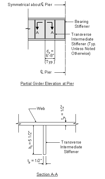
Figure 3-14 Transverse Intermediate Stiffener
The first specification check is for the projecting width of the transverse intermediate stiffener. The width, bt, of each projecting stiffener element must satisfy the following:
S6.10.8.1.2
and

Therefore,
OK
Therefore,
OK
The second specification check is for the moment of inertia of the transverse intermediate stiffener. This requirement is intended to ensure sufficient rigidity. The moment of inertia of any transverse stiffener must satisfy the following:
S6.10.8.1.3


Therefore,
Therefore,

Therefore,
OK
The third specification check is for the area of the transverse intermediate stiffener. This requirement is intended to ensure sufficient area to resist the vertical component of the tension field. The area of any transverse stiffener must satisfy the following:
S6.10.8.1.4
for single plate stiffeners


Therefore,
Therefore, the specification check for area is automatically satisfied.
Therefore, the transverse intermediate stiffeners as shown in Figure 3-13 satisfy all of the required specification checks.
Design Step 3.14 - Design for Flexure - Fatigue and Fracture Limit State - Negative Moment Region
For this design example, the nominal fatigue resistance computations were presented previously for the girder section at the location of maximum positive moment. Detail categories are explained and illustrated in STable 6.6.1.2.3-1 and SFigure 6.6.1.2.3-1.
S6.6.1
In addition to the nominal fatigue resistance computations, fatigue requirements for webs must also be checked. These checks are required to control out-of-plane flexing of the web due to flexure or shear under repeated live loading.
S6.10.6
S6.10.6.1
For this check, the live load flexural stress and shear stress resulting from the fatigue load must be taken as twice that calculated using the fatigue load combination in Table 3-1.
S6.10.6.2
As previously explained, for this design example, the concrete slab is assumed to be fully effective for both positive and negative flexure for fatigue limit states. This is permissible because the provisions of S6.10.3.7 were satisfied in Design Step 2.
S6.6.1.2.1
For flexure, the fatigue requirement for the web is as follows:
S6.10.6.3
If
then
Otherwise

For the fatigue limit state at the pier (the location of maximum negative moment):
S6.10.3.1.4a
(see Figure 3-4)
(see Figure 3-4)
(see Figure 3-4)
C6.10.3.1.4a


Therefore,
Based on the unfactored stress values in Table 3-12:

Therefore,
OK
For shear, the fatigue requirement for the web is as follows:
S6.10.6.4
Based on the unfactored shear values in Table 3-13:


Therefore,
OK
Therefore, the fatigue requirements for webs for both flexure and shear are satisfied.
Design Step 3.15 - Design for Flexure - Service Limit State - Negative Moment Region
The girder must be checked for service limit state control of permanent deflection. This check is intended to prevent objectionable permanent deflections due to expected severe traffic loadings that would impair rideability. Service II Limit State is used for this check.
S6.10.5
This check will not control for composite noncompact sections under the load combinations given in STable 3.4.1-1. Although a web bend buckling check is also required in regions of positive flexure at the service limit state according to the current specification language, it is unlikely that such a check would control in these regions for composite girders without longitudinal stiffeners since Dc is relatively small for such girders in these regions.
C6.10.5.1
The web must satisfy SEquation 6.10.3.2.2-1, using the appropriate value of the depth of the web in compression in the elastic range, Dc.
S6.10.5.1
for which:
for webs without longitudinal stiffeners
The factored Service II flexural stress was previously computed in Table 3-12 as follows:
(see Figure 3-4)
for webs without longitudinal stiffeners

(see Figure 3-4)
OK
In addition, the flange stresses for both steel flanges of composite sections must satisfy the following requirement:
As previously explained, for this design example, the concrete slab is assumed to be fully effective for both positive and negative flexure for service limit states.
The factored Service II flexural stress was previously computed in Table 3-12 as follows:
S6.10.5.1

OK
In addition to the check for service limit state control of permanent deflection, the girder can also be checked for live load deflection. Although this check is optional for a concrete deck on steel girders, it is included in this design example at the location of maximum positive moment.
S2.5.2.6.2
Design Step 3.16 - Design for Flexure - Constructibility Check - Negative Moment Region
The girder must also be checked for flexure during construction. The girder has already been checked in its final condition when it behaves as a composite section. The constructibility must also be checked for the girder prior to the hardening of the concrete deck when the girder behaves as a noncomposite section.
S6.10.3.2.2
The investigation of the constructibility of the girder begins with the the noncompact section compression-flange slenderness check, as follows:
S6.10.4.1.4
(see Figure 3-4)
(see Figure 3-4)
In addition, composite girders, when they are not yet composite, must satisfy the following requirement during construction:
S6.10.3.2.2
for which:
for webs without longitudinal stiffeners
For the noncomposite loads during construction:
(see Figure 3-4)
C6.10.3.1.4a
for webs without longitudinal stiffeners

(see Figure 3-4)
OK
In addition to checking the nominal flexural resistance in the web during construction, the nominal shear resistance in the web must also be checked as follows:
S6.10.3.2.3
S6.5.4.2
OK
Therefore, the design section at the pier satisfies the constructibility specification checks.
Design Step 3.17 - Check Wind Effects on Girder Flanges - Negative Moment Region
As stated in Design Step 3.3, for this design example, the interior girder controls and is being designed.
S6.10.3.5
Wind effects generally do not control a steel girder design, and they are generally considered for the exterior girders only. However, for illustrative purposes, wind effects are presented below for the girder design section at the pier. A bridge height of greater than 30 feet is used in this design step to illustrate the required computations.
C6.10.3.5.2 & C4.6.2.7.1
S3.8.1.1
For noncompact sections, the stresses in the bottom flange are combined as follows:
S6.10.3.5.2
Since the deck provides horizontal diaphragm action and since there is wind bracing in the superstructure, the maximum wind moment on the loaded flange is determined as follows:
C4.6.2.7.1

S1.3
 |
Strength Limit States for Wind on Structure For the strength limit state, wind on the structure is considered for the Strength III and Strength V Limit States. For Strength III, the load factor for wind on structure is 1.40 but live load is not considered. Due to the magnitude of the live load stresses, Strength III will clearly not control for this design example (and for most designs). Therefore, for this design example, the Strength V Limit State will be investigated. |
for Strength V Limit State
STable 3.4.1-1
Assume that the bridge is to be constructed in Pittsburgh, Pennsylvania. The design horizontal wind pressure is computed as follows:
S3.8.1.2
STable 3.8.1.2.1-1

S3.8.1.1

for a bridge located in a city
STable 3.8.1.1-1

assumed wind velocity at 30 feet above low ground or above design water level at bridge site

S3.8.1.1
assumed height of structure at which wind loads are being calculated as measured from low ground or from water level
for a bridge located in a city
STable 3.8.1.1-1
S3.8.1.1

S3.8.1.2.1
After the design horizontal wind pressure has been computed, the factored wind force per unit length applied to the flange is computed as follows:
C4.6.2.7.1
S1.3
for Strength V Limit State
STable 3.4.1-1
from bottom of girder to top of parapet
Next, the maximum lateral moment in the flange due to the factored wind loading is computed as follows:
C4.6.2.7.1
Finally, the flexural stress at the edges of the bottom flange due to factored wind loading is computed as follows:
S6.10.3.5.2
The load factor for live load is 1.35 for the Strength V Limit State. However, it is 1.75 for the Strength I Limit State, which we have already investigated. Therefore, it is clear that wind effects will not control the design of this steel girder. Nevertheless, the following computations are presented simply to demonstrate that wind effects do not control this design:
Therefore: ![]() OK
OK
Therefore, wind effects do not control the design of this steel girder.
Design Step 3.18 - Draw Schematic of Final Steel Girder Design
Since all of the specification checks were satisfied, the trial girder section presented in Design Step 3.2 is acceptable. If any of the specification checks were not satisfied or if the design were found to be overly conservative, then the trial girder section would need to be revised appropriately, and the specification checks would need to be repeated for the new trial girder section.
The following is a schematic of the final steel girder configuration:
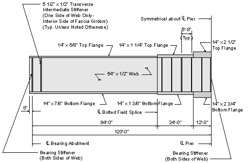
Figure 3-15 Final Plate Girder Elevation
For this design example, only the location of maximum positive moment, the location of maximum negative moment, and the location of maximum shear were investigated. However, the above schematic shows the plate sizes and stiffener spacing throughout the entire length of the girder. Some of the design principles for this design example are presented in "tip boxes."
Design computations for a bolted field splice are presented in Design Step 4. Design computations and principles for shear connectors, bearing stiffeners, welded connections, and cross-frames are presented in Design Step 5. Design computations for an elastomeric bearing pad are presented in Design Step 6.
| << previous | Contents | next >> |


