

| << Previous | Contents | Next >> |
Connection Details for PBES
Chapter 1 - General Topics
1.6 Materials
This section provides an overview of the many different types of materials used in prefabrication and discusses the impact of the materials on accelerated construction processes.
1.6.1 Concrete
Concrete is a popular material for prefabrication and accelerated construction projects. The ability to build elements off site in virtually any shape makes this material a prime choice for designers. Common prefabricated concrete elements include beams and girders, full depth deck slabs, and pier caps. Several states have built entire bridges using precast concrete elements including pier columns, abutment stems, footings, and retaining walls.
Concrete is also used for making connections between different prefabricated bridge elements. These connections often require the use of high early strength concrete to allow for accelerated construction processes.
Durability is a major concern of bridge owners. The new generation of high performance concretes offer durability that far exceeds the performance of past concretes. Plant produced precast concrete also has the advantage of being constructed in a controlled environment with higher production and curing standards than normally found in the field. This benefit of accelerated construction projects is often overlooked by designers.
1.6.2 Structural Steel
Steel elements are well suited for prefabrication and accelerated construction. There is a high degree of control over fabrication tolerances; therefore, complex connections can be employed using structural steel. Common elements include steel beams and girders, steel grid decks (including concrete and grid exodermic decks), and steel railings. Other less common applications include steel pier columns and bents.
One advantage that steel has over precast concrete is that it typically weighs less than an equivalent concrete element. This factor can be critical when shipping and crane capacities limit the amount of room for erection. A disadvantage relative to precast concrete is steel's greater flexibility. More attention is required to ensure deflections and internal stresses of elements and systems are not exceeded during transport.
1.6.3 Timber
Timber bridges were common in the 1800's. There has been a resurgence in the use of timber as a bridge material during the last two decades. The use of glue laminated products and the introduction of composites make the design of larger timber bridge elements more practical and cost effective. Common types of prefabricated timber bridge elements include glue laminated deck panels and glue laminated beams and stringers.
1.6.4 Fiber-Reinforced Polymers (FRP)
There has been much research into the use of fiber-reinforced polymers in recent years. Many states and universities have experimented with these materials. The development of carbon fiber polymers has made the use of FRP materials practical for bridge applications. Types of FRP bridge elements include beams and stringers and full-depth deck panels. The state of New York has had FPR deck systems in place for almost a decade with excellent performance.
1.6.5 Grouts
The majority of precast concrete elements discussed in this Manual are joined with grout. The connections between precast concrete elements require the use of grout to fill the void between the adjoining elements. Nominal width joints are required for several reasons. The primary reasons are to allow for element tolerances and to make adjustments in the field. See Section 1.7 for more information on element tolerances.
Non-shrink cementitious grout is most often used to easily and efficiently provide a durable, structurally stable connection between precast concrete elements. Epoxy grouts can be used; however, they tend to have a low modulus of elasticity and are expensive when compared to cementitious grouts. In order to achieve desired results, careful selection and specification is required when using non-shrink grouts.
1.6.5.1 Grout types
There is no such thing as a generic non-shrink grout. There are several different types of grouts, each with its own advantages and disadvantages. Cementitious non-shrink grouts are inexpensive, generally easy to work with, and develop adequate strengths in reasonable time. These grouts are often pre-packaged and can be extended using small diameter stone for larger pours. Cementitious grouts are ideal for static and light dynamic loadings. This section will focus on cementitious non-shrink grouts since they are adequate for virtually all prefabricated connections. Other grout types may be acceptable for precast connections but require additional specification and suitability considerations on the part of the designer.
Ideally a non-shrink cementitious grout will not exhibit dimensional change in the plastic or hardened state. To achieve non-shrink characteristics in grout, additives are mixed into the grout to counteract the natural tendency of grouts to shrink. There are different types of additives for cementitious grouts in the market. The additives have certain advantages and disadvantages. Several common additives are as follows:
Gas generating:
This is the most common grout type. A chemical substance is added to the grout mixture to control shrinkage. In most cases, an aluminum powder is used. A chemical reaction occurs with the aluminum powder and the alkalis in the cement during the plastic phase to form hydrogen gas. The generated gas is used to promote expansion.
However, because small amounts of aluminum powder are used, the expansion can be difficult to control under various conditions. This uncontrolled expansion can cause bleed water to form at the grout surface that can cause loss of support and bond. This has led to the development of alternative compounds that can ensure a quality grout under varying conditions.
Ettringite:
Ettringite expansive grout relies on the growth of ettringite crystals during the hardened state to counteract shrinkage.
Air release:
Air release grouts do not rely on a chemical reaction to achieve expansion. The additive reacts with water to release air and cause expansion.
1.6.5.2 Environmental Conditions
Each of the additives mentioned above rely on specific conditions to achieve a desired result:
Temperature:
The temperature at the time of placement needs to be carefully controlled for some grouts. In particular, gas generating nonshrink grouts have a small window of acceptable temperatures for achieving the desired expansion. Cold temperatures can inhibit the chemical reaction, thus limiting expansion. Higher temperatures can cause rapid expansion that limits placement time. The typical temperature range for grout placement is between 40 and 90 degrees Fahrenheit. Designers should investigate manufacturer's requirements for grouting in temperatures beyond these typical ranges. For extreme conditions, the area may need to heated or cooled during the curing process.
Moisture:
Water should always be added to non-shrink grout in strict accordance with the manufacturer's specifications. Deviation from specified water content can adversely affect the performance of the grout. Trial batching of grout should always be specified in contract documents.
For example, ettringite crystals grow during the grout's hardened state. If too little water is added or if water is drawn out of the mixture due to a dry surrounding substrate, the expansive growth will be less than desired. Conversely, over-watering can cause segregation, increased shrinkage and reduced strength. Over-watering can cause bleed water to accumulate at the grout surface, leading to loss of support and bond.
Surface preparation:
Additives used in non-shrink grouts rely on moisture to achieve expansion and counteract shrinkage. A dry concrete substrate will draw water out of the grout mixture and cause a weak layer to develop at the grout member interface.
Surface preparation is of particular importance for grouts with low water content, since a small loss of grout moisture can lead to a brittle grout. Concrete surfaces should be wetted to a saturated surface dry (SSD) condition prior to application of grout. SSD conditions are achieved when the base concrete is moist; however, there can be no standing water present.
There are common misconceptions as to how to achieve a SSD condition. Many contractors will simply apply water to the interface just prior to grout placement. Proper SSD conditions usually require pre-soaking the area for a specified time. Each manufacturer has recommended pre-soak times, which should be followed. (Note that epoxy grouts do not require pre-soaking).
1.6.5.3 Placement Methods
Depending on the size and location of the void to be grouted several different techniques are used for placement:
Dry Pack:
Dry pack grouting does not require the use of formwork; however, dry packing is labor intensive and requires highly skilled workers in order to place the grout properly. This method involves using a very dry grout that can be balled up in the hand. Dry packing should only be used for small voids that are easily accessible. The process involves ramming the grout into place with tools (not only by hand). If the space is not confined, there will be no place to pack the grout against, which will result in loose placement and a poor quality joint.
Pouring:
By varying the water content according to the manufacturer's specifications, grout can exhibit a near fluid consistency. Fluid grouts can be poured into voids by gravity feed if there is access to the void from the top. Placing grout by pouring requires the use of forms and a head box to ensure containment and proper placement. The forms should be designed to resist the hydraulic head that will develop in the connection. Foam backer rods have very limited resistance to significant pressure and should only be used for very small vertical pours. Solid forms should be used for most applications.
Pumping:
Typical pumping applications use grouts that exhibit a flowable consistency that is stiffer than fluid consistency. Therefore, less water can be used in the grout which will result in higher compressive strengths. Pumping should be used for large grout installations or areas with accessibility problems. Unlike pouring it does not require the use of a head box. The void that is to be grouted will need to be formed. Grout delivery tubes and air vent tubes are also required to ensure that all voids are filled. Pumping grout into confined pockets needs special attention to quality control. Specifications should require trial pours in mockup joints. These mock-ups can be disassembled and inspected for voids. Adjustments to air vent locations may be required after the mock-up testing.
Post-tensioning Duct Grouting
Many details in this manual involve the use of post-tensioning (PT) systems. Grouting of post-tensioning is a specialized field that required quality products and expertise. Many state DOT's have developed standard PT grouting specifications. Users of this manual are encouraged to contact specific DOT's for more information on approved PT grouting materials and methods. Information can also be obtained at the American Segmental Bridge Institute (ASBI) website (www.asbi-assoc.org) or from posttensioning material manufacturers.
1.6.5.4 Curing
There are several methods for curing cementitious grouts. The most important factor is to follow the manufacturer's specified curing methods. Each particular grout manufacturer may have unique curing characteristics that are required in order to achieve the desired grout properties. The following curing procedures are most common:
Wet Curing:
Wet curing is used to prevent loss of surface water. During wet curing, all exposed surfaces should be covered with continuously wetted burlap for a specified time. Most manufacturers recommend a minimum of three days of wet curing.
Curing Temperature:
For most grouts, the surrounding substrate should be kept at a temperature between 40 and 90 degrees Fahrenheit for a minimum of 24 hours during and after grouting.
Curing compounds:
Curing compounds can be applied to the exposed surface of the grout in place of continuously wet curing. Curing compounds do not replace wet curing, they simply reduce the amount of time required for wet curing. Application of curing compounds can vary by product; and therefore, it is necessary to follow the manufacturer's recommendations for use of curing compounds. Typically, all surfaces should be wet cured for at least one day before the curing compound can be applied to all surfaces. Curing compounds for grouting should meet the requirements of ASTM C 309, Type 2, Class B [8].
1.6.5.5 Specifications
Non-shrink cementitious grouts are sometimes simply specified as "non-shrink grout". However, without specifications to control material properties the resulting product may shrink, resulting in a poor quality connection. Therefore, it is imperative to use ASTM standards when specifying any "non-shrink" grout. The following are a list of standard specifications that should be used when specifying grout.
- ASTM C 1107 - Standard Specification for Packaged Dry, Hydraulic-Cement Grout (nonshrink) [9]
- ASTM C 928 - Standard Specification for Packaged, Dry, Rapid-Hardening Cementitious Materials for Concrete Repair [10]
- CRD C-621 - Army Corp of Engineers Specification for Non-Shrink Grout [11]
These documents specify testing and sampling methods for grouts as well as batching, mixing, and proportioning requirements. Grout compressive strength is measured using two-inch square cubes in place of test cylinders (ASTM C 109 [12]). Shrinkage is measured via a vertical height change method. There are two methods commonly used. ASTM C 827 [13] measures height change in the plastic state. ASTM C 1090 [14] measures height change in the hardened state. These standards also reference specifications for flowability, consistency, and working time. ASTM D6449 [15] is the standard flow cone test for flowability. This test is often the most critical for controlling quality of flowable grouts.
Most state transportation agencies have approved non-shrink grout product lists. During the design process of a prefabricated bridge project, designers should carefully review each state-approved product to see if it is appropriate for the particular connection being used. The grouts that meet the project requirements should be clearly specified. Designers should carefully evaluate any request from contractors to substitute other grout materials.
1.6.5.6 Quality Control
A properly specified grout is the first step necessary to ensure a quality final product. Quality control from the manufacturer to the contractor can be the cornerstone of a job well done. For initial grouting procedures and trial batching, the designer should specify that a manufacturer's representative be on site as the grouting process begins. This can avoid guesswork on the part of the contractor when it comes time to proportioning and placing materials.
Test Pours, Trial Batching and Mock-ups:
For complex void grouting, trial batching, test pours and test mock-ups are recommended. This is especially true for large or irregular shaped pours and pumping operations. The layout and placement of delivery and vent tubes in large pumped grout voids may require testing of several different layouts to achieve a quality product. Wood mock-ups of portions of each element to be joined can be used to test grouting procedures. After curing, the mockup can be dismantled and the grout void inspected. If significant voids are found, the contractor can modify the placement of delivery and vent tubes and repeat the test. It should be noted that this testing procedure should be completed prior to fabricating the precast elements to be joined since the delivery and vent tubes are often embedded in the elements.
Grouting of Post-Tensioning Ducts
Quality control during grouting of post-tensioning ducts is critical to a successful long lasting system. There have been several problems with corrosion and failures of post-tensioning systems in Florida. Improved quality control is thought to be the best approach to eliminating these problems in the future.
The American Segmental Bridge Institute (ASBI) offers a Grouting Certification Program that is intended to provide supervisors and inspectors of grouting operations with the training necessary to understand and successfully implement grouting specifications for post-tensioned structures.
Individuals, who successfully complete the ASBI Grouting Certification Training and have three years of experience in construction of grouted post-tensioned structures, are certified as "ASBI Certified Grouting Technician." Some State DOT's already require this certification for grouting procedures involving posttensioning ducts. States that plan to employ significant posttensioning designs in the future should consider this program. More information on this topic can be found at the ASBI website (www.asbi-assoc.org).
1.7 Tolerances
Tolerances can be the source of most problems in accelerated bridge construction projects. Field fit-up is also one of the major concerns of agencies who are considering an accelerated bridge project using prefabricated elements. Designers of a prefabricated bridge project should assume that nothing is perfect and that tolerance will need to be accounted for in every connection. The following sections discuss the issues with tolerance in prefabricated bridge elements.
1.7.1 Element Tolerances
A common misconception by designers of prefabricated bridge projects is that the elements are built to exact dimensions. In fact, all prefabricated elements are built to some tolerance. The designers should be aware of the specified construction tolerances for cambers, sweep, and overall dimensions in all elements. The locations of holes, inserts and blockouts are also very important.
Prefabrication and accelerated bridge construction projects usually do not need to be designed with elements having stricter tolerances than conventional construction. The tolerances specified by the various industries are usually sufficient. A designer of prefabricated bridges should be familiar with the design tolerances in the states in which each project is located and account for these tolerances in the design and details. Consideration should also be given to whether tolerances used in conventional construction can be increased for prefabricated construction to ease fit-up in the field.
1.7.2 Dimensional Growth
If designers do not account for element tolerances, a phenomenon called "dimensional growth" can occur. For example, if ten panels that are each ten feet wide are placed side by side, the overall length of the system will typically be greater than 100 feet. This is due to the tolerances of the edge of the adjoining pieces. Match casting of concrete projects can minimize this problem, but minor dimensional growth of the structure is inevitable. To address this problem, designers should compensate for member tolerances in the joint designs or allow for minor overall variation in the structure dimensions.
Another form of dimensional growth has to do with the detailing of tolerance limits for multiple protruding elements, post-tensioning ducts, and embedded attachments. It is important to specify that the location tolerance be measured from a common working point. If center-to-center spacing tolerances are used, the layout error tolerance can become additive and affect the connection of the elements.
1.7.3 Hardware Tolerances
The location of hardware in prefabricated elements can be critical to the success of the project. Some hardware elements are more critical than others; therefore, designers need to specify the location tolerances of all hardware and attachments.
1.7.3.1 Post-tensioning Systems
Post-tensioning systems usually require the installation of strand or thread bars after the erection of the individual elements. It is important to specify the tolerance of the location of the ducts, especially at the ends of the element. Match casting is often used to keep these tolerances to a minimum. If small grout keys or closure pours are used, there is a greater likelihood of post-tensioning duct offset at the joints. In this case, it is recommended that ducts be oversized to allow for minor offsets in the duct at the joints.
1.7.3.2 Grouted Reinforcing Splice Couplers
Couplers require a certain degree of tolerance that is attainable in normal precast concrete construction. One method for accounting for tolerances is to oversize the couplers. The typical coupler can accommodate minor variation in bar locations. It is also possible to use an oversized coupler (by two bar sizes) to provide even greater tolerance. This provides approximately ½ inch of tolerance adjustment, which is well within normal tolerances for precast elements.
Precast manufacturers can maintain the level of tolerance between pieces by using frames and jigs as templates to position and support the reinforcing steel and couplers. If a design requires the connection of a precast element to a field cast portion of the bridge, it is recommended that the precast producer provide a template jig to the general contract to ensure proper fit-up in the field during erection. The designer should clearly specify the responsible parties for this approach.
1.7.3.3 Embedded Attachments
The level of tolerance for embedded attachments is a function of the tolerance for the attaching member. If the attachment is for a utility pipe hanger that has adjustability, then the tolerance will not be as strict as it will be for other elements. Designers should clearly identify the required level of tolerance for all embedded attachments.
1.7.4 Layout and Joint Widths
When grouted joints are used between elements, the layout of the structure should be based on nominal element spacing. The actual width of the elements should be equal to the element spacing minus the specified joint width. The width of the joints between the elements should be based on the maximum specified element tolerance, accounting for member sweep, variation in overall dimensions, and variation in the side forms. Typical joint widths range from one-half inch to one-inch depending on the element. Larger elements tend to have larger joint widths.
1.7.5 Closure Pours
Closure pours can allow for large construction tolerances. They are often used to make up for dimensional growth and for unknowns in the field. Even large match-cast structures, such as segmental bridges, use closure pours where large portions of the bridge are joined.
1.7.6 Camber Issues
Camber tolerance is often not given enough forethought by designers in prefabricated bridge projects. Steel and concrete beams have significant camber tolerances. Most designers allow for camber tolerance by requiring a variable web gap or haunch between the top of the beams and the underside of the deck. This is recommended for prefabricated bridge decks as well. Attempting to set prefabricated deck elements directly on top of steel or concrete will result in numerous fit-up problems.
1.7.7 Specification Requirements
In most cases, normal specification tolerances for typical members such as beams and girders are sufficient for prefabricated bridge projects. For specialty elements such as deck slabs and substructure elements, the designer should include tolerance requirements within the specifications or the contract plans. A recommended guide for developing tolerances for elements is the Precast Prestressed Concrete Institute (PCI) Manual entitled "Tolerance Manual for Precast and Prestressed Concrete Construction (MNL 135-00)" [16]. This manual offers recommended tolerances for all types of precast products. Designers are also encouraged to contact local producers to discuss appropriate tolerances.
Another approach is to use a performance type specification that requires the contractor to determine the applicable tolerances for each element and then be responsible for the fit-up in the field. The PCI manual could be used as a reference in the specification.
1.8 Fabrication and Construction Issues
The basis of prefabrication is the construction or fabrication of elements off site or near the construction site. Large-scale prefabrication raises issues not normally encountered on typical bridge projects. Prefabricated elements are large and heavy, requiring special means of fabrication, transport and assembly. This section discusses fabrication and construction issues related to prefabricated bridge projects.
1.8.1 Quality Assurance and Quality Control (QA/QC)
Most transportation agencies have well established QA/QC procedures. Prefabricated bridge projects can encounter different conditions that are not typically encountered on regular bridge projects. For instance, a contractor may choose to make portions of the bridge near the bridge site in a temporary fabrication facility. An agency may have one set of QA/QC procedures for field construction and a separate set of procedures for permanent fabrication plants. A near-site temporary fabrication yard may need special QA/QC procedures that are a combination of procedures for site construction and plant fabrication.
1.8.1.1 Fabricator Certification
There is debate in the industry about certification of fabricators for prefabricated bridge projects. Some states require that all elements be fabricated by producers certified by the Precast/Prestressed Concrete Institute. The positive side to this approach is that the elements will be manufactured by a known source with internal quality controls in place. The negative aspect to this approach is that all the elements will need to be shipped from fabrication plants to the site. This can limit the size of the elements and lead to higher costs. PCI plant certification is recommended for complex elements such as beams and girders. Information on the PCI Plant Certification can be found on the PCI website (www.pci.org).
1.8.1.2 Near Site Fabrication
Several states have allowed near site fabrication. This approach is common in the segmental bridge industry; however, it is not often used for smaller bridges. The cost and time of setting up a certified fabrication facility near the bridge site can be significant. One option may be to allow prefabrication of the less complicated elements in the field. Examples of these elements are footings, abutment and wall stems, and pile caps. Often these elements are the heaviest elements in the prefabricated bridge. If these elements can be fabricated in a location that does not require shipping over roads, the weight of the elements can be increased dramatically. It is not uncommon to move 200-ton segmental bridge sections from a nearsite fabrication yard.
1.8.1.3 Inspection
Inspection of prefabricated bridge elements is critical. In order to ensure the proper fit of prefabricated elements, a higher degree of inspection will be required. Forming of concrete in the field will be replaced by prefabricated pieces that will need to be constructed to a specified tolerance. The success of a prefabricated bridge project will hinge on the level of quality and accuracy of each element.
1.8.2 Handling and Shipping
1.8.2.1 Element Weight and Shipping
There are many factors that can affect the maximum size of an individual element. The following are some of the most common factors:
Over-the-Road Shipping Limits:
Every state has requirements for shipping of oversize and overweight loads that can limit the permissible size of the elements. Because designers do not know where an element will be fabricated, investigation of possible shipping routes is not possible. Designers should become familiar with the shipping requirements of the state where the bridge exists, and any neighboring states, to set reasonable limits on element size and weight.
Designers can often facilitate shipping over the road by identifying any deficient bridges or height and width restrictions on main roads leading to the site. Contractors usually do not have the time or resources to determine exact shipping routes for heavy elements in the short time allotted for bidding. A defined access road to the site from major highways would be beneficial to prospective bidders.
Barge and Rail Access:
Access to the bridge site by rail and water can allow for larger element sizes and weights. Barge access may allow large-scale prefabrication, including the potential for total superstructure prefabrication. Barge access should be identified in the project plans if this option is viable. The necessary permits for the project (environmental, Coast Guard, etc.) should identify barge access points, anchor sites and staging areas.
Near Site Shipping:
If near-site fabrication is an option, the size of individual elements can be increased dramatically. It may be possible to prefabricate an entire multi-span superstructure with substructure.
Crane Capacities:
If lifting of elements is to be done by cranes, the size of the elements may be limited. Large elements will require large cranes that may not fit within the construction site. This is often the case for bridge replacements where maintenance of traffic is required. Also, the cost of large cranes can become prohibitive.
Lifting Hardware:
Normal lifting procedure for individual elements is a four-point sling. This involves four cables attached to four discrete points on the piece. Typically, erection engineers assume that only two of the points are supporting the load at any time. The capacities of lifting hardware are sometimes limited, especially if the element being moved is a thin concrete panel. It is possible to use more complex lifting arrangements. Designers should consult with erection contractors for lifting of very large or heavy elements.
Use of Self-Propelled Modular Transporters (SPMTs):
In the U.S., entire superstructure spans have been lifted, carried, and placed in final position with SPMTs. In Europe, SPMTs have been used to install multi-span superstructures complete with substructures, with weights up to 3600 tons moved from near-site staging areas.
Member Stresses During Lifting
Often precast elements are lifted from point that different than the final support points. This can have a significant affect on the component. This is especially true for pretensioned members that are highly prestressed. Lifting a pretensioned beam far from the beam end can easily overstress the beam and lead to cracking and even failures. Non-prestressed concrete members can also experience cracking during handling. Designers of precast concrete components should investigate handling stresses.
It may be desirable to incorporate minor amounts of prestressing in components that are designed with mild reinforcement in order to minimize the potential for cracking during handling. It should be noted that this approach will most likely increase the cost of the component since it may need to be cast in a prestressing bed.
1.8.2.2 Recommended Design Approaches to Element Weight
Virtually all items listed in Section 1.8.2.1 are unknown to the designer of a prefabricated bridge project. This makes the layout and size of elements difficult, and it raises the possibility of claims from contractors if they find that they cannot ship the elements.
One approach that has been used by the New Hampshire DOT is to detail a schematic layout of the bridge and its elements on the plans and to allow the contractor to determine the number of segments in an element, for example, the number of segments in an abutment backwall, as part of a detailed assembly plan that is submitted to the engineer for approval. The designer notes certain limits on joint locations, but leaves the maximum segment size and weight and the exact location of all joints up to the contractor.
Another approach is to simply detail the bridge as a cast-in-place bridge, and show details for typical prefabricated connections. The contractor can then develop an assembly plan based on the geometry of the bridge and the details provided.
By using these methods, element size and weight can be set by the contractor to provide the most cost effective bridge, taking into account all the factors that the designers simply do not have during the design phase of a project.
1.8.2.3 Imperfections, Damage and Repairs
The process of fabricating, shipping and handling of elements can lead to damage and subsequent repairs. The Precast Prestressed Concrete Institute has recently published a document entitled "Manual for the Evaluation and Repair of Precast, Prestressed Concrete Bridge Products (MNL-37-06)" [17]. This document includes information on imperfections and damage that occur from fabrication through erection of precast concrete products. The manual is written for typical bridge products such as girders and beams. Designers may want to establish similar criteria for other prefabricated bridge elements.
Steel elements tend to be easier to handle and ship without damage than precast concrete elements. If damage occurs to a prefabricated steel element, there are well established procedures for repair outlined in typical project specifications, as described in the ANSI/AASHTO/AWS Bridge Welding Code [18].
1.8.3 Constructability
Constructability can be a major factor in the development of a prefabricated bridge plan. This is especially true for projects within tight confines. Contractors are often required to work in limited space and time constraints. Existing and future FHWA manuals will address these issues in detail. The following sections are presented as an overview on constructability.
1.8.3.1 Cranes
Crane capacities and crane footprints can have a major impact on the constructability of a prefabricated bridge. Designers should attempt to provide as much room as possible for crane setting locations. Designers should also provide enough time for crane set-up and breakdown if the cranes are to be placed in travel ways.
1.8.3.2 Self-Propelled Modular Transporters (SPMTs)
A new generation of heavy lifting equipment has been developed by the shipping and petrochemical industries. The piece of equipment that provides the most flexibility and speed is the Self-Propelled Modular Transporter. SPMTs can lift very large loads and move them in multiple directions with a high degree of accuracy. The following photo shows the new Providence River Bridge in Providence, Rhode Island. SPMTs were used to move this six-million-pound bridge from a shipping pier onto two large shipping barges where it was then shipped to the project site. The prefabrication of this superstructure and the use of SPMT's saved the contractor approximately one year in construction time.
Figure 1.8.3.2-1 Providence River Bridge
(Photo Courtesy of Mammoet)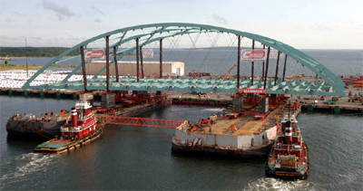
The FHWA has published a detailed manual on the use of SPMTs [3]. Designers are encouraged to review this manual to learn more about the use of SPMTs.
1.8.3.3 Temporary Support of Elements
In a typical prefabricated bridge project, portions of the bridge may need to be supported on temporary falsework until the bridge is whole. Designers should account for the space needed to install temporary supports, as well as the time required for assembly and disassembly. In some cases, the structure will be supported in a configuration that is quite different from the finished product. Figure 1.8.3.2-1 shows a steel arch being temporarily supported at the third points, which had a dramatic effect on the internal stresses in the structure. Temporary framing (vertical struts) needed to be designed in order to keep the stresses within tolerable limits. Any structure that is to be placed on temporary supports needs to be checked for these temporary stresses. If the lifting method is shown on the contract drawings, then the designer should verify the feasibility of the lifting method. If the method is proposed by the contractor, the stresses should be checked by the contractor's engineer.
1.8.3.4 Time Constraints
Each prefabricated bridge project will have different time constraints. Section 1.2.3 outlines some typical approaches to accelerated bridge construction projects. The time constraints will affect the feasibility of various methods of prefabrication. The designers need to develop a structure type and prefabrication approach that can be executed within the time constraints of the project site.
Connections play a critical role in this approach. Often the time to develop a structural connection is a function of cure times for grouted connections, and the time to make a welded or bolted steel connection. The development of a connection can be the critical path in a short duration construction project. Designers should contact manufacturers to determine reasonable construction times for each connection.
1.8.3.5 Assembly Plans
It is common for designers to require the submission of erection plans for conventional construction projects. This is normally limited to the erection of beams and girders. Bridges built with prefabricated elements require special erection and assembly procedures due to larger number of elements that need to be erected. The New Hampshire Department of Transportation required the contractor to submit an assembly plan for their first fully prefabricated bridge project. The assembly plan is similar to an erection plan; however, it also includes information such as grouting and grout curing procedures, timing and sequence of construction, and temporary shoring of substructure elements during each phase of construction. It is recommended that projects built with prefabricated elements contain specifications requiring the submission of a detailed assembly plan.
| << Previous | Contents | Next >> |