

| << Previous | Contents | Next >> |
Connection Details for PBES
Chapter 2 - Superstructure Connections
This chapter is devoted to connections in superstructure systems. Superstructures are defined by AASHTO as "Structural parts of the bridge that provide the horizontal span." This is a very general definition. For conventional bridges, the superstructure is often defined as the portion of the bridge above the bridge bearings.
Integral abutments and integral piers are special bridge elements that are not clearly identified by the AASHTO definition. An integral abutment connection is a connection between the superstructure and the substructure. For the purpose of organizing this Manual, the integral connection between the superstructure and the substructure has been categorized as a superstructure connection, and is included in this chapter.
The following sections discuss typical systems of superstructure connections used on most bridges. These systems include decks, stringers/beams, and large modular systems.
2.1 Deck Systems
Because prefabricated decks are typically designed and constructed as complete systems, this section is divided into common types of systems, rather than individual connection types. Deck systems are the most commonly used for accelerated bridge construction projects, due to several distinct advantages. First, the conventional construction of a concrete deck (concrete is the most common material for decks), can be very time consuming because of the significant amount of forming required to cast the deck. Prefabrication can minimize or eliminate the need for field forming of concrete. Second, the elements are smaller and easier to transport and place than are most other bridge elements.
Most bridges are parallel stringer structures where the beams run parallel to the roadway centerline. In these bridges, the deck is analyzed and designed as a oneway slab with the strength design being in the transverse direction. In a concrete deck, the primary strength bars run perpendicular to the bridge beam. The reinforcement that runs parallel to the beams is used for distribution of strength. Some structures, such as trusses and girder/floorbeam bridges, have the support framing running perpendicular to the roadway centerline. In this case, the strength direction is in the longitudinal direction.
The design of connections between prefabricated deck elements is largely a function of whether the connection will be used to transfer moments and shears caused by wheel loads (transverse reinforcement between supporting members) or to assist with distribution (typical reinforcement parallel to supporting members). Most systems presented in this Manual can be used in either direction; therefore, the description of the connections will be as follows:
Strength Direction:
This is a connection used to resist forces (moments and shears) based on the strength design of the deck element. For example: On a typical stringer bridge with a concrete deck, the strength direction forces are resisted by the transverse reinforcing steel in the deck.
Distribution Direction:
This is a connection used to distribute forces laterally between elements. For example: On a typical stringer bridge with a concrete deck, the distribution direction forces are resisted by the longitudinal reinforcing steel in the deck.
2.1.1 Full-Depth Precast Concrete Deck Slabs
Full-depth precast concrete deck systems have been used by a number of states. A group of northeast states, working as a PCI Bridge Technical committee, has published design and detailing standards for this type of system. In general, this system is designed as a one-way slab between supporting beams using either mild reinforcement or prestressing.
There has been significant research [19-36] in this area; therefore, many of the details are thoroughly tested and the behavior of the systems is well known. Most research has focused on the connection between the deck and the supporting beams. Composite action is a prerequisite for most designers; therefore, this connection is critical. Most of this research has been completed on steel beam connections, and several studies have been completed on precast concrete beams. More research is underway on the connection of deck slabs to concrete beams; therefore designer should keep apprised of further work in this area.
A number of bridges built with full-depth precast concrete decks have been in service for more than 10 years, and the performance has been excellent. One notable bridge is the Woodrow Wilson Bridge that crosses the Potomac River near Washington, D.C. This bridge carries Interstate 95 and is one of the most heavily traveled bridges in the country. In the 1980's, the deck was replaced with full-depth precast lightweight concrete slabs [37]. The Maryland DOT has noted that the deck had performed very well under the most severe environment until it was replaced by the new Outer Loop Bridge in the summer of 2006. Several bridges in Connecticut were re-decked in the early 1990's using this system. These bridges have been in service for over 10 years and are in excellent condition.
The following sections contain information on the typical connections used in full-depth precast concrete deck slab systems.
2.1.1.1 Connections Between Slab Elements
There are two distinct types of element connections used between adjacent slab elements; one in the strength direction and one in the distribution direction:
Strength Direction:
This connection is used to tr ansfer primary deck moment and shear from one deck element to another. The most common applications of the connection are to make connections between construction stages, and to provide a cross slope change in the deck. This is often done by placing a small cast-in-place closure pour between the adjacent panels.
Experience has shown that the need to provide a small reinforced closure pours does not preclude the use of precast deck slabs for accelerated construction projects. High early strength concrete can be used to make this connection and the bridge can often be opened to traffic in less than one day.
Distribution Direction
This connection is primarily used to transfer shear and minor distribution moments between adjacent panels. The most common form of this connection is a grouted shear key with longitudinal post-tensioning placed across the key to insure that the joint remains in compression under the worst loading condition, which normally is a live load negative moment area. Several agencies have experimented with joints without posttensioning; however, leakage through these joints has been noted.
There is on-going research into improving this connection and possibly developing a connection that does not require posttensioning [22]. Post-tensioning is a slow and costly process. Elimination of post-tensioning would further accelerate the construction of a precast concrete deck slab system. Users of this Manual should keep apprised of the results of this research.
Connection Design Considerations
The strength direction connection needs to be designed to transfer the full moments and shears in the deck slab. This is important for the performance of the deck as well as the performance of the bridge framing below.
The design requirements for the distribution direction connection are not as well defined. Some designers believe that the connection only needs to transfer shear; however, many designers understand that this connection also needs to resist some bending moment caused by the localized effects of a wheel load. This is the reason that post-tensioning designs are used by many agencies.
Some guidance on these connections is available in the AASHTO LRFD specifications. Section 9.7.5 [1] recommends that longitudinal post-tensioning be used at mid-depth of the deck, and that the effective prestress force not be less than 250 pounds per square inch (psi). It should be noted that 250 psi is a net effective value used on several successful designs. However, if a bridge is continuous, designers should consider increasing the posttensioning stress over piers to overcome any tension in the deck caused by composite dead loads. Some designers also increase the post-tensioning to account for live load tension stresses in the deck.
2.1.1.2 Connections to Steel Beam Framing
The connection of precast concrete full-depth panels to steel beams usually consists of a rectangular or oval pocket above the beam that allows the installation of welded stud shear connectors after the panels are set. Some designers prefer the oval shaped pocket to minimize the potential for cracking in the precast panels emanating from the corners of the pocket. The oval pockets are more expensive to fabricate, but the additional cost is usually insignificant.
Once filled with grout, the pocket has proven to develop full composite action. Often the pockets are tapered in the vertical direction to provide more of a mechanical connection between the grout and the panel.
The design of the composite action using this system is the same as conventional shear connector design, except the spacing of the studs needs to match the spacing of the pockets. The variation in shear strength required is accounted for by varying the number of studs in the pockets. The maximum spacing of the pockets is 2 feet on center, based on requirements of Article 6.10.10.1.2 of the AASHTO Specifications [1]. This section states:
The center-to-center pitch of shear connectors shall not exceed 24.0 in. and shall not be less than six stud diameters.
This provision has been in the AASHTO Bridge Design Specification for many years, though its source is not well known. Current research [22] has shown that the maximum spacing of shear connectors may be increased. Typically, increasing the spacing also requires increasing the size of the shear connectors. Users of this Manual should keep apprised of any changes to the AASHTO Design Specification that may result from this research.
2.1.1.3 Connections to Concrete Beam Framing
Most full-depth precast concrete deck systems have been installed on steel framing. As stated in the previous section, the connection to steel framing has been well researched and verified. The connection to concrete beams is not as thoroughly researched, but several universities have recently researched this connection [32-33]. The approach is to use a system similar to the steel framing connection. Hooked reinforcing steel and welded stud shear connectors projecting from the beam have been studied. For systems with headed studs, two options have been studied. One option is to embed a steel plate in the beam and field weld studs in a manner similar to a steel girder connection. There are concerns that this welding might result in cracking of the surrounding concrete due to thermal effects. This concern has not manifested itself in laboratory testing and in the field on several projects. It is recommended that the thickness of the embedded plate be kept thick in order to better disperse the heat from the weld. Another option is to embed a headed stud directly into the beam. The difficulty in these systems is the location of embedded bars or studs. The layout of these bars needs to be carefully planned during fabrication of the beams so that the studs will line up with the blockouts in the precast slab above.
Another option for connecting to concrete beams is to drill and grout the connectors in the field after erection and placement of the deck panels. Drilling into the top of a prestressed beam will not be a problem in most cases because the prestressing steel is usually located near the bottom of the beam.
Recent research at Virginia Polytechnic Institute & State University [33] indicates that the provisions in the AASHTO Specifications for Interface Shear Resistance are adequate for the design of projecting reinforcing steel grouted in a pocket in a precast deck slab. The provisions for interfaces not intentionally roughened most closely matched the research data. This research also confirmed the validity of a connection with welded stud shear connectors attached to an embedded plate. In this case the AASHTO provisions for design of welded stud shear connector was validated. Specific provisions for the design of these connections will likely be published in the AASHTO Design Specifications in the near future.
2.1.1.4 Connections of Parapets, Curbs, and Railings
The connection of a parapet, curb or railing to a precast concrete fulldepth deck panel needs to satisfy all the criteria for a nonprefabricated system. FHWA requires that all parapets and railings on the National Highway System (NHS) be crash tested. This requirement has limited the number of prefabricated parapet and railing connections. States may use parapets and railings designed according to the AASHTO Specifications [1] for non-NHS projects.
Some states anchor prefabricated barriers to full depth slabs by through bolting the barrier or railing to the deck. In this scenario, the bolt projects down below the deck and is secured with a nut and an anchor plate. This type of connection has been problematic. If the bolts are placed in pre-formed holes, water can migrate through the hole and corrode the anchor plate and the underlying framing. If this connection is used, it should be properly sealed.
The AASHTO LRFD Bridge Design Specifications [1] require that all barriers and railing be crash tested in accordance with the requirements outlined in NCHRP Report 350 entitled "Recommended Procedure for the Safety Performance Evaluation of Highway Features" [47]. This document is published by the Transportation Research Board and is available for download at the Transportation Research Board online publication website. There is at least one proprietary precast concrete barrier that has been approved for use. ClampcreteTM is a system that uses polyester resin anchors that are drilled into the bridge deck. This barrier is approved for use on the federal highway system. Figure 2.1.1.4-1 shows the features of the Clampcrete™ system.
Figure 2.1.1.4-1 Clampcrete™ Barrier System
Detail Courtesy of Clampcrete™
The New York DOT has developed a static load procedure for parapets based on the LRFD Bridge Design Specifications [1]. This procedure is useful for testing of parapet sections that have shapes similar to standard parapets. The test verifies the structural integrity of the parapet, but not the vehicle impact performance. The theory is that the reaction of the vehicle to the barrier is a function of the shape, assuming that the barrier has close to zero deflection during impact. If a precast parapet has a shape similar to a crash tested shape, then only the structural integrity of that parapet needs to be evaluated. Note that this is a New York State DOT requirement, which may not be acceptable in other states.
The following methods have been used for this connection:
Concrete Parapets and Curbs
Most states do not have crash-tested precast parapets; therefore a cast-in-place parapet may be the only option. However, this does not eliminate the potential use of full-depth precast concrete deck systems for accelerated construction projects. In Connecticut, the construction of the parapet was expedited by eliminating construction joints in standard concrete parapets, allowing a full length single pour for the parapet on each span. Using this system, the parapet was installed at a rate of 250 linear feet per day. Some shrinkage cracking was noted; however, these cracks were easily sealed and had no effect on the structural integrity of the parapet.
Another option used to open the bridge to traffic as soon as possible is to place a temporary barrier in front of the proposed barrier. Once the temporary barrier is secured, the construction of the permanent parapet can proceed behind the temporary barrier during off-peak hours.
Several states do have crash tested railings. Texas DOT has several that have been tested to AASHTO Test Level 4. There are also several proprietary parapet and railing systems that have been successfully tested. Designers should refer to state DOT standards for barriers and railings that are acceptable for use on each project.
New Hampshire DOT and the Vermont AOT are developing a precast open railing system. This system has a bolt down connection that can be made quickly. The system has been static load tested in the laboratory and installed on one bridge. Details of this system should be available shortly from the Northeast PCI Bridge Technical Committee Website (www.pcine.org).
Steel and Aluminum Railings
Prefabricated steel railings can be installed on a precast deck system. The anchor bolts can either be precast into the decks or drilled and grouted in the field. Some states drill the anchor bolts completely through the deck and secure them with an anchor plate and bolts. This method can lead to difficulties with alignment of the bolts. There have also been long term maintenance issues with through bolts because they often provide an avenue for leakage of water through the deck. Usually steel railings are placed on top of concrete curbs to control storm water runoff; therefore, the discussion of casting concrete parapets and curbs in the previous section also applies to the design of steel railings.
Some states have standard aluminum rail systems that are bolted to concrete curbs. If these systems are use, designers should be aware that a galvanic reaction will develop between the aluminum and the base concrete. To avoid this, designers simply need to place a thin (1/8" thick is common) elastomeric sheet under the post base plate. This will disrupt the potential reaction. Type 304 Stainless steel anchor bolts should also be used for the same reason. Aluminum railings have had a very good track record of durability as long as these two features are incorporated into the design.
2.1.2 Open Grid Decks
Open grid decks have been used for many years. They are most common on bridges that require lightweight decks, such as moveable bridges and suspension bridges. However, long term durability of elements below the open grid decks are a concern and should be addressed accordingly.
Grid decks are essentially mini-steel framing systems. They usually consist of main rail members in the strength direction that span between supporting beams, and transverse cross bars in the distribution direction that run parallel to the supporting beams.
This Manual includes some typical details from past projects. Users of the Manual are encouraged to contact the Bridge Grid Flooring Manufacturers Association for assistance with connections for specific bridge projects (www.bgfma.org).
2.1.2.1 Connections Between Grids
Since these systems are steel framed members, the connection between grids is usually made with a bolted or welded connection. Bolted connections are preferred to minimize the use of fatigue prone welded details.
2.1.2.2 Connections to Steel Framing
There are several options for connecting grids to steel framing. These include welded, bolted or grouted shear connector pockets. Typically the main bearing bars are connected to the supporting framing.
2.1.2.3 Connections of Parapets, Curbs, and Railings
No details of this type were submitted for publication in this Manual; however, in most cases, steel railings are used due to their light weight. Railings are typically connected to the grids using bolted connections.
2.1.3 Concrete/Steel Hybrid Decks
These systems consist of decks that include a combination of concrete and steel components. The most common systems involve the use of steel grid. There are two common options for these systems, as described below:
Partially Filled Grid Decks
These systems include a steel grid deck in which the upper portion of the deck is filled with concrete after placement. In most cases, the concrete is filled over the top of the grid to improve performance.
Exodermic Decks™
An exodermic deck is a proprietary deck system that is similar to partially filled grid decks except the concrete is primarily placed above the grid. The main bars act as mini-composite steel beams in concert with the concrete over pour. These decks are lightweight and lend themselves to precast operations. The connections used for exodermic bridge decks are similar to precast full-depth concrete deck systems. Figure 2.1.3-1 shows exodermic deck details and Figure 2.1.3-2 is a photograph of an exodermic deck installation during a nighttime closure.
Figure 2.1.3-1 Exodermic Deck Details
Courtesy of the D.S. Brown Company
Figure 2.1.3-2 Exodermic Deck Installation
Photo courtesy of the D.S. Brown Company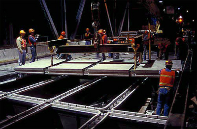
Similar systems include the Effideck™ system developed by the Fort Miller Company in New York. Some details provided by the New York State DOT for this Manual are of the Effideck™ system. This Manual includes some typical details from past projects. Users of the Manual are encouraged to contact the manufacturers of these systems for guidance with connections for specific bridge projects.
2.1.3.1 Connections Between Panels
As with open grid systems, concrete/steel hybrid deck systems are made with steel framed members. The connection between panels can be made with bolts or welds. Bolted connections are preferred to minimize the use of fatigue prone welded details. Grouted keys are also used.
2.1.3.2 Connections to Steel Framing
Since the finished product of concrete/steel hybrid systems is similar to a full-depth precast concrete deck, the connection details are also similar. The connection is usually made with welded stud shear connectors placed in a pocket filled with grout.
2.1.3.3 Connections of Parapets, Curbs, and Railings
In concrete/steel hybrid systems, connections of parapets, curbs and railings are similar to those used in precast full-depth deck panels. Refer to Section 2.1.1.4 for specific information on these connections.
2.1.4 Fiber Reinforced Polymer (FRP) Decks
Fiber reinforced polymers have been used in the aerospace industry for years but have been used only recently in the bridge industry. FPR composites can be manufactured with several different types of fibers combined with polymer resins to form structural shapes. The choice of fiber affects the material properties of the finished product. The most common fibers used are glass fiber and carbon fiber. FRP can be molded into virtually any shape by using established manufacturing methods such as pultrusion and vacuum assisted resin transfer.
FRP products offer the following advantages over other structural materials:
- High strength
- Lightweight
- High Stiffness to weight ratio
- Corrosion resistance
- High quality
These properties have led to the use of FRP decks on load restricted structures. The use of FRP deck panels can have a significant effect on the load capacity of the bridge. To date, most FRP bridge projects have focused on decks. The relatively low modulus of elasticity of FRP products limits their use for elements such as beams and girders. This is not an issue with decks, since the structural spans of the elements are very short. FRP can be molded into cellular panels that can be used as full-depth deck panels. FRP products to date have not been standardized. Each project has been "one of a kind," based on the manufacturing process of the supplier.
FRP deck projects are not limited to the details included in this manual. Virginia has installed three FRP decks. West Virginia, Pennsylvania, and Delaware have also installed FRP decks. Ohio had an initiative to install an FRP deck in each of its counties.
2.1.4.1 Connections Between Panels
The process of making FRP panels allows for development of complex shapes and joint configurations. Interlocking panels and male-female shear keys have been used. High quality epoxy adhesives are used to join panels together.
2.1.4.2 Connections to Steel Framing
FRP panels can be made composite with the bridge framing. Typically pockets are formed over the beams to allow for the installation of welded stud shear connectors and non-shrink grout. Bolts have also been used to connect the panels to the framing.
2.1.4.3 Connections of Parapets, Curbs, and Railings
The connection of parapets and railings to FRP panels is not well studied or documented. On several FRP bridge deck projects, the railing was not attached to the panels. Instead, the railings were attached directly to the steel framing below, or to the truss chords adjacent to the panels.
New York DOT used an FRP railing that was attached to the FRP panels using grouted reinforcing bars. The bars were grouted into voids in the deck panels. The barrier was a hollow FRP box used to form a reinforced concrete parapet. This project was the Route 248 Bridge over Bennett's Creek. Details of this connection are included in this manual.
2.1.5 Partial-Depth Precast Concrete Deck Panels
Partial-depth precast concrete deck panels have been used by many states; for example, 85 percent of all bridges built in Texas use this forming method [38]. These panels are typically 3.5 to 4 inches thick and placed on top of the beams on interior bays. The typical details used in Texas can be found at the Texas DOT Website (www.state.tx.us). Overhangs on bridges with these panels are usually formed using conventional forming methods. The panels have not been cantilevered over the fascia beam because normally the design requires a composite connection between the beam and the deck. A continuous deck panel interferes with this connection. In the past the Texas DOT experimented with a system that used blockouts for shear connectors, but has since decided that it is easier to simply form the overhangs using conventional deck forming techniques.
Once placed, a top layer of conventional reinforcing is placed over the panels and a partial-depth concrete pour is made to finish the composite deck.These deck panels serve two purposes:
- They act as a form to support the wet concrete of the deck pour. The slowest portion of reinforced concrete deck construction is the installation of deck formwork. On a conventional bridge, this is accomplished using wood forms or steel stay-in-place forms. These forms need to be fit between the beam flanges within tight tolerances. The precast concrete panels span between the beams and are supported temporarily on bedding strips on top of the flanges until the deck concrete flows underneath them to provide continuous support; therefore, installation is faster and requires less manufacturing tolerance.
- The deck panels also act as the lower portion of the reinforced concrete deck. This is possible because the moment demand in a deck is primarily positive bending in the middle portion of the bay between beams, and negative bending over the beams. Having a discontinuity over the beams between the panels is not an issue because the moment demand is resisted by the top reinforcing in the cast-in-place top pour.
Research has been completed on partial-depth deck panels. The Texas DOT has sponsored much of this research [39]. There have been laboratory studies and field verification. Strength tests and cyclic live load tests have also been completed. The results of this research show the following:
- Decks composed of precast panels topped with cast-in-place concrete are stronger and stiffer than full-depth cast-in-place concrete decks [40].
- The panels can be considered a part of the structural deck system.
- Composite action between the panels and the topping concrete is possible without the use of horizontal shear reinforcement.
- The panels combined with the concrete topping can be used as a composite deck for the design of the beam.
- It is preferred to use prestressing as the main reinforcement in the panels.
- The amount of force and the size of the prestress strand should be kept as low as possible to minimize cracking and the development requirements of the strand.
Texas and Tennessee have had good performance on their decks where partial-depth precast concrete decks panels have been used. The key to good performance is a positive support between the panels and the top of the girders. Other States have experience problems with the panels where fiber board was used to support the panels and which deteriorated over time or where there was not a positive support between the panels and the girders. Flexibility of the superstructures should also be taken into consideration. Virginia has experienced significant reflective cracks on flexible steel structures with span lengths greater than 140 feet. These reflective cracks can affect the long term durability of the deck, particularly where deicing chemicals are used.
2.1.5.1 Connection to Steel Beam Framing
The connection between partial-depth precast concrete deck panels and steel beam framing is made using welded stud shear connectors in the gap between adjacent panels. This area is filled with concrete as the deck topping concrete is placed.
There is one key feature of this connection that most states strictly adhere to; the deck panel should have concrete bedding placed between the underside of the deck panel edge and the beam below to provide continuous support for the panels to resist live loads. Earlier installations did not use this concrete bedding and excessive cracking occurred above this connection.
Some states require that the prestressing strand in the panels be extended into the area over the beams. This was done to improve the connection of the panel to the beam. Research has shown that these extensions have no affect on the structural integrity of the connection; therefore, many states allow a smooth edge on the panel [40]. This greatly simplifies the production of these panels and has led to reduced costs.
Grade control is often accomplished by stacking shims under the panels. The shim heights are predetermined following a beam grade survey. Several states use leveling screws embedded in the panel that can be adjusted after installation. These screws are temporary and are removed after grout is placed between the panel and the beams.
2.1.5.2 Connections to Concrete Beam Framing
This connection is almost identical to the steel beam framing connection discussed in Section 2.1.5.1. The only difference is that the composite action is made with standard shear reinforcement extending from the beam into the deck. The same issues noted in Section 2.1.5.1 are applicable to this connection.
2.1.5.3 Joints Between Panels
The partial-depth precast concrete deck panels are usually prestressed in the strength direction. The joint between the panels over the beams is essentially a compression connection since it is in the compression zone of the negative moment section of the deck. The cast-in-place concrete simply transfers compression forces between adjacent panels.
The joints in the distribution direction are simply butted in the field with slight gaps. The connection between the panels is made via the concrete topping and topping reinforcing. Even with these small gaps between panels, full composite beam action of the entire bridge deck (precast plus topping) is achieved.
2.1.6 Timber Deck Panels
The United States Department of Agriculture Forest Products Laboratory (USDA FPL) has developed standard details for timber bridges, including details for prefabricated timber panels and beams. There is a significant amount of information on timber bridges at the USDA FPL website. At this time, most timber bridges are used on low volume roadways, but may be applicable to higher volume roads as well. Users of this Manual are encouraged to visit the Forest Products Laboratory website for more information on timber bridges (www.fpl.fs.fed.us).
Prefabricated timber beams and panels are normally manufactured using the glue laminating process. This involves gluing nominal dimension lumber side-by-side to create a solid panel. For beams, the wide dimension of the laminations is normally placed horizontal. For deck panels, the wide dimension of the laminations is typically placed vertical. Protection against rotting is controlled by the use of pressure treated wood products. The individual laminations can be pressure treated before being laminated together, or the laminated pieces can be pressure treated after fabrication. The glue used for bridge application must be water proof.
Timber deck panels have be used in two ways:
- Installed on top of glue laminated wood beams
- Installed on top of steel stringers
- Installed as adjacent-deck-slab superstructure for short span bridges
The following sections contain information on the first two uses. The third use is discussed in Section 2.2.4.
2.1.6.1 Connection Between Panels
The connection between wood deck panels is used to transfer shear between the panels. Earlier versions of this system used only steel dowels placed mid-depth between the panels. This system proved to be problematic for higher volume roadways, especially when a bituminous wearing surface was employed. The connections would eventually loosen, leading to cracking of the pavement and leakage through the joints.
The current details include a load transfer beam placed at mid-bay between the support stringers. This beam provides a more significant shear transfer mechanism. Even with this connection, reflective cracking can occur in the overlay pavement. For this reason, it is recommended that a layer of geotextile fabric be installed between the pavement and the panels.
2.1.6.2 Connections to Framing
The currently used connections of timber deck panels to beam framing are not intended to provide composite action between the beams and the deck, but rather, simply to keep the deck in place over the beams. The system consists of bolts and brackets that connect the deck panels to the beams.
2.1.6.3 Connections of Parapets, Curbs and Railings
The UDSA FPL has developed crash tested parapet details for some timber bridges. The most common details are for stress laminated timber deck bridges. These details have been crash tested for AASHTO Test Level 2 and 4 and are available at the USDA FPL website. Two Railing Details have also been developed for glue laminated timber deck systems that meet the requirements of AASHTO Test Level 2. Users of this Manual are encouraged to contact the USDA FPL for guidance on these connections.
2.1.7 Grouting Techniques for Deck Systems
Many of the systems described in this chapter make use of grout for the connections. Section 1.6.5 in this Manual contains information on grout materials and placement. There are four major uses of grouts in deck systems, as described below.
2.1.7.1 Joint Grouting
Most joints between panels contain a grouted shear key. It is very important that the grout placed in these keys completely fills the void. The most common form of keyway failure is due to inadequate filling of the keys. If voids are present, the mechanical interlock of the key is lost. Project specifications should require the use of flowable grouts. Another method of placement that has proven successful requires minor rodding of the grout after placement.
2.1.7.2 Shear Connector Pocket Grouting
These grout areas are used to make the deck composite with the beam framing. In most cases, the pockets are exposed on the top of the deck; therefore placement of the grout is a simple process.
There is on-going research (not yet published) at the Virginia Polytechnic Institute & State University that has looked into the issues with grouting of shear connector pockets. They have found that certain grouts can shrink slightly; thereby creating minor shrinkage cracks around the perimeter of the pocket. The cracking was not found to be detrimental to the structural capacity of the connection, but water leakage was a concern. These cracks can be easily sealed with methacralate crack sealers. In lieu of this, Most states that use this system overlay the deck with either a bituminous wearing surface combined with a waterproofing membrane, or a thin concrete overlay. Other states have tried thin polymer overlays. Use of overlays will eliminate the need to seal these cracks. The overlay also dramatically improves the riding surface quality of the deck.
A new blind pocket system was recently developed as part of and NCHRP research project. The grout for these blind pockets needs to be pumped through small ports in the top of the deck [22]. This process is similar to grouting post-tensioning ducts.
2.1.7.3 Post-Tensioning Duct Grouting
Many states have standard specifications for this process. It is critical that whichever specification is followed, the specifications are followed precisely in the field. The grout is used to provide corrosion protection to the post-tensioning system and to provide a bond between the strand and the surrounding concrete. Elimination of voids and bleed water are two important issues that need to be addressed with any specification or construction process. Normally grouting starts at the low end of the deck and bleed water ports are placed at the high end of the deck. See Section 1.6.5.6 for more information on grouting of post-tensioning ducts.
The connection of the ducts between panels is typically done using a simple duct splice with duct tape. Some states have used heat shrink wraps as well; however this may not be possible with polyethylene ducts, and it may be difficult to get the heat all the way around the duct in the limited pocket areas.
2.1.7.4 Bedding Under Deck Panels
Typically a gap is used between the underside of concrete bridge decks and the top of the supporting beams to account for tolerances such as beam camber. This gap needs to be filled with grout so that the panels have continuous support for wheel loads. In order to properly fill these thin gaps, a flowable grout will likely be needed. Some states have specified dry pack grouting in this area. This can be done, but it is very labor intensive. It is recommended that dry pack grouting only be used for repair to voids in poured areas.
Contractors have used several forming techniques for this area. Some states have specified compressible foam forms. It is recommended that the contract details not include a forming technique, since it is part of the contractor's mean's and methods.
2.1.8 Grade Control and Tolerances
Most deck systems are installed on bridges that have precise grade requirements. The deck panels are required to follow the grade of the road.
Pretensioned concrete beams are cast in flat forms. Upon release of the prestressing strand the beams will camber up due to the eccentricity of the prestressing force with respect to the centroid of the beam. It is also common for bridges to be built on vertical curves. These two parameters lead to the fact that the distance between the top of the beam and the underside of the deck will vary along the beam length. Steel beams and glue laminated wood beams are often fabricated to match the grade of the proposed roadway; however, tolerances on beam camber still need to be accounted for.
These issues lead to a common detail where the gap between the top of the beam and the underside of the deck will vary along the beam length. This brings about a need to adjust the elevation of deck panels as they are placed. Many states use some sort of leveling device embedded in the deck panels. The most common device is a leveling bolt system. These devices serve two purposes. First, they allow for vertical field adjustment as the deck panels are being placed. Second, they provide temporary bearing for the panel and the proper distribution of the panel weight to the beams. To ensure proper dead load distribution, some agencies require that the torque on the leveling devices be within a specified range. Usually, the torque on bolts is specified to vary by no greater than 20 percent [41]. This has proven to be a reasonable range to obtain in the field. Once the grout is placed between the panels and the beams, the bolts are typically removed, thereby using the grout to distribution dead loads and live loads to the beams.
Tolerances for prefabricated elements are discussed in Section 1.7. Deck systems normally have nominal width joints between the panels; therefore, most tolerances can be handled in the joint. Precast concrete deck systems are often post-tensioned together in the field. The tolerance on the location of the PT ducts is usually the most critical dimension in the element. Designers should specify smaller tolerances for these systems. The tolerance should be based on the post-tensioning manufacturer's recommendations. Another option to specifying tight tolerances on the PT duct is to oversize the duct so that minor misalignments will not lead to binding of the PT system in the duct. Care should be taken to maintain cover over the larger ducts.
2.1.9 Evaluation of Performance and Long-Term Durability of Prefabricated Deck Systems
2.1.9.1 Reflective Cracking and Leakage
Most prefabricated deck systems have performed very well. However, there have been minor problems with reflective cracking through overlays and leakage through joints. The primary causes of these problems were identified as:
Poor Joint Configurations:
Some early systems (not included in this Manual) used joints that were not grouted. Early timber deck systems used simple dowels at transverse joints. These dowels eventually loosened and allowed the panels to work independently (piano key action). This eventually led to pavement cracking and leakage. The addition of a stiffening beam at mid-span may improve this connection. Several stiffening beams at regular intervals would be preferred.
Lack of Post-Tensioning:
There have been several attempts to construct distribution joints without post-tensioning. While these joints are primarily used to transfer shear between panels, there is some moment demand, which leads to cracking and leakage.
Reflective Cracking in Concrete Topping Over Partial-Depth Deck Panels:
Reflective cracking in the concrete topping over the transverse joints is not uncommon. Research has shown that this cracking is not a structural deficiency, even under cyclic load testing. Texas research has shown that this cracking is less than occurs in fulldepth cast-in-place concrete decks under comparable live loads. Serviceability is a concern, since the cracks are on the top surface of the deck, especially in states that use de-icing chemicals. Some states that use exposed concrete decks use surface sealers to fill these cracks. Other states use membrane waterproofing systems combined with overlays; therefore, the cracks are covered by these systems.
2.1.9.2 Riding Surface Issues
Prefabricated bridge deck systems are composed of discrete elements connected in the field. Many systems are also made composite with the bridge framing. This design requires joints and shear connector pockets exposed to the top surface of the deck.
Even with the best grouting practices, the top of the deck can be rough when compared to conventional concrete deck placement techniques. Most projects that employ these systems include some form of deck overlay to provide the final wearing surface, which dramatically improves the ride quality. Common systems include waterproofing membrane with bituminous pavement or thin concrete overlays. Most states that use bituminous overlays specify 2½" to 3" pavement thicknesses placed in two lifts (thicker overlays have been used in Europe and Japan). The bottom layer is typically a small aggregate mix that will not damage the membrane during placement and compaction. The two layers of asphalt provide better protection to waterproof membrane and minimize any damage to the membrane when the top layer of asphalt is milled off for pavement rehabilitation.
Several states are attempting to develop full-depth precast concrete deck systems that do not need overlays. One approach uses shear connector pockets that are hidden from the top of the deck. The pockets are formed on the underside of the deck and grouted through small grout ports on the top. Early research results show that this system is viable [22]. There has also been discussion about diamond grinding the deck surface at the end of construction to provide a smooth surface, though this approach has yet to be employed on a bridge.
Some states use thin epoxy overlays on prefabricated deck systems. This approach is most effectively employed on bridges with load capacity restrictions. Thin overlays have historically been subject to debonding and peeling. Careful surface preparation is critical to ensure successful performance of thin overlays.
2.1.10 Estimated Construction Time for Connections
Timelines for construction depend on the weather and site-specific factors such as access, traffic control, and locations for cranes and storage. Nonetheless, it is possible to make reasonable estimates on construction time for the various systems discussed in this section.
Often prefabricated decks are used for replacement of old deteriorated decks. In this case, removal of the old deck can be a significant time constraint, especially if the old deck is composite with the beams. Removal of non-composite decks can be done by carefully prying the deck from the beams. Using this method, a non-composite deck on a single span can be removed in a few hours.
Removal of composite decks required significant labor, especially over the tops of the beams. The size of pneumatic hammers should be limited over the beams to less than 50 pounds so that the top of the beams do not get significantly damaged. Minor flange damage is normally acceptable in positive moment regions. Damage to steel flanges in negative moment regions (notches and gouges) should be repaired by grinding since this may result in future fatigue cracking.
Hydro demolition of the concrete over the beams may also be feasible; however control of the waste water may be difficult. Contractors have demonstrated the ability to remove a composite deck on a typical span (100'+) in approximately 8 hours. This means that replacement of a composite deck during an overnight closure is not feasible; however weekend replacements are reasonable and have been done successfully on numerous projects.
Table 2.1.10-1 contains approximate installation times for the various deck systems included in this section:
| System | Minimum Installation Time* | Comments |
|---|---|---|
| Full-depth precast concrete deck panels | 2 days per span | This includes longitudinal posttensioning and closure pours. Deck replacements have been completed during a single weekend closure. |
| Open Grid Decks | 1 Day | The lack of post-tensioning needs for these systems can lead to very fast installation |
| Concrete/Steel Hybrid Decks | 2 Days | Some of these systems are similar to full-depth precast decks. They require grouting in order to make the connection to the beam framing |
| FRP Deck Panels | 2 Days | Adhesive connections and grouting are the major installation tasks |
| Partial-Depth Precast Deck Panels | 7 Days | The panels install quickly (1 day); however, placement of the top mat of reinforcement and concrete is needed to complete the deck |
| Timber Deck Panels | 1 Day | This system is simple and requires no grouting or post-tensioning. |
* Times shown are for single spans. Multiple spans can be completed if multiple crews are used.
2.1.11 Recommendations for Improvements to Current Practices
Many decks included in this section are successful and proven systems. Nonetheless, some factors could be improved, as discussed below:
Elimination of Post-Tensioning:
Distribution connections for deck panel systems are typically made with post-tensioning because this connection experiences some moment demand. However, the post-tensioning of the deck (including duct grouting) is one of the slowest tasks in the deck installation process. If post-tensioning could be eliminated, the speed of installation could be improved. Deck removal and replacement projects can currently be completed in as little as two days. Elimination of the post-tensioning task could make it possible to remove and replace a bridge deck in a single night.
Corrosion of the post-tensioning anchorage assemblies is a concern. If the assembly is placed at the extreme end of the deck, it may be exposed to corrosion attack from leaking joints. Designers should look into casting a small closure pour between the end of the last precast panel and the bridge joint in order to properly protect this area.
Another issue with post-tensioning in bridge decks is the effect of long term creep of the panels. This phenomenon results in a loss of post-tensioning force and a transfer of stress into the supporting beams. There is on-going research (not yet published) at the Virginia Polytechnic Institute & State University on this subject.
There has been research involving the development of transverse deck connections that do not use post-tensioning [22]. One of the decks studied in this research has been constructed by Texas DOT and is included in this manual. The early results of this research are promising. Users of this Manual should keep apprised of the further development of these systems.
| << Previous | Contents | Next >> |