

| << Previous | Contents | Next >> |
Connection Details for PBES
Chapter 2 - Superstructure Connections
2.2.2.3 Welding and Grouting Issues
See Section 2.2.1.2 for information on welding and grouting issues with prestressed adjacent butted beam bridges.
2.2.2.4 Camber Issues
See Section 2.2.1.3 for information on camber issues with prestressed adjacent butted beam bridges.
2.2.3 Precast Prestressed Adjacent Slab and Adjacent Box Beam Systems
Many states have used precast prestressed adjacent deck slab and adjacent box beam bridges as standard bridge systems for years. The "slab system" or "deck slab system" is typically less than 21 inches deep. The "adjacent box beam system" is typically more than 21 inches deep. The beams are normally three feet or four feet wide; however, some states have used wider sections. Figure 2.2.3-2 shows cross sections of common butted precast prestressed beams.
Figure 2.2.3-2 Typical Butted Precast Prestressed Beam Sections (Box Beams (top), Slab/Deck Beams (bottom))
These deck slab and adjacent box beam systems all function in the same manner; they are intended to act as the structural deck of the bridge. Most are designed so that no concrete deck is required over the beams, often leading to rapid construction. Typical construction involves placement of the beams, connecting the beams with a lateral tie system and grout, and installation of a bituminous wearing surface. It is recommended that an asphalt overlay with waterproofing membrane be used for these systems to extend the service life, particularly where deicing chemicals are used. Using these systems, construction of an entire superstructure can be completed in less than three days.
Many states have noted that when these bridges are exposed to heavy truck traffic, there is a tendency for the joints between the beams to leak. In extreme cases, the joints have completely failed. There has been a call for more research on this connection; however the research has never been funded.
Even with the current details, the performance of these bridges on lower volume roadways has been very good. Massachusetts has used these structures since the 1950's. Recent inspection reports indicate that these local road bridges are performing very well, even after 50 years of service [51].
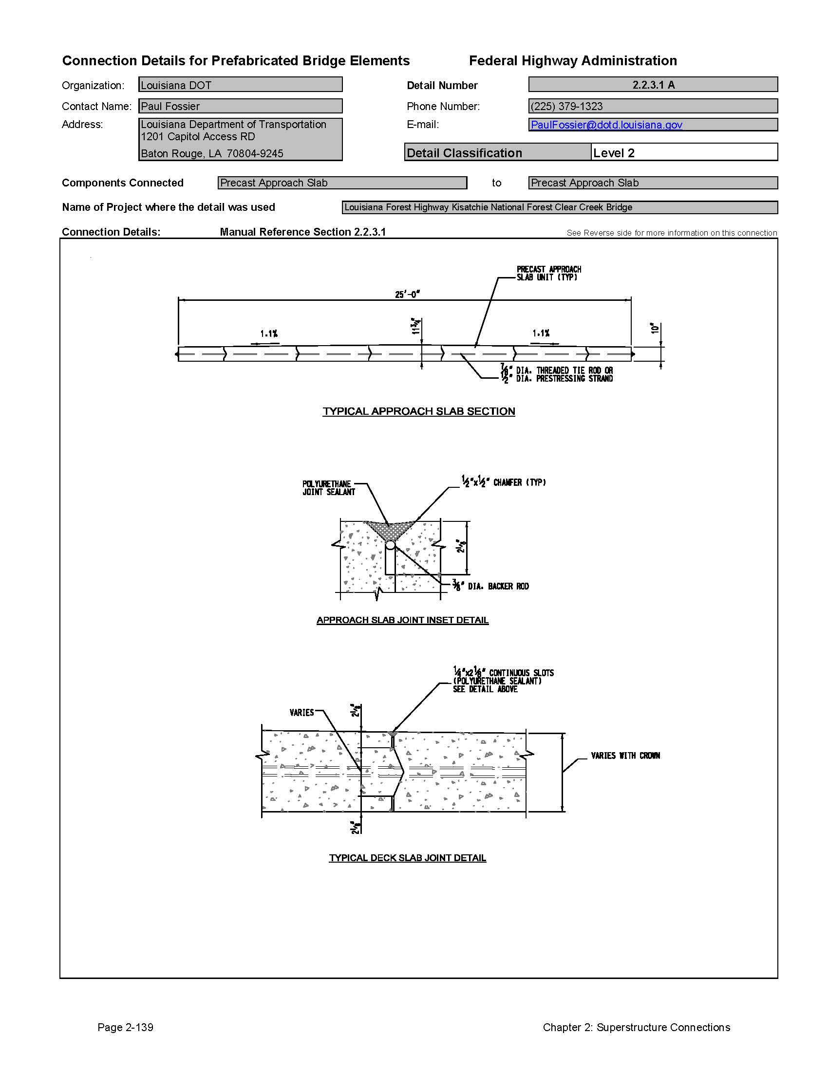
Louisiana DOT submitted details for precast approach slabs that are similar to details for precast adjacent slab systems. Since these details are essentially the same as deck slab systems, they have been included in this section. Additional details for connections of approach slabs to abutments can be found in Section 3.2.4.2.
Most states have standard details for connection of these systems, though only a few submitted details for publication in this Manual. It is recommended that users of this Manual refer to the applicable state standards for more information on the specific detail requirements of each state.
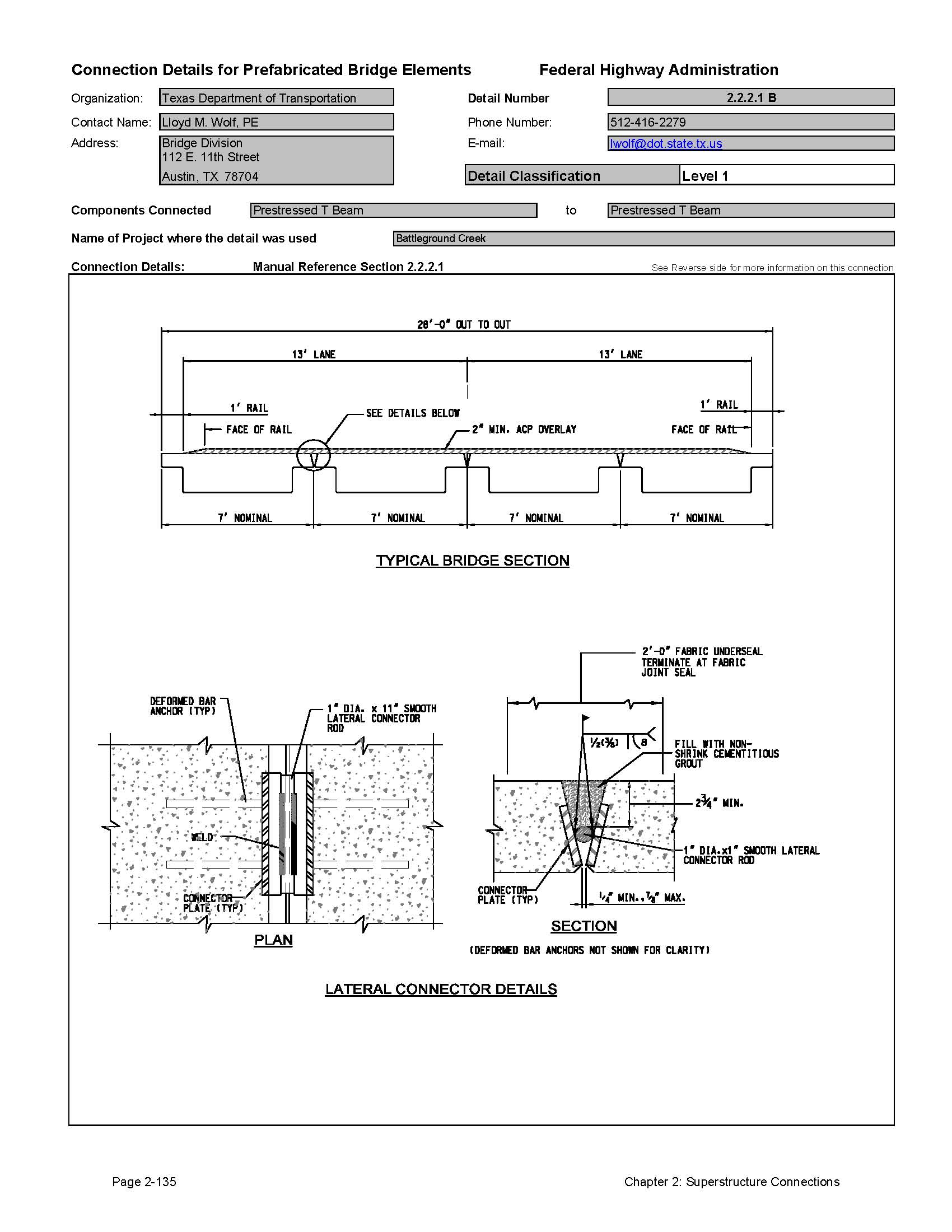
2.2.3.1 Connections Between Slabs and Between Adjacent Box Beams
Most of the states using these systems have standard details available on-line. The typical connection systems include a lateral tie system combined with a shear key filled with non-shrink grout. There are no design parameters for these connections in the AASHTO LRFD Design Specifications. The designs have evolved over the years on a trial and error basis. Louisiana has used similar connections to make longitudinal connections between precast approach slab elements.
Traditional Post-Tensioning and Bolted Systems
Most states use a transverse tie system to connect the beams. The ties range from simple threaded rods to sophisticated posttensioning systems. The spacing of the ties varies, but most are approximately 25 feet maximum on center. The amount of posttensioning force varies greatly from state to state. Some state use a little as 10,000 pounds per tie, others use over 60,000 pounds per tie.
The AASHTO LRFD specifications [1] have a recommendation for 250 psi transverse post-tensioning between deck slabs. This provision is not recommended for these connections because the connected elements are not deck slabs, and achieving this level of post-tensioning is not easily attainable. There has been research recommended for this connection by the Concrete Bridge Committee of the Transportation Research Board; however the research has not been funded to date. The Precast Prestressed Concrete Institute is also studying this connection. Users of this manual should keep apprised of future developments of these connections from these two organizations.
The ties are normally placed inside of holes that are cast through the width of the beams. Many states tension the ties prior to grouting the shear keys. The problem with this approach is that the post-tensioning force is taken up through friction in the bearings. Little or no force is actually applied to the interface between the beams.
In the northeast, the ties are tensioned after the grout is set. This approach places the actual grouted joint between the beams into compression, which is a preferred method of making this connection. This means that the post-tensioning system needs to be in a duct so that the shear key grout will not bind the tie. These states typically use an unbonded single strand tendon in a grease filled sheath. The anchorages are epoxy coated and the entire system is sealed with grease.
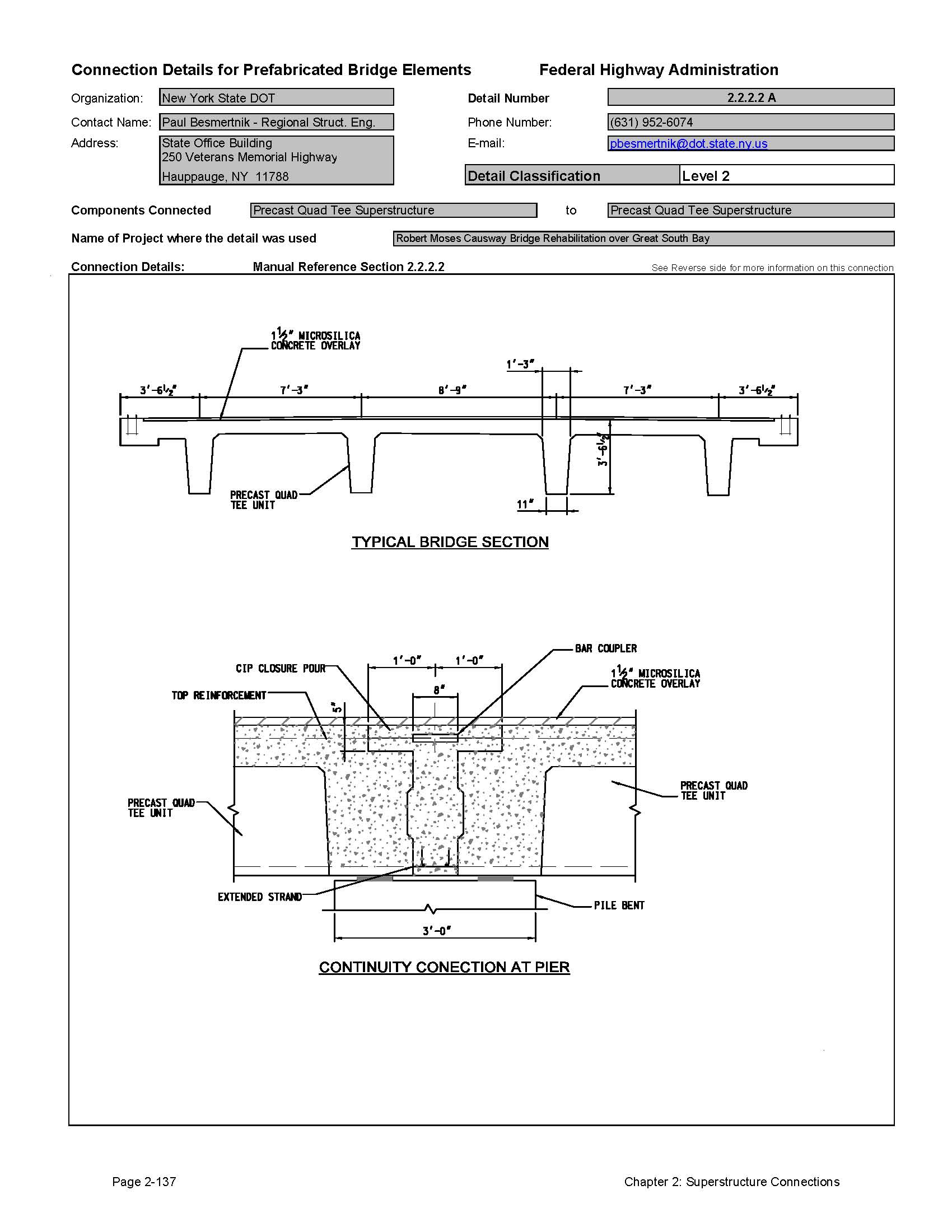
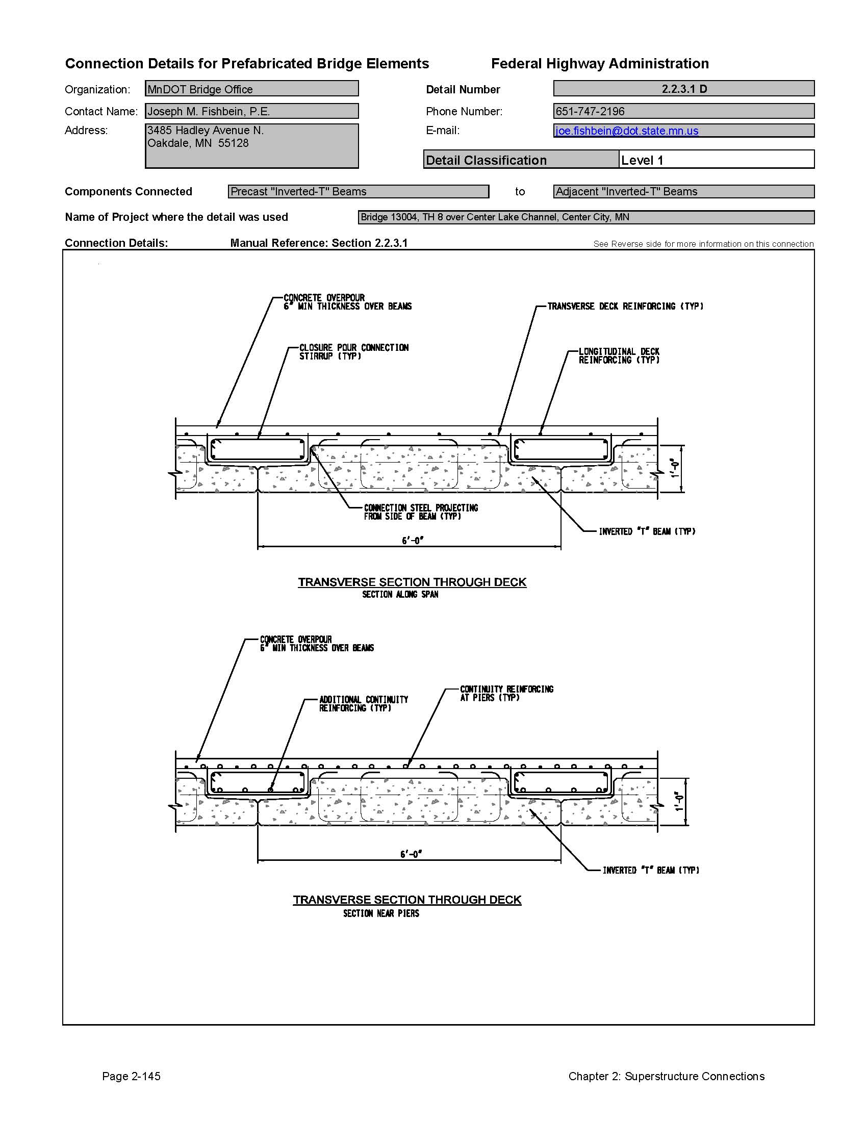
Reinforced Closure Pours
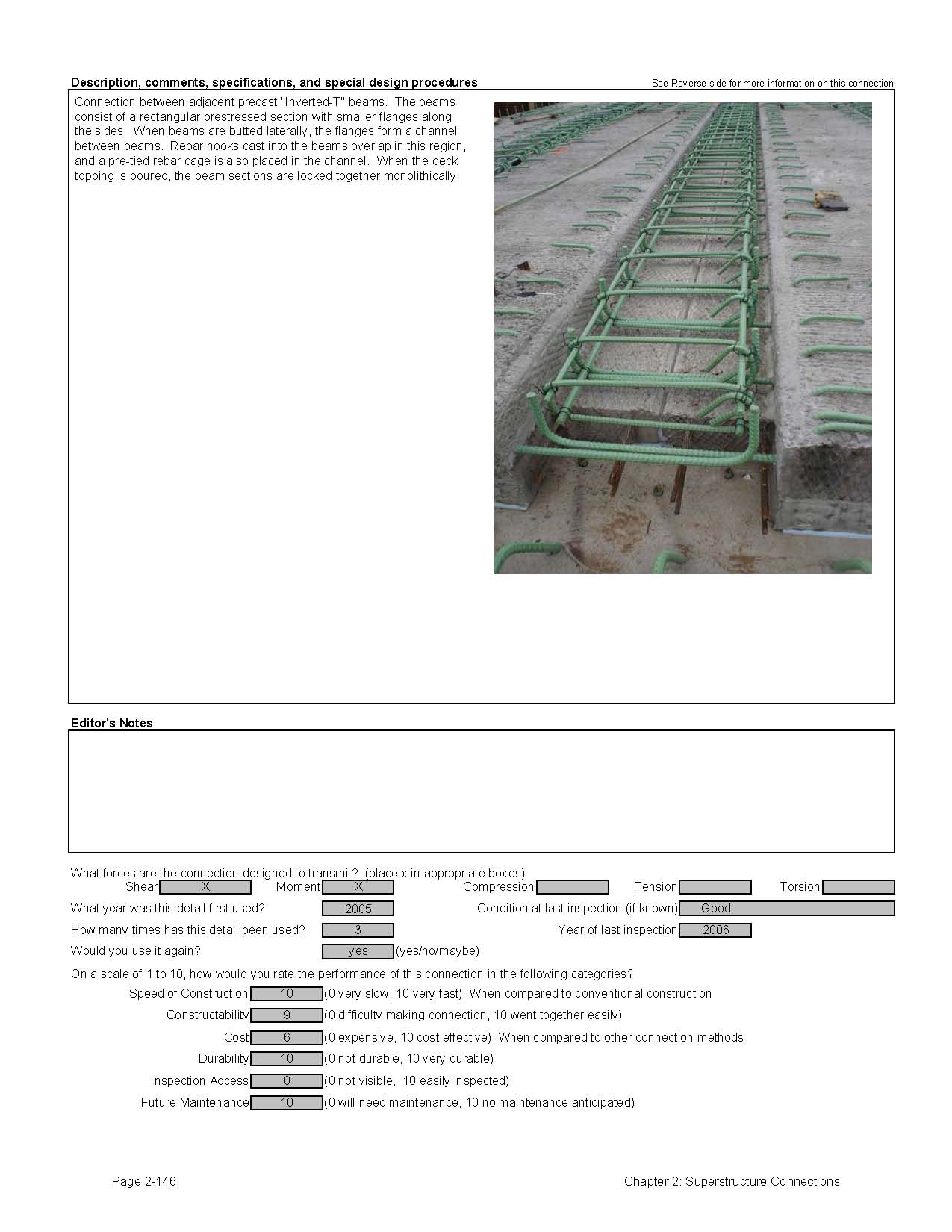
The Minnesota DOT has developed a new system based on a system developed in France. The important feature of this system is the connection between the beams. Lateral reinforcing steel projects from the sides of the inverted tee beams. Instead of a traditional grouted shear key, a large reinforced concrete closure pour is used between and over the adjacent inverted team beams to form the bridge deck. Figure 2.2.3.1-1 shows this system under construction. This system has been used successfully on several bridges in Minnesota.
Figure 2.2.3.1-1 Minnesota Adjacent Beam System
Welded Connections
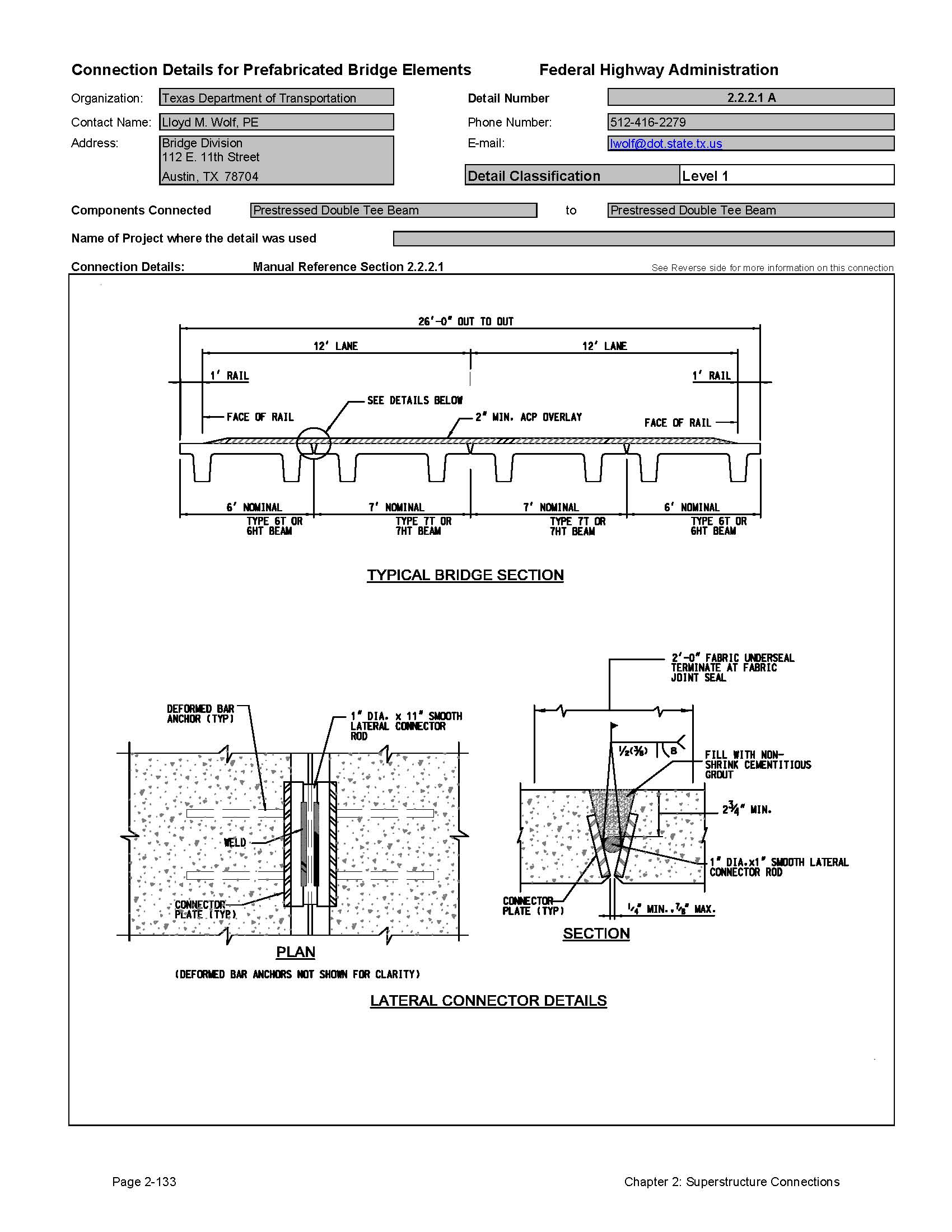
At least one state (Texas) uses a welded plate connection for adjacent deck slab bridges. Please refer to Section 2.2.1 for more information on welded connections.
2.2.3.2 Concrete Over Pours and Composite Toppings
To alleviate longitudinal joint leakage problems on higher volume roads, some states are now specifying reinforced concrete topping slabs over the adjacent beams. These slabs contain one reinforcing layer and are typically five to six inches thick. Even with the concrete topping, these bridges can be constructed much more rapidly than a conventional bridge with a cast-in-place deck because no forming is required to support the wet concrete.
2.2.4 Glue Laminated Timber Adjacent Deck Slabs
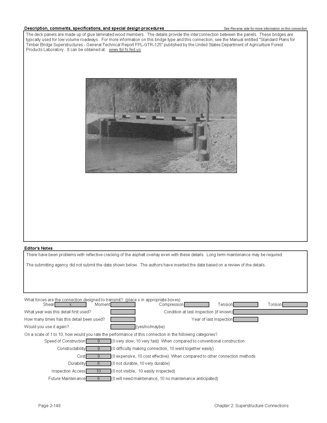
The United States Department of Agriculture Forest Products Laboratory (USDA FPL) has developed standard bridge details for timber bridges. These standards include prefabricated timber panels and beams. Most timber bridges are used on low volume roadways, but may be applicable to higher volume roads as well. Users of this Manual are encouraged to visit the USDA FPL for more information on timber bridges (www.fpl.fs.fed.us).
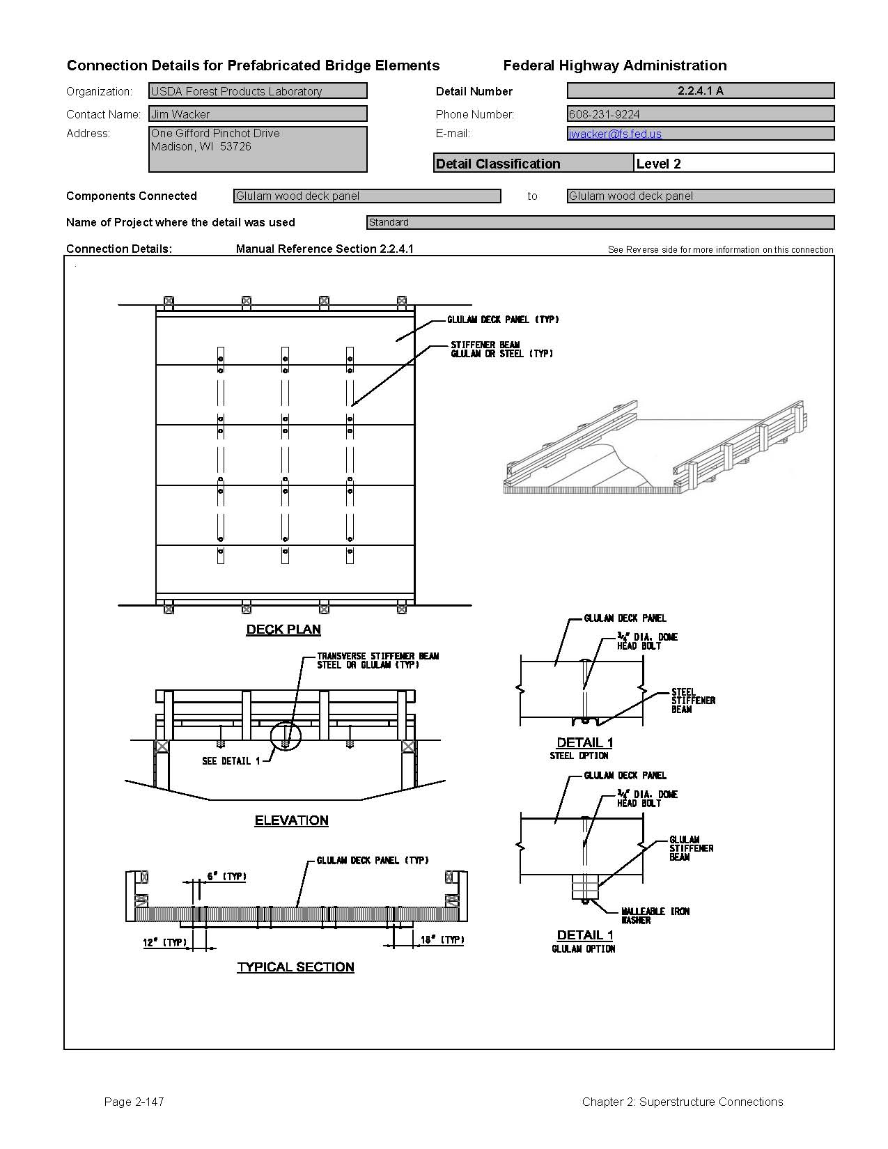
Short span bridges can be built using longitudinal glue laminated timber deck panels that span from support to support. The prefabrication involves gluing nominal dimension lumber side-by-side to create a solid panel. For deck slabs, the laminations have the wide face in the vertical direction. Protection against rotting is controlled by the use of pressure treated wood products. The individual laminations can be pressure treated before being laminated together, or the laminated pieces can be pressure treated after fabrication. The glue used for bridge application must be waterproof.
The connection between wood deck panels is used to transfer shear between the panels. Earlier versions of this system used only steel dowels placed mid-depth between the panels. This system proved to be problematic for higher volume roadways, especially when a bituminous wearing surface was employed. The connections would eventually loosen, leading to cracking of the pavement and leakage through the joints.
The current details include a load transfer beam placed at mid-bay between the support stringers. This beam provides a more significant shear transfer mechanism. Even with this connection, reflective cracking can occur in the overlay pavement. For this reason, it is recommended that a layer of geotextile fabric be installed between the pavement and the panels.
Another type of timber superstructure that has been used quite often is a nail laminated or stress laminated wood deck. These systems consist of dimensional lumber placed side by side that are either nailed together, or post-tensioned together. This type of construction can be completed in a relatively short amount of time. Connection details of laminated decks are not included in this manual because the decks are more of a system as opposed to a specific connection. Users of this Manual are encouraged to visit the Forest Products Laboratory website for more information on nail laminated and stress laminated timber decks (www.fpl.fs.fed.us).
2.2.4.1 Connections Between Slabs
The connection between wood deck slabs is used to transfer shear between the slabs. A load transfer beam placed transversely across the bridge at a specified spacing provides a shear transfer mechanism between the units.
2.2.5 Grade Control and Tolerances
Most adjacent butted systems are constructed with precast pretensioned concrete. Precast beams are normally cast flat and arrive at the project site with minor camber caused by the prestressing force. In order to build a bridge to a specified vertical profile, the thickness of the concrete topping or wearing surface must vary along the beam length to compensate for this camber. For bridges on crest vertical curves, the thickness of the topping or wearing surface will be thicker near mid-span. For bridges on sag vertical curves, the topping or wearing surface will be thicker near the supports. Designers need to account for these variations when designing the beams and setting the grades of the supports.
The grades of the roadway also affect construction of parapets and curbs. The variation in topping and wearing surface thickness must be applied to curb heights as well.
Normal tolerances specified in the PCI Manual entitled "Tolerance Manual for Precast and Prestressed Concrete Construction - MNL 135-00" should suffice for precast prestressed adjacent butted beam systems [16]. A nominal width joint is normally specified between the beams to account for the allowable sweep tolerance in the beams.
2.2.6 Evaluation of Performance and Long Term Durability of Adjacent Beam Systems
As previously stated, adjacent butted beam systems have proven very durable. Some bridges have been in service for over 50 years with no significant deterioration. Most problems with these systems are found on high volume roadways. It appears that the standard grouted shear keys with nominal lateral ties may not be adequate for high volume roads. An informal unpublished study was performed by the Connecticut DOT on failed grouted shear key connections on an Interstate highway bridge. Several joints were cored to inspect the grouted keys. Voids were discovered in the upper half of all joints, indicating that the mechanical interlock of the shear key was lost. Based on this discovery, it was determined that poor grouting techniques were employed during construction of the bridge, which led to the voids in the keyways. Even with this limited study, there is no consensus about the cause of leakage through longitudinal joints. The cause is either inadequate lateral posttensioning, or poor grouting techniques.
Several states are addressing this problem by adding reinforced concrete toppings to make a better connection between the beams. This has proven to be a successful way to minimize the problems with leakage through the joints.
The more traditional lateral tie systems with bituminous wearing surfaces appear well suited for local low volume roads. These bridges can be constructed rapidly with minimal field construction, and should require little or no maintenance for many years.
2.2.7 Estimated Construction Time for Connections
Timelines for construction depend on the weather and site-specific factors such as access, traffic control, and locations for cranes and storage. Nonetheless, it is possible to make reasonable estimates on construction time for the various systems discussed in this section.
Table 2.2.7-1 contains approximate installation times for the various adjacent butted beam systems included in this section:
| System | Minimum Installation Time* | Comments |
|---|---|---|
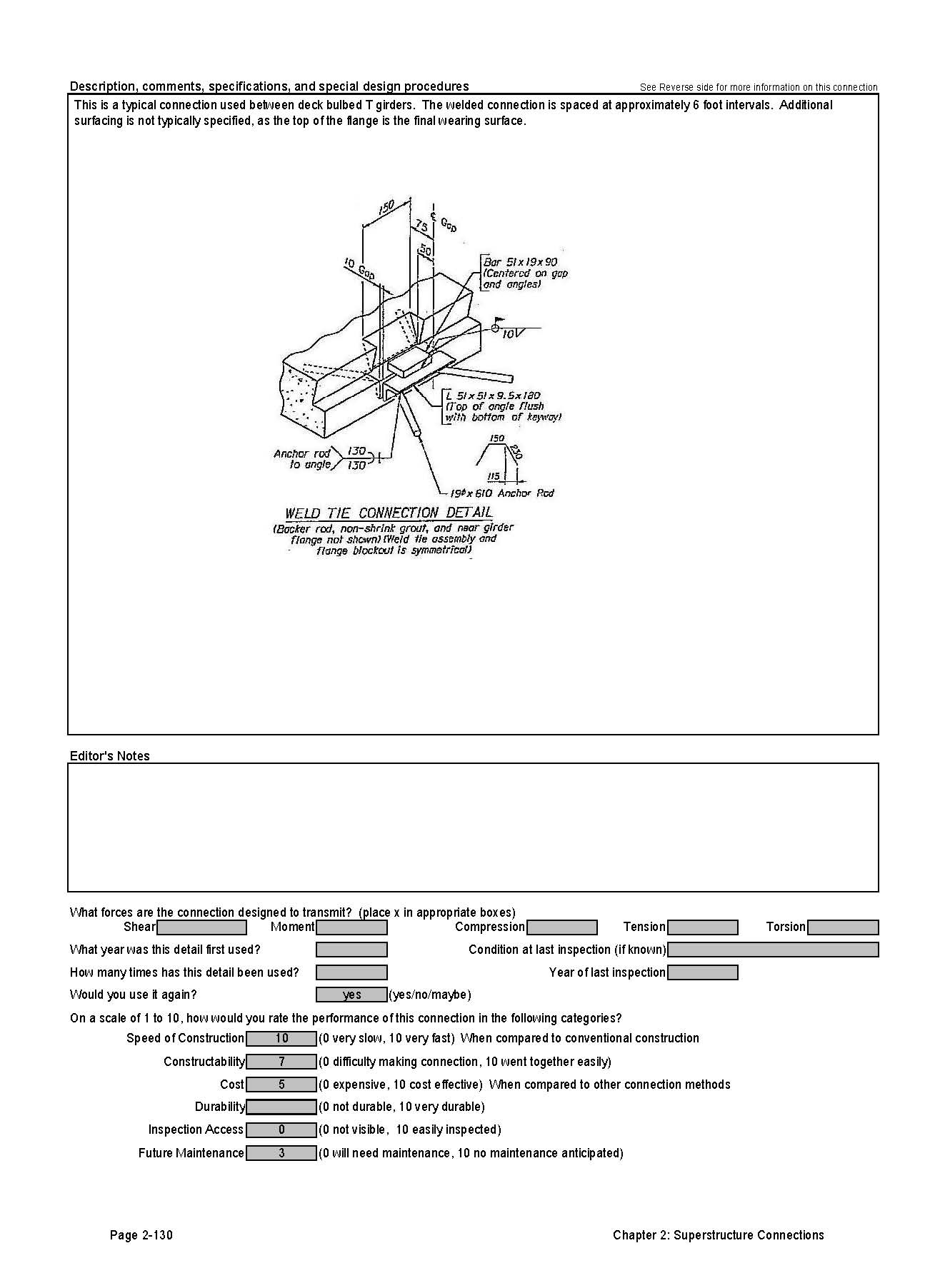
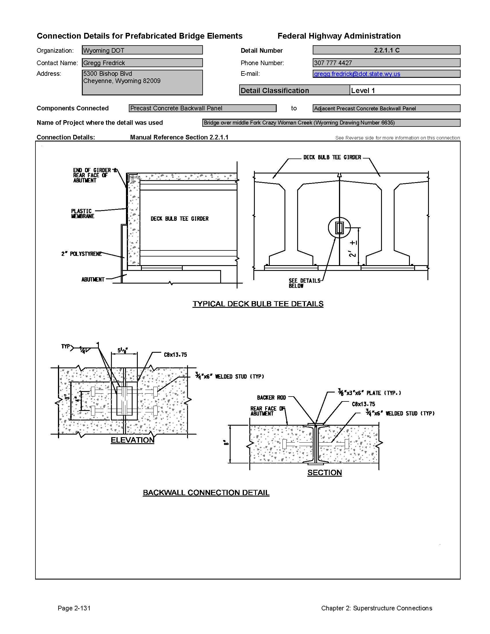
| Deck Bulb Tee Beams | 2 days | Includes erection, welding, and grouting |
| Tee Beams | 2 Days | Includes erection, welding, and grouting |
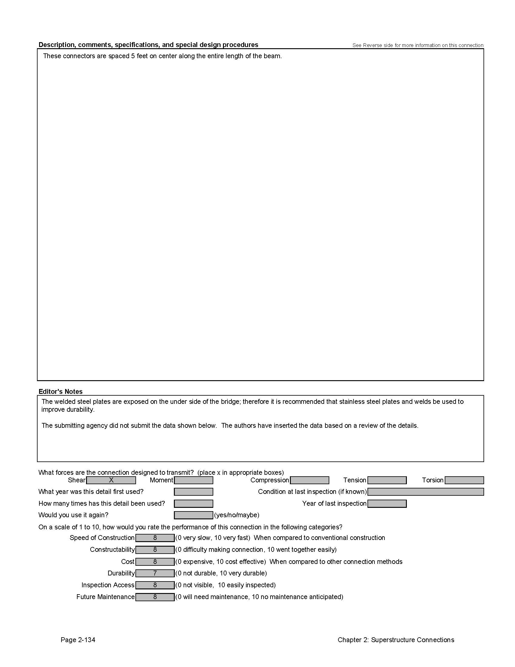
| Adjacent Deck Slab and Adjacent Box Beam Systems | 2 Days | Includes erection, welding or tie installation, and grouting |
* Times indicated are for a typical single span bridge. Multiple spans can be built in the same time frame with larger construction crews.
2.2.8 Recommendations for Improvements to Current Practices
Most problems with butted beam systems involve the adjacent deck slab and adjacent box beam systems. The leakage of the joints on high volume bridges without concrete toppings can be problematic. The concrete topping addresses this problem, but adds time and cost to the project. Additional research should study the grouted key construction combined with lateral post-tensioning to determine if a durable grouted key system is feasible.
2.2.9 Connection Detail Data Sheets for Adjacent Butted Beam Systems
The following pages contain data sheets for the various prefabricated butted beam systems. This information was primarily gathered from agencies that have developed and used the systems. Most data in the sheets were provided by the owner agency; the authors added text when an agency did not supply all requested information. The owner agencies also provide a comparative classification rating.
Each connection detail data sheet is presented in a two-page format. Users of this Manual can simply remove and copy a data sheet for use in developing a system for a particular project. These sheets are meant to give users a basic understanding of each connection that can be used during the type study phase of a project. The data sheets are not meant to be comprehensive, but do convey the component make-up of the detail, how it is meant to function, and provide some background on its field application. Users will need to investigate each connection further, consider site-specific conditions, and apply sound engineering judgment during design.
The key information provided for each connection is as follows:
- Name of the organization that supplied the detail
- Contact person at the organization
- Detail Classification Level
- Level 1
This is the highest classification level that is generally assigned to connections that have either been used on multiple projects or have become standard practice by at least one owner agency. It typically represents details that are practical to build and will perform adequately. - Level 2
This classification is for details that have been used only once and were found to be practical to build and have performed adequately. - Level 3
This classification is for details that are either experimental or conceptual. Details are included in this Manual that have been researched in laboratories, but to the knowledge of the authors, have not been put into practical use on a bridge. Also included in this classification are conceptual details that have not been studied in the laboratory, but are thought to be practical and useful.
- Level 1
- Components Connected
- Name of Project where the detail was used
- Manual Reference Section
- The section(s) of this Manual applicable to the particular detail shown.
- Connection Details
- Description, comments, specifications and special design procedures
- Forces that the connection is designed to transmit
- Information on the use of the connection (including inspection ratings)
- A performance evaluation of the connection rated by the submitting agency
Click images below to enlarge
Detail 2.2.1.1A

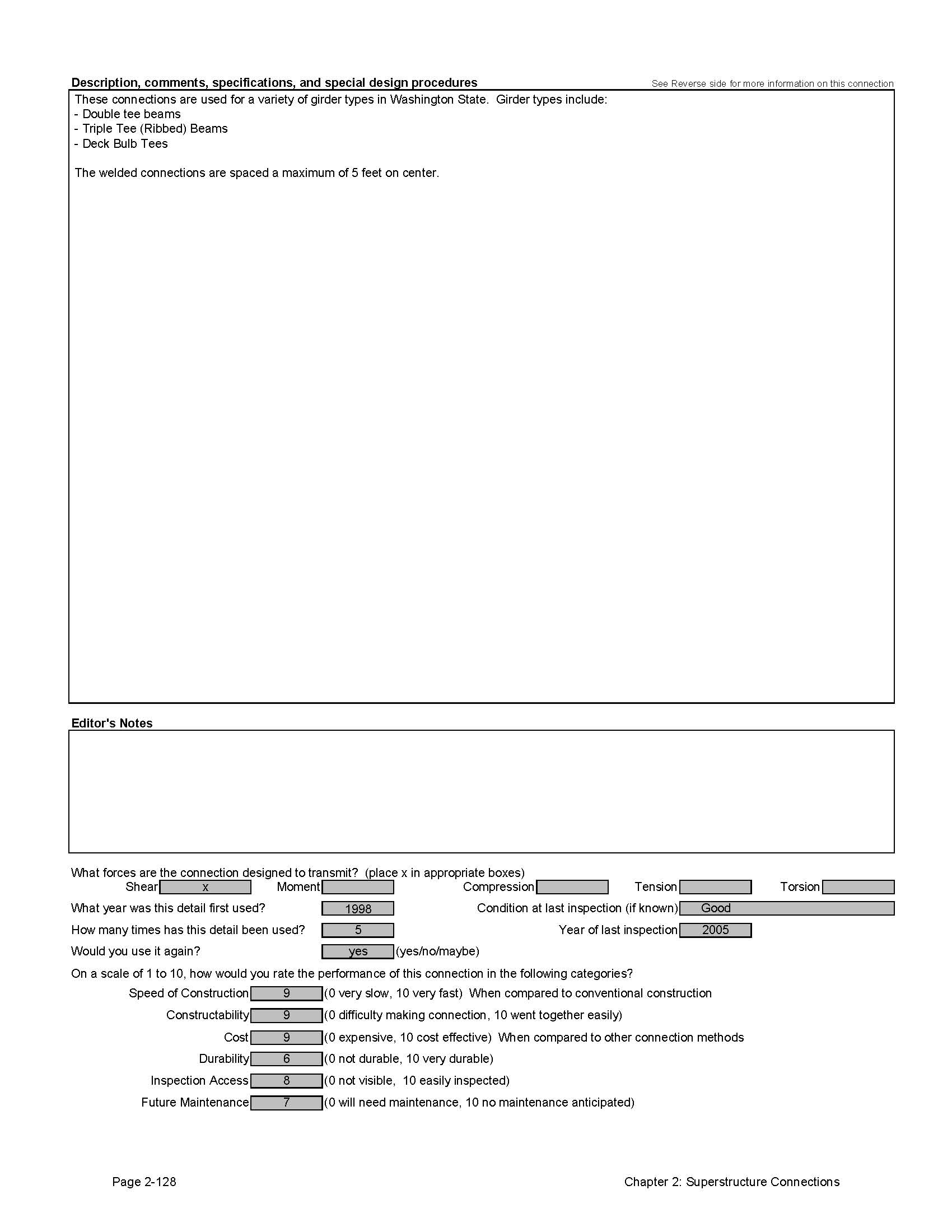
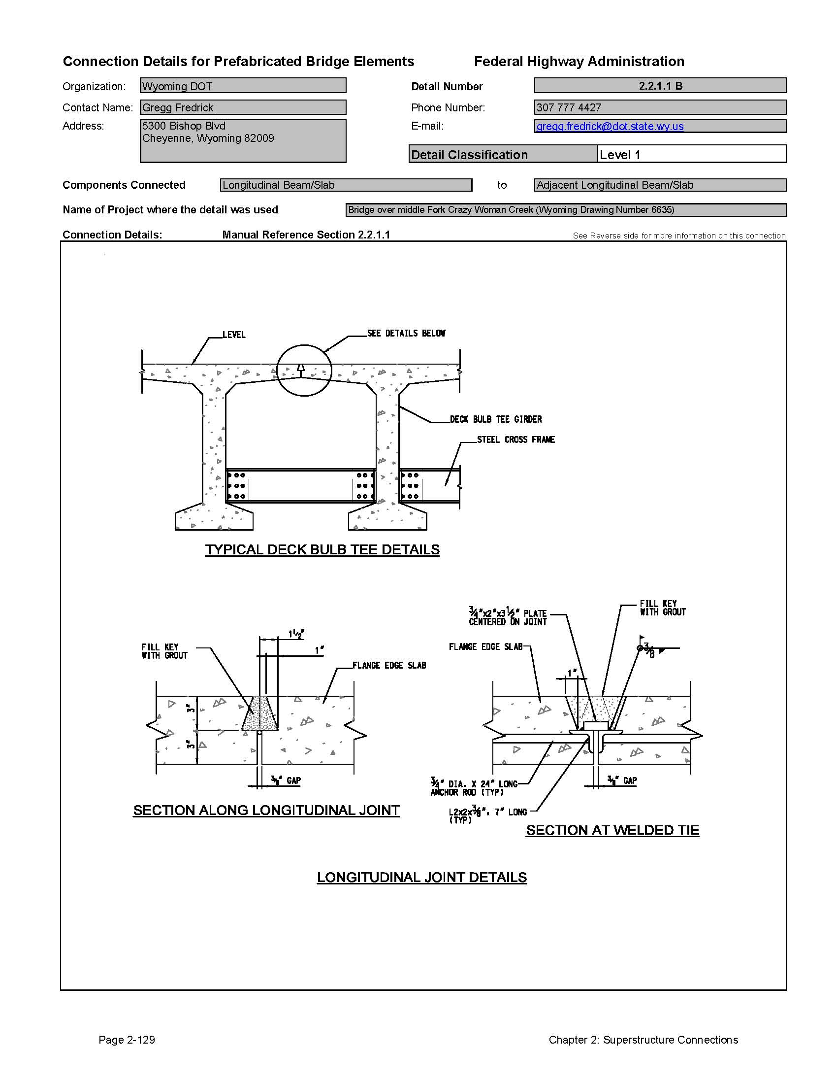
Detail 2.2.1.1B
Detail 2.2.1.1C

Detail 2.2.2.1A
Detail 2.2.2.1B

Detail 2.2.2.2A

Detail 2.2.3.1A

Detail 2.2.3.1B


Detail 2.2.3.1C


Detail 2.2.3.1D
Detail 2.2.4.1A
2.3 Decked Stringer Systems
This section focuses on connections between traditional parallel superstructure stringer beam elements, the most common form of bridge in use today. The connections presented include both transverse connections and longitudinal beam splices.
2.3.1 Transverse Connections
The transverse connection between parallel beam elements is referred to as a cross frame or diaphragm. These connections serve to:
- Assist with lateral distribution of load in the structure
- Provide lateral stability of the beams during construction
- Transfer wind loads from the fascia beam to the interior beams and deck slab.
2.3.1.1. Connections Between Steel Beams
Diaphragms and cross frames for steel bridges are easily attached by bolting or welding. State agencies have standard details for these connections; therefore, they are not presented in this Manual. Most diaphragms and cross frames have bolted connections. To expedite construction, designers should keep the number of bolts required for these connections to a minimum.
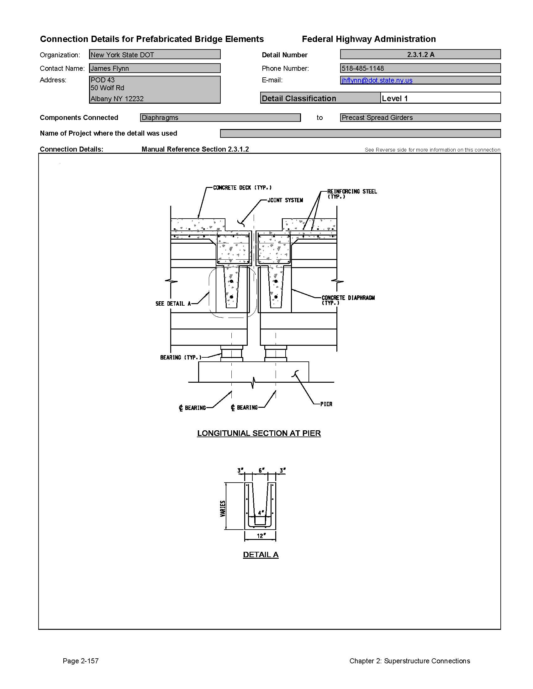
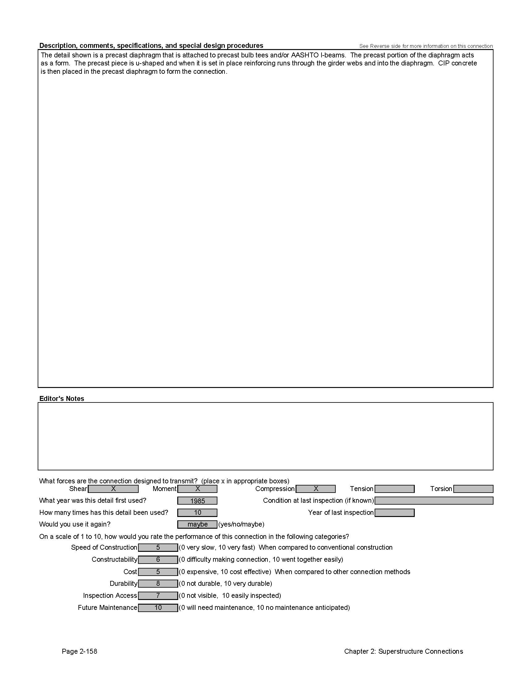
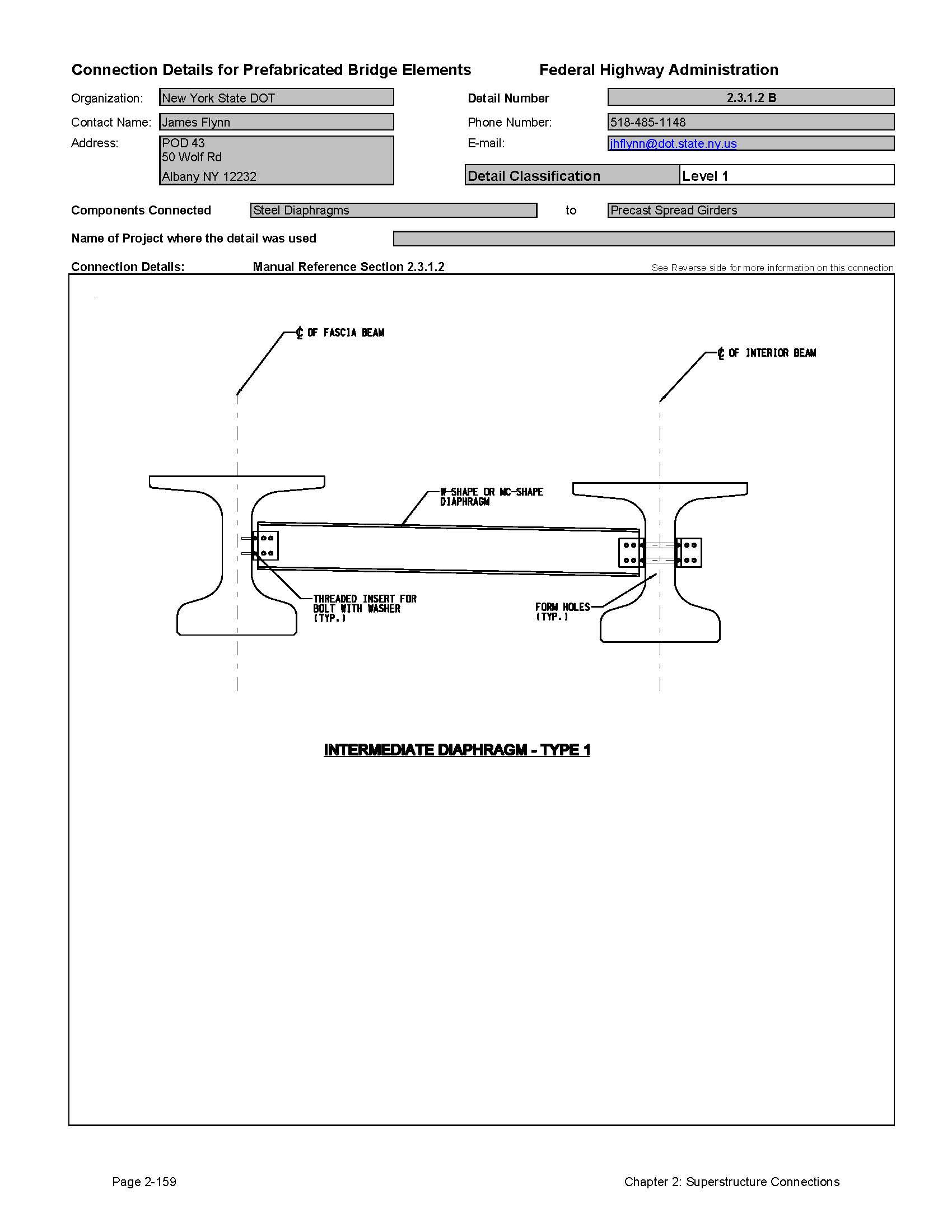
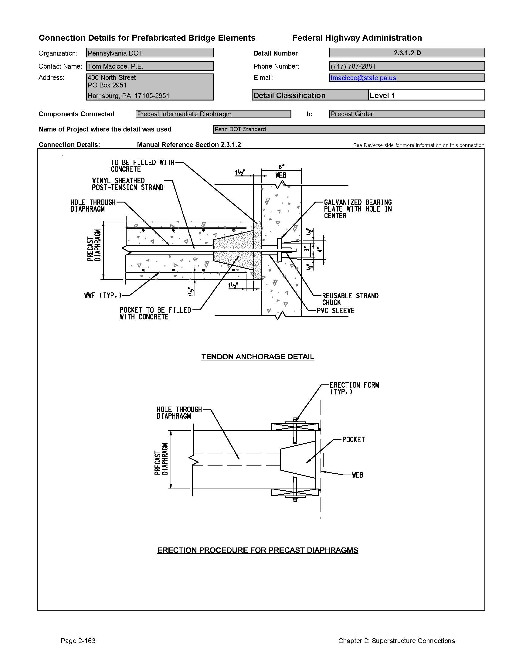
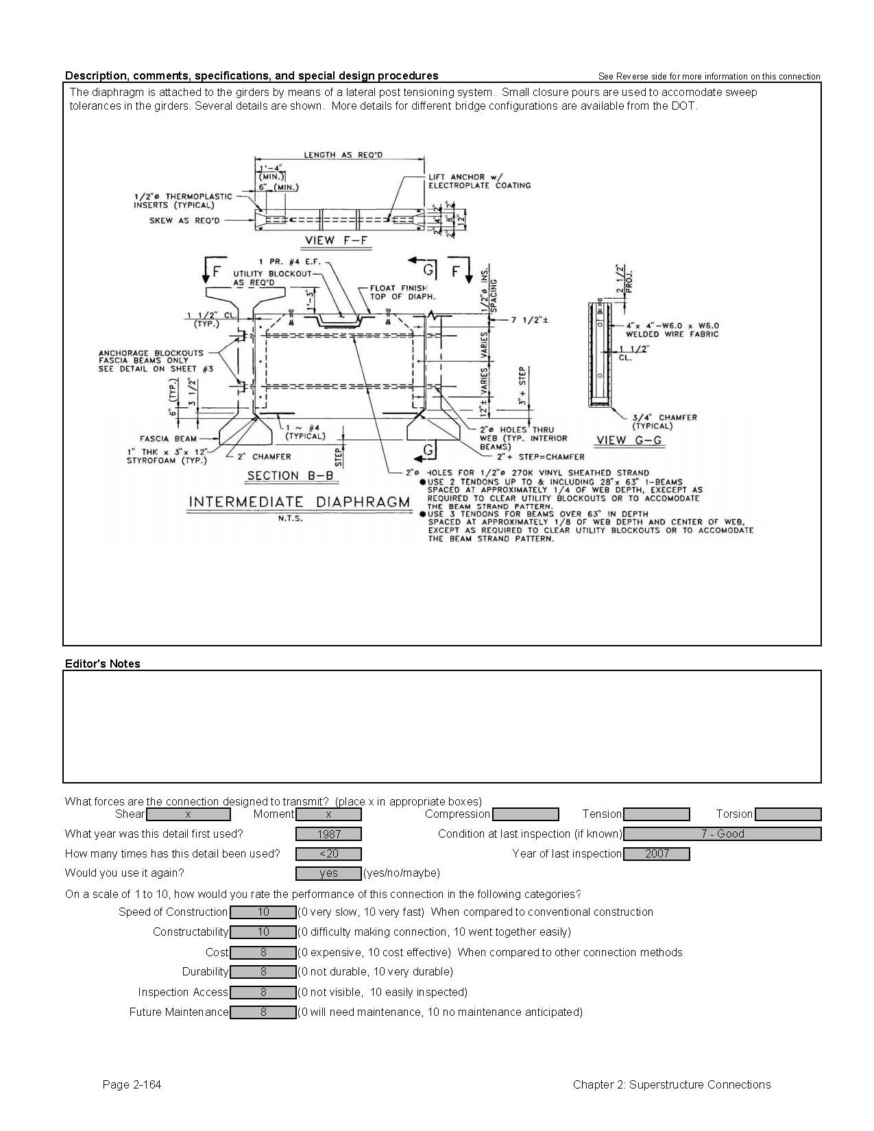
2.3.1.2 Connections Between Prestressed Precast Beams
Diaphragms and cross frames for prestressed precast concrete beams are typically more difficult to build than steel bridge members. Often, these elements are made using cast-in-place concrete. The time for forming and curing of the connections can be significant. This section contains details for prefabricated diaphragms and cross frames that have been developed by several states. They include both steel bolt-on diaphragms and precast diaphragm forms.
2.3.2 Longitudinal Connections
2.3.2.1 Steel Beams
Longitudinal connections for steel beams are commonly referred to as beam splices. The most common form of beam splice is a bolted connection. These connections can be quite large and contain numerous bolts; however, in most cases, several connections can be made in one day.
There are ways to expedite the erection of steel beams with bolted splices. The critical time constraint on a steel beam erection site is the time that the cranes are idle while the connections are made. Two things can be done to expedite this process. First, an erection tower can be used to rest the beams after they are set. Second, the designer can allow for early release of the beam by the cranes after a certain number of bolts are installed. The National Steel Bridge Alliance recommends the following practice [42]:
"For splice connections of primary members, as well as connections of diaphragms or cross frames designed to brace curved girders, fill at least 50 percent of the holes prior to crane release. The 50 percent may be either erection bolts in a snug tight condition or full-size erection pins, but at least half (25 percent of all holes) shall be bolts, and sufficient pins shall be used near outside corners of splice plates and at member ends near splice plate edges to ensure alignment. Uniformly distribute the filled holes.
The 50 percent requirement may be waived if a reduced percentage is calculated as sufficient and shown on the approved erection procedure."
Welded field splices are not as common as bolted splices. Temporary support towers are usually required to complete a welded field splice.
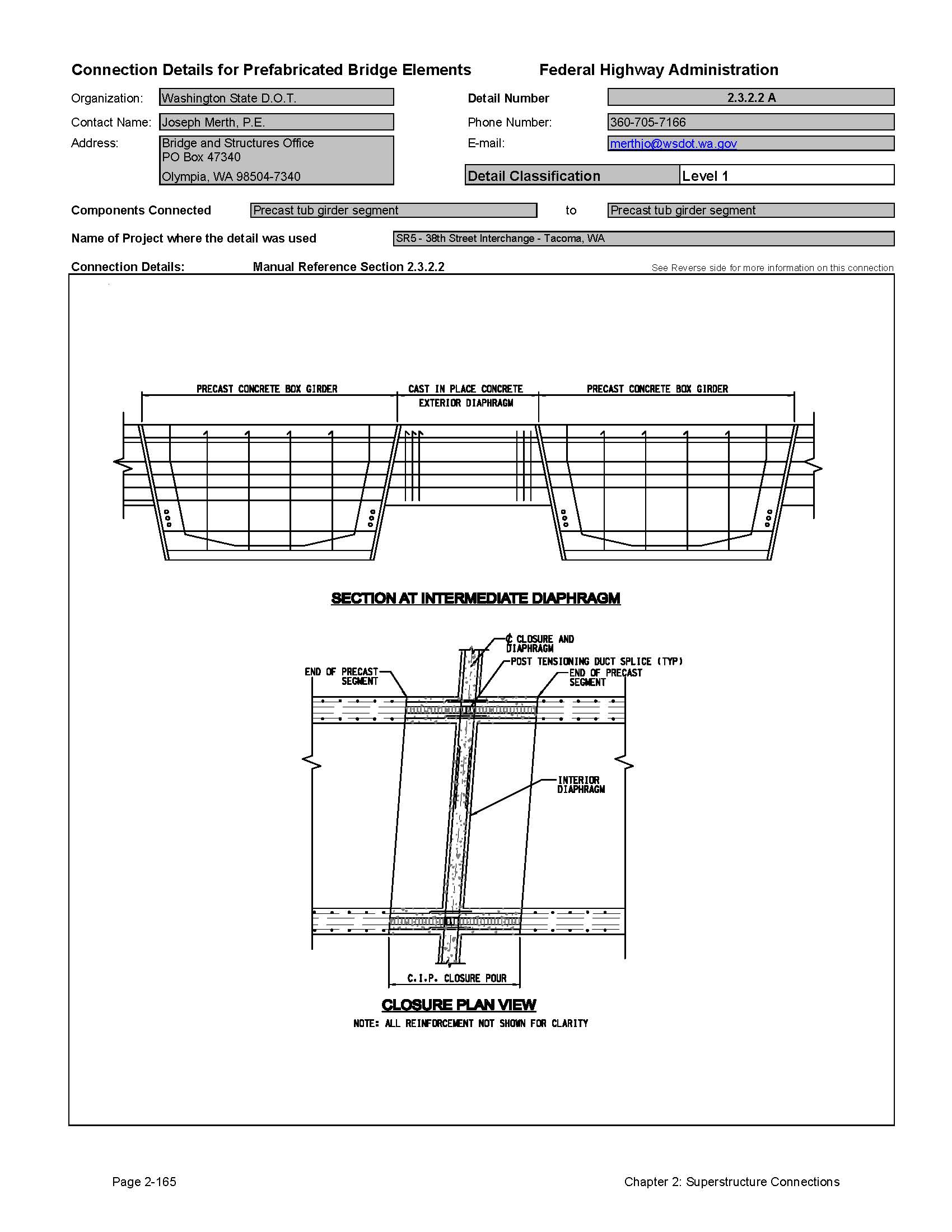
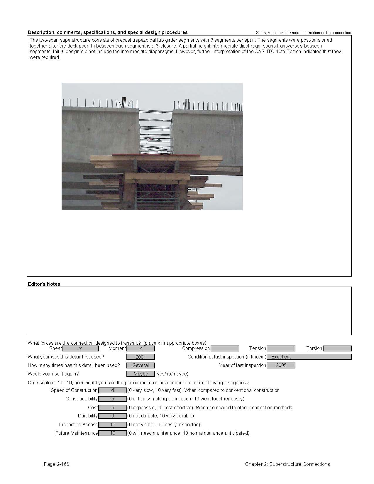
2.3.2.2 Prestressed Precast Concrete Beams
There are two methods used to splice a prestressed precast concrete beam. The most common splice involves a concrete closure pour combined with longitudinal post-tensioning. Closure pours are used because precast beam elements will arrive in the field with some residual camber from prestressing. The camber leads to beam end rotation that is variable and difficult to estimate. The closure pour can accommodate variations in beam end angles and also allow for minor length tolerance adjustments. The closure pours are reinforced with steel projecting from the beam element and often include shear keys. The post-tensioning ducts are simply spliced within the closure pour area.
The second method that has been used is to match cast the two adjacent elements in the fabrication shop. This method can be problematic if there is any measurable prestress in the beams that would lead to camber growth. Match casting should only be used for beams with little or no pretensioned prestressing.
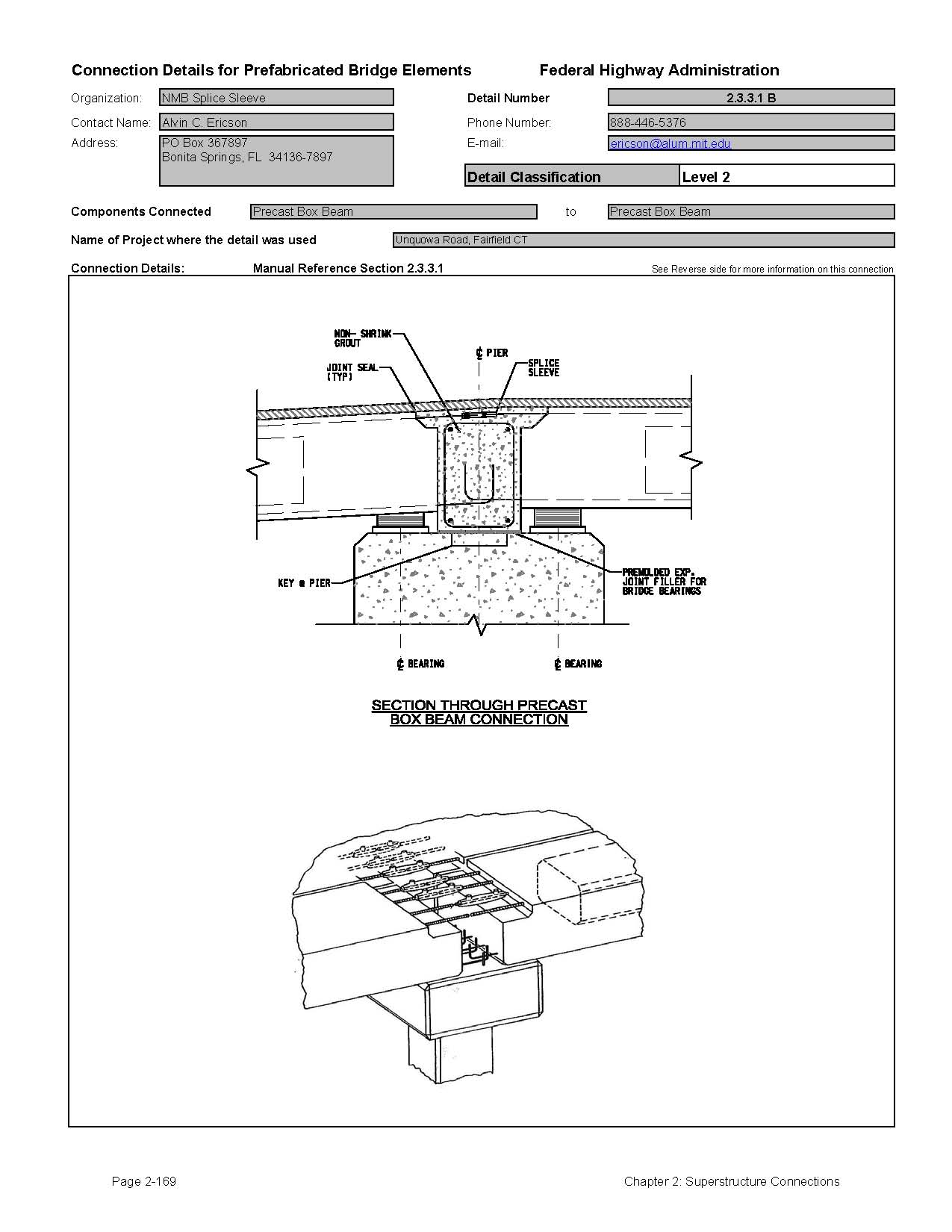
2.3.3 Simple Span Beams Made Continuous For Live Load
It can be cost effective to construct multi-span bridges that act as simple spans for dead loads and continuous spans for composite dead loads and live loads. This is accomplished using the following construction procedure:
- Erect the beams spanning from support-to-support without a continuity connection at the supports. The beam ends are butted with a minor gap at the piers.
- Cast the bridge decks over the spans but not over the beam ends at the pier.
- Connect the beams by casting a block of concrete between the beam ends. This pour usually includes an integral diaphragm.
- Cast the bridge deck over the pier closure pour. Negative moment reinforcing is normally placed within the deck in this area. The deck is sometimes cast with the beam end closure pour. Page 2-150 Chapter 2: Superstructure Connections From this time forward, the bridge acts as a continuous span because the closure pour is designed to transfer the subsequent composite dead load (e.g., median barrier, parapet, sidewalk) and live load moments from one beam end to the adjacent beam end.
- Complete the bridge construction.
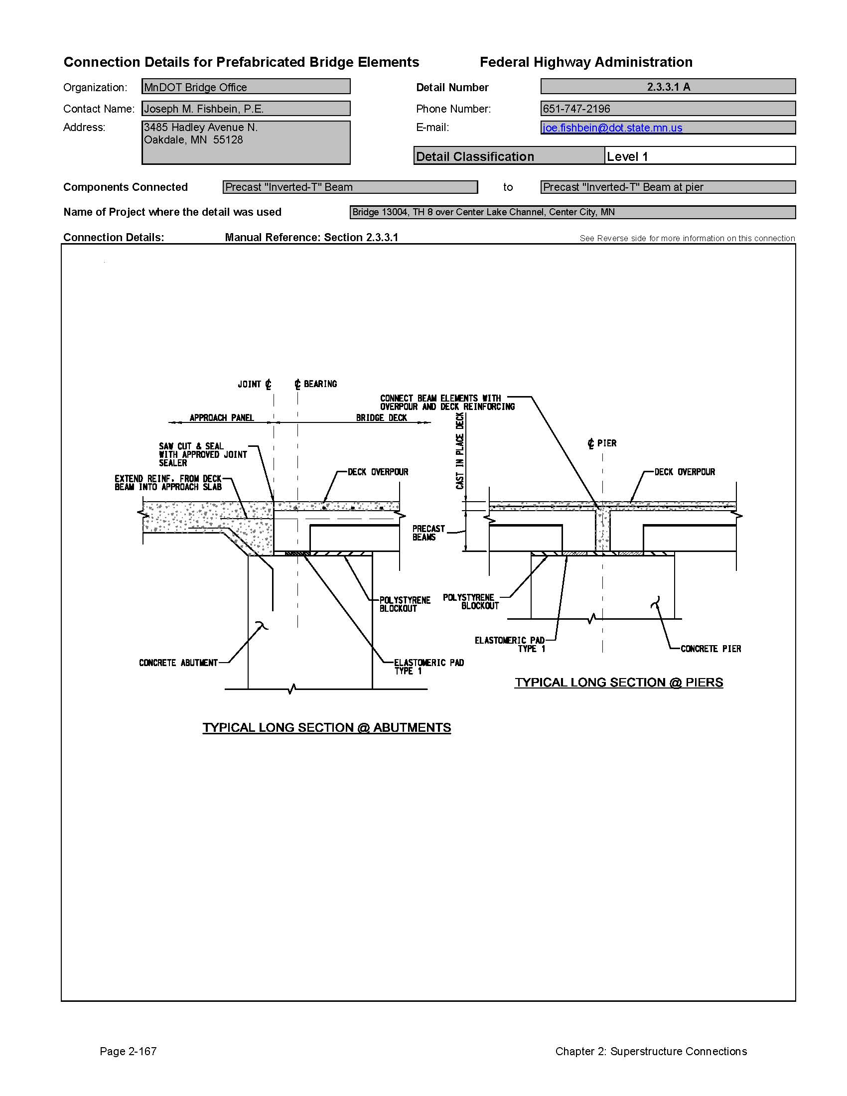
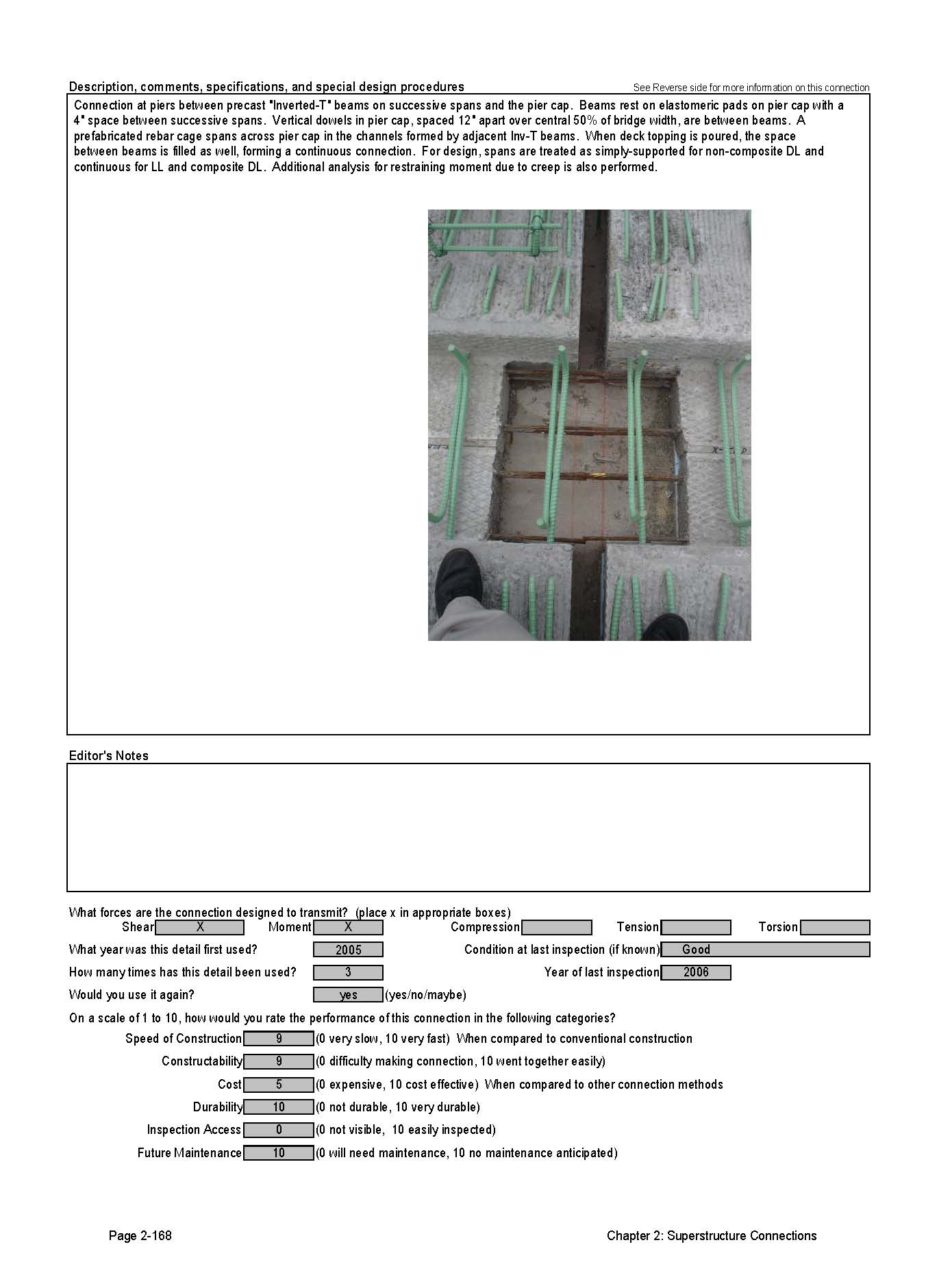
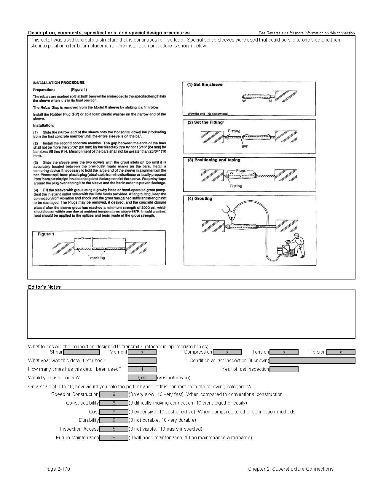
2.3.3.1 Prestressed Precast Concrete Beams
The prestressed concrete industry has been making precast concrete beams for many years. There are special considerations that need to be addressed in a design with prestressed concrete beams. Prestressed concrete beams will continue to experience camber growth after prestress release. Camber growth results in minor rotation of the ends of the beams. After the beams are connected at the piers, the camber growth will either crack the closure pour, or create positive moments in the connection. There have been several research projects regarding this connection. The most commonly reference document is NCHRP Report 322 entitled "Design of Precast Bridge Girders Made Continuous." The basic issues noted in this research are discussed in the following paragraphs.
Different states use different approaches to address the camber growth phenomenon. Some states use little reinforcing in the connection and allow it to crack. Once the crack forms, the connection will be free to rotate and the bridge will behave as a simple span bridge for live load because of the hinging effect of the cracked connection. Even with the cracking, there are advantages to this connection; the bridge will still be jointless and more durable than a simple span bridge with a deck joint.
Another approach to this connection is to reinforce the connection to resist the positive moments at the piers that are generated by camber growth. This will lead to positive moments along the span due to prestress, but will provide significant negative moment capacity that can decrease positive moments along the span. There are two methods used to create the positive moment connection within the closure pour. The first is to extend a number of prestressing strands into the closure pour by bending them near the face of the beam end. The second method is to embed mild reinforcing steel in the beam that protrudes from the beam end and into the closure pour. With either method, the long term internal stresses in the beams need to be calculated and checked, and the negative moment reinforcing in the slab needs to be designed.
Although engineers are taught that continuous span designs are more efficient than simple span designs, simple span structures without deck joints described above can also be efficient, cost effective, and quickly built. The efficiencies are seen primarily in the negative moment regions. A large portion of the sharp moment gradients near interior supports are shifted to the positive moment regions. An added benefit to the simple span designs described above is that the deck joint over the pier will be eliminated, thereby reducing the potential for future deterioration of the underlying framing and foundations. Depending on the design, minor cracking may occur at the pier, but this can be controlled with waterproofing membranes or in dryer climates, left alone. Also, simple-span construction allows simplified future replacement of beams, e.g., when damaged from below by over height loads, and simplified future widening.
State agencies have standard practices for the design and detailing of this connection. Many use the jointless simple span approach due to the simplicity of the design and detailing. Designers should refer to the specific state standards for this connection. If none exist, the authors of this manual recommend the approach developed by the New Hampshire DOT that is available through the PCI Northeast Bridge Technical committee. The committee has prepared a concise design and detailing guide based on methods developed by the New Hampshire DOT [43].
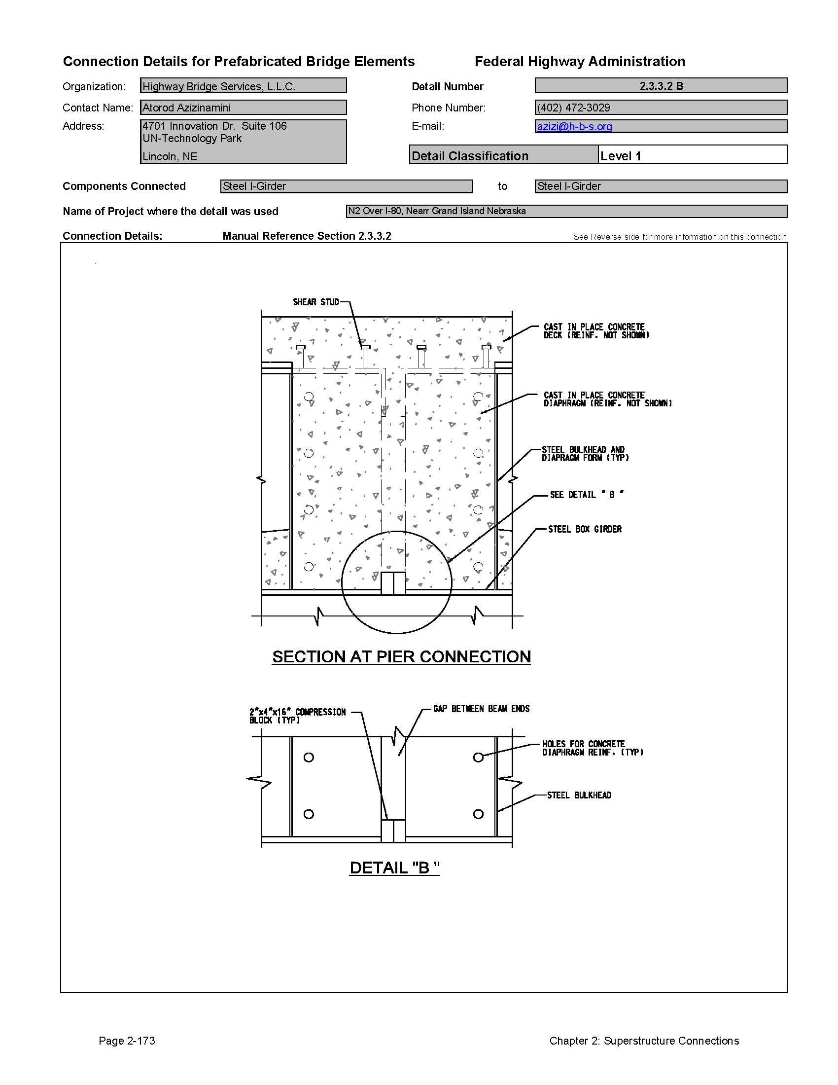
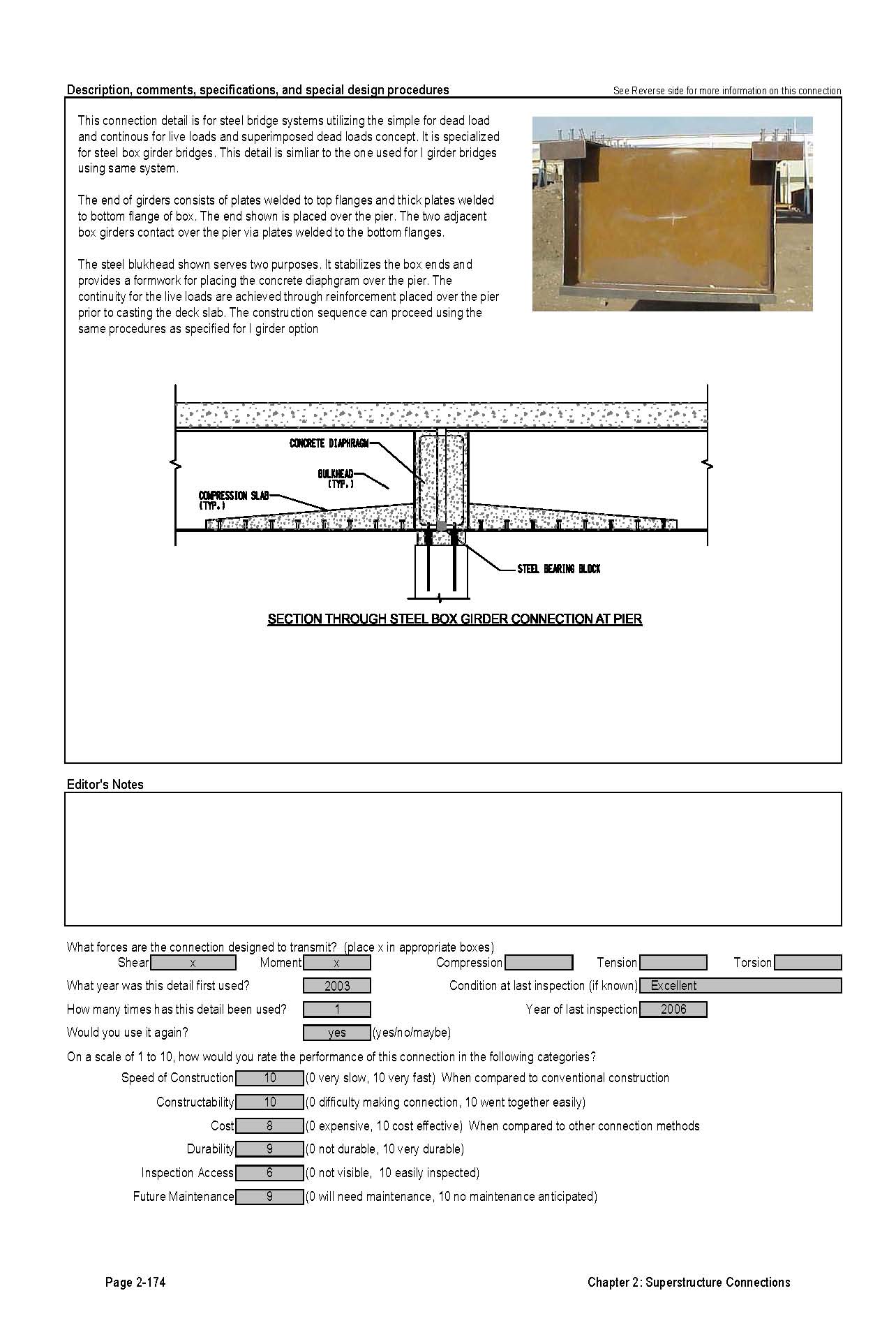
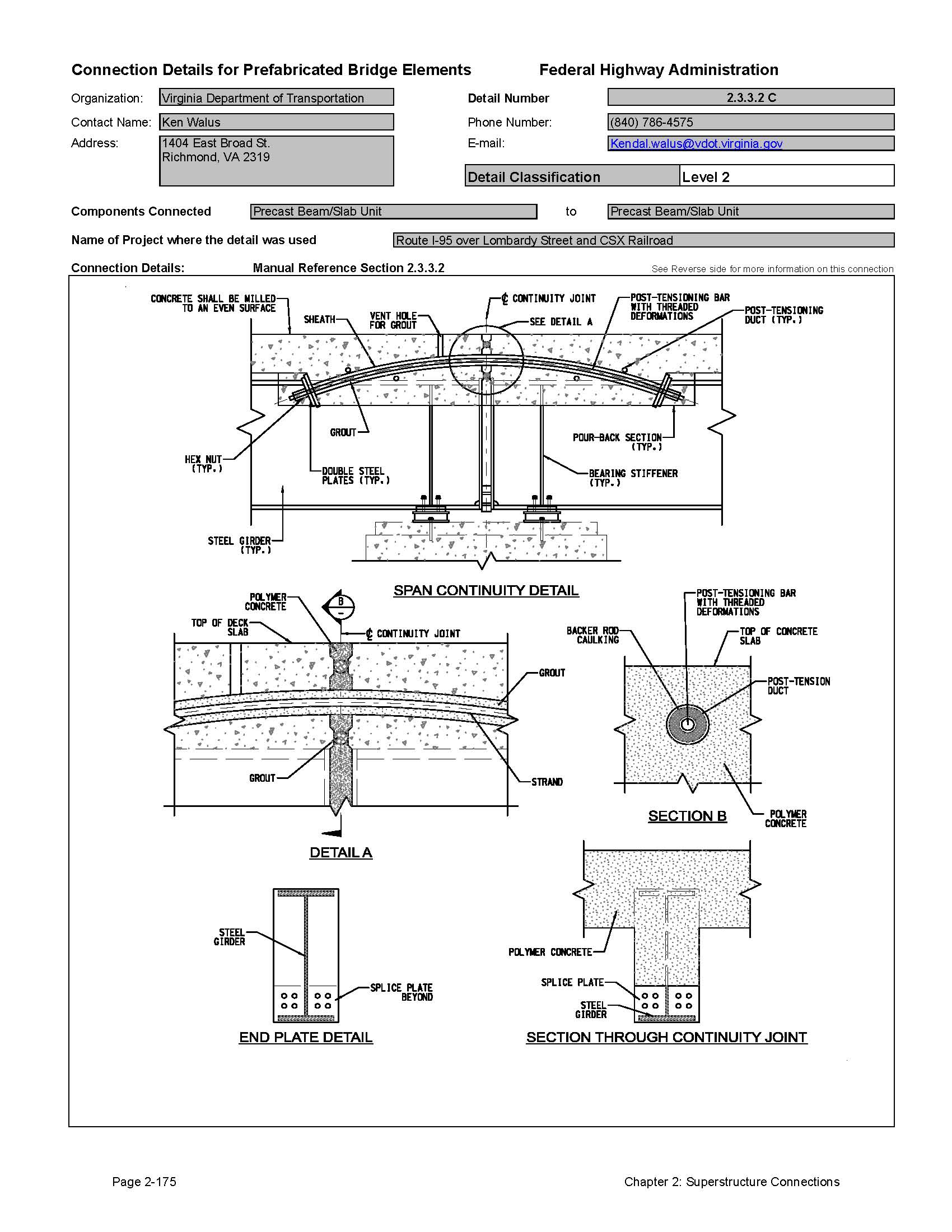
2.3.3.2 Steel Beams
This method of construction is primarily used by the precast prestressed concrete industry; however, the approach can also be applied to steel beam bridges. There has been recent research into the use of multiple simple span steel bridges that are made continuous for live load only. The idea is to erect each span as a simple span and then make a simple connection at the supports using cast-in-place concrete. This connection eliminates the need for significant field bolting or welds, allowing the cranes to release the beams immediately after they are in position, greatly reducing erection time.
Several states have used this method to make older simple span bridges continuous for live load during deck replacement projects. Once the deck is removed, the bottom flanges can be connected with welded plates. The bridge deck can be designed to act as the tension flange by reinforcing the deck over the pier, thereby eliminating the need for a top flange tension splice. Welded stud shear connectors complete the top flange connection by joining the deck slab to the beams.
2.3.4 Tolerances
Tolerances play a key role in transverse connections between longitudinal beam elements.
Steel beams are fabricated to specific cambers; however, tolerances in manufacturing can affect the cross frame connections. This is not usually an issue because the beams are quite flexible. Some designers have specified the use of slotted holes to accommodate camber tolerance. This approach is not recommended because it can lead to a buildup of erection misalignments. The steel industry suggests simply designing these connections with standard bolt holes.
Concrete beams can be more problematic because the beam camber is constantly changing due to the prestress forces. It is not unusual for camber to vary from one beam to another. The connections need to address this differential camber potential. Slotted holes in steel cross frames and adjustable forms for closure pours are often employed.
2.3.5 Evaluation of Performance and Long-Term Durability of Stringer Beam Systems
Some of the connections discussed in this section are located below the bridge deck and are therefore not subject to corrosive environments. One connection that can have a significant effect on long term durability is the continuity connection on bridges that are designed as continuous for live load. The elimination of deck joints is one of the most effective ways to improve the durability of the entire bridge structure. Leakage from deck joints can cause damage to the beam framing and foundations.
2.3.6 Estimated Construction Time for Connections
The times required for construction depend on a number of factors including site access, traffic control, weather, crane locations and proximity to storage areas. Nonetheless, it is possible to make reasonable estimates of the minimum required construction time for the various systems discussed in this section.
Table 2.3.6-1 provides approximate installation times for various decked stringer systems:
| System | Minimum Installation Time* | Comments |
|---|---|---|
| Cast-in-place concrete diaphragm on PS beams | 2 Days | Time includes forming multiple diaphragms and placing of concrete. |
| Precast diaphragms on PS beams | 1 Day | Multiple diaphragms can be completed in one day |
| Steel cross frames on PS beams | 1 Day | Multiple cross frames can be completed in one day |
| Bolted beam splices on steel beams | 1 Day | Except for very large connections, in most cases multiple connections can be completed in one day. |
| Welded beam splice on steel beam | 2 Days | Large beam splices may take longer |
| Cast-in-place closure pour splice on PS beams | 2 Days | Time includes forming multiple splices and placing of concrete |
| Live load continuity connections on concrete and steel beams | 3 Days | Time includes forming multiple closure pours and placing of concrete |
*The time for cast-in-place concrete is based on the use of high early strength concrete that can be cured rapidly.
2.3.7 Recommendations for Improvements to Current Practices
The connections described in this section are quite common and well tested. They result in durable stable connections.
2.3.8 Connection Detail Data Sheets for Decked Stringer Systems
The following pages contain data sheets for the various decked stringer systems. This information was primarily gathered from agencies that have developed and used the systems. Most data in the sheets were provided by the owner agency; the authors added text when an agency did not supply all requested information. The owner agencies also provide a comparative classification rating.
Each connection detail data sheet is presented in a two-page format. Users of this Manual can simply remove and copy a data sheet for use in developing a system for a particular project. These sheets are meant to give users a basic understanding of each connection that can be used during the type study phase of a project. The data sheets are not meant to be comprehensive, but do convey the component make-up of the detail, how it is meant to function, and provide some background on its field application. Users will need to investigate each connection further, consider site-specific conditions, and apply sound engineering judgment during design.
The key information provided for each connection is as follows:
- Name of the organization that supplied the detail
- Contact person at the organization
- Detail Classification Level
- Level 1
This is the highest classification level that is generally assigned to connections that have either been used on multiple projects or have become standard practice by at least one owner agency. It typically represents details that are practical to build and will perform adequately. - Level 2
This classification is for details that have been used only once and were found to be practical to build and have performed adequately. - Level 3
This classification is for details that are either experimental or conceptual. Details are included in this Manual that have been researched in laboratories, but to the knowledge of the authors, have not been put into practical use on a bridge. Also included in this classification are conceptual details that have not been studied in the laboratory, but are thought to be practical and useful.
- Level 1
- Component Connected
- Name of project where the detail was used
- Manual Reference Section The section(s) of this Manual applicable to the particular detail shown.
- Connection Details
- Description, comments, specifications and special design procedures
- Forces that the connection is designed to transmit
- Information on the use of the connection (including inspection ratings)
- A performance evaluation of the connection rated by the submitting agency
Click images below to enlarge
Detail 2.3.1.2A
Detail 2.3.1.2B

Detail 2.3.1.2C


Detail 2.3.1.2D
Detail 2.3.2.2A
Detail 2.3.3.1A
Detail 2.3.3.1B
Detail 2.3.3.2A


Detail 2.3.3.2B
Detail 2.3.3.2C

| << Previous | Contents | Next >> |