

| << Previous | Contents | Next >> |
Connection Details for PBES
Chapter 2 - Superstructure Connections
2.4 Modular Prefabricated Superstructure Systems
This section focuses on connections between large prefabricated systems that tend to be composed of larger elements with fewer pieces in the superstructure system. These systems save time during construction because fewer connections are required. These larger systems also have the advantage of fewer joints. Several of these systems are proprietary.
2.4.1 Precast Deck/Stringer Systems (inverset)
One method of prefabrication involves constructing conventional composite stringer bridges off site and installing them rapidly on site. In the 1980's, the inverset system was developed in Oklahoma. The Inverset system consists of two steel stringers supporting a composite concrete deck (see Figure 2.4.1-1 for Details of the system). While this system may not seem original, the method of casting the deck makes the system unique.
Figure 2.4.1-1 Inverset™ Deck System Details
The inverset system is cast at the prefabrication yard in an inverted position with the deck forms hung from the steel stringers. This brings about two key features of the system.
- The weight of the wet concrete induces bending stresses in the steel stringers.
- The final top of the deck is against the form, which leads to high quality concrete.
Figure 2.4.1-2 is a schematic of the casting operation.
Figure 2.4.1-2 Inverset™ Casting Technique
Once the deck is cast and cured, the entire system is flipped over. The inverted casting technique induces dead load bending stresses in the stringers which are opposite to the future live load stresses when the bridge is constructed. This results in prestress forces in the stringers, which permits smaller stringers or longer spans with shallow girders.
It is possible to construct complex geometries using this system. Skewed supports and vertical curves are possible. Camber is controlled by using deflection control stops in the casting bed; therefore, it is possible to make connections to adjacent units using high strength bolts.
The inverset system was formerly a proprietary system and only manufactured by a few licensed fabricators. This is no longer the case, and these systems can now be used throughout the country without licensing from Inverset.
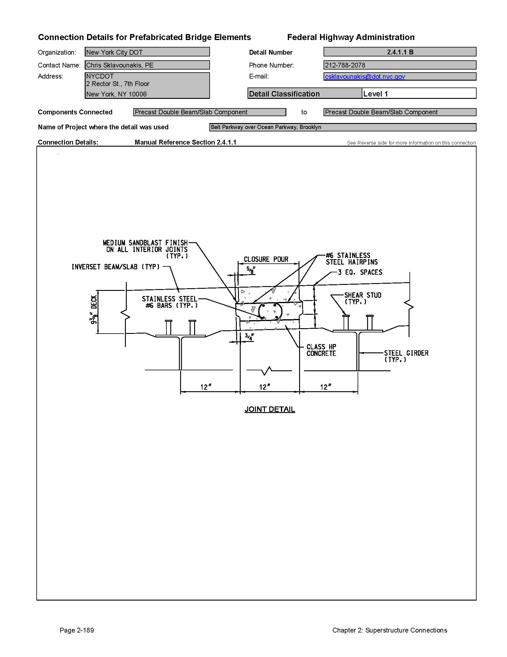
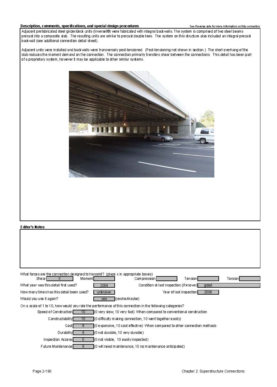
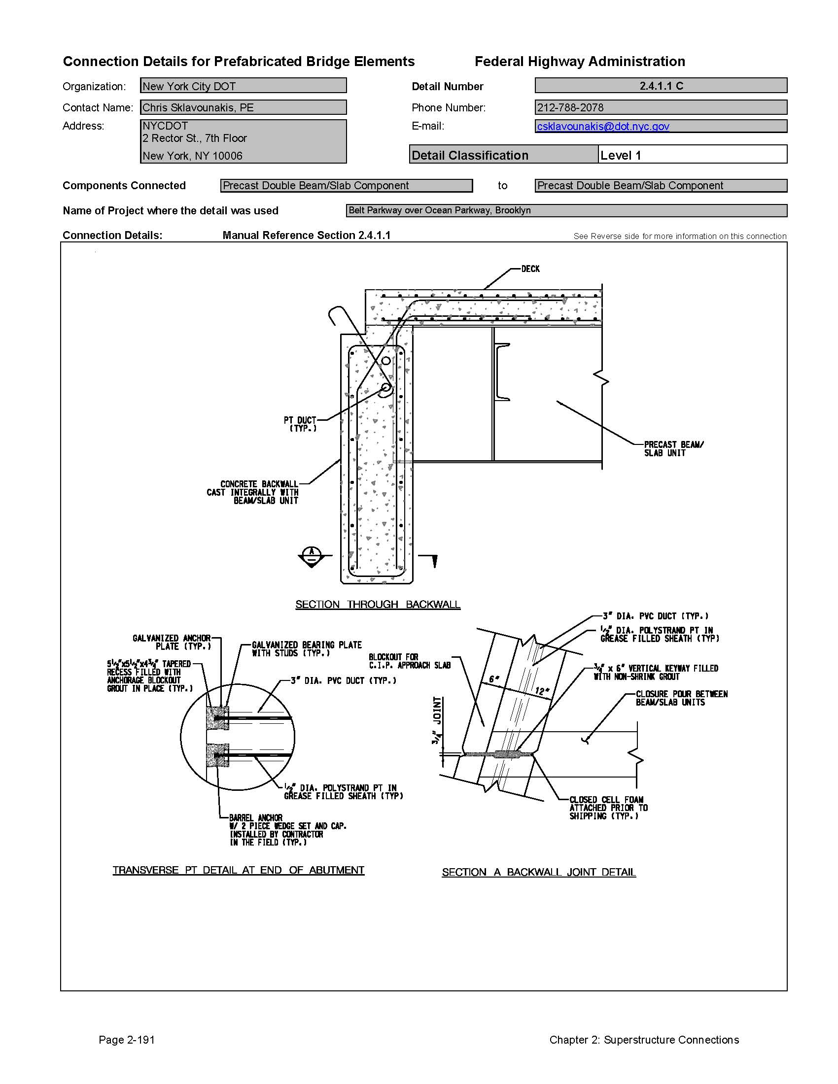
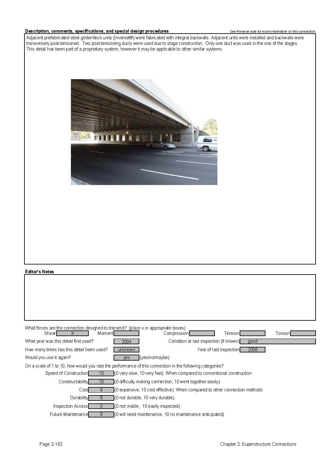
2.4.1.1 Transverse Connection Between Units
The inverset system is essentially a double tee unit that can be transported to the bridge site and erected quickly. The main connection to adjacent units is accomplished using bolted diaphragm plates. The overhangs of the units are normally kept small so that the connection at the deck level is essentially a shear connection that requires only a grouted keyway.
Several states have used this system. New York DOT has used it extensively to replace aging bridge superstructures and to increase vertical clearance at highway overpasses. There are several details used at the deck connection. The most common is a non-shrink grouted shear key to improve durability. Other details include small closure pours containing hooked reinforcing projecting from the edges of the deck units.
2.4.2 Large Precast Deck/Stringer Superstructure Systems for Bridges with Floorbeams
There are many large steel bridges in the United States that are constructed with either trusses or large girders connected with floorbeams. In most cases, another layer of framing called stringers spans between the floor beams. The stringers normally support the bridge deck. The process of replacing a deck on a floorbeam stringer bridge is cumbersome. If the floor beams are composite, it may not even be possible to replace the deck without closing the bridge, since removal of the deck would reduce the capacity of the floorbeam.
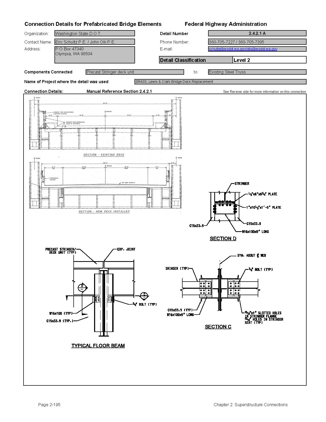
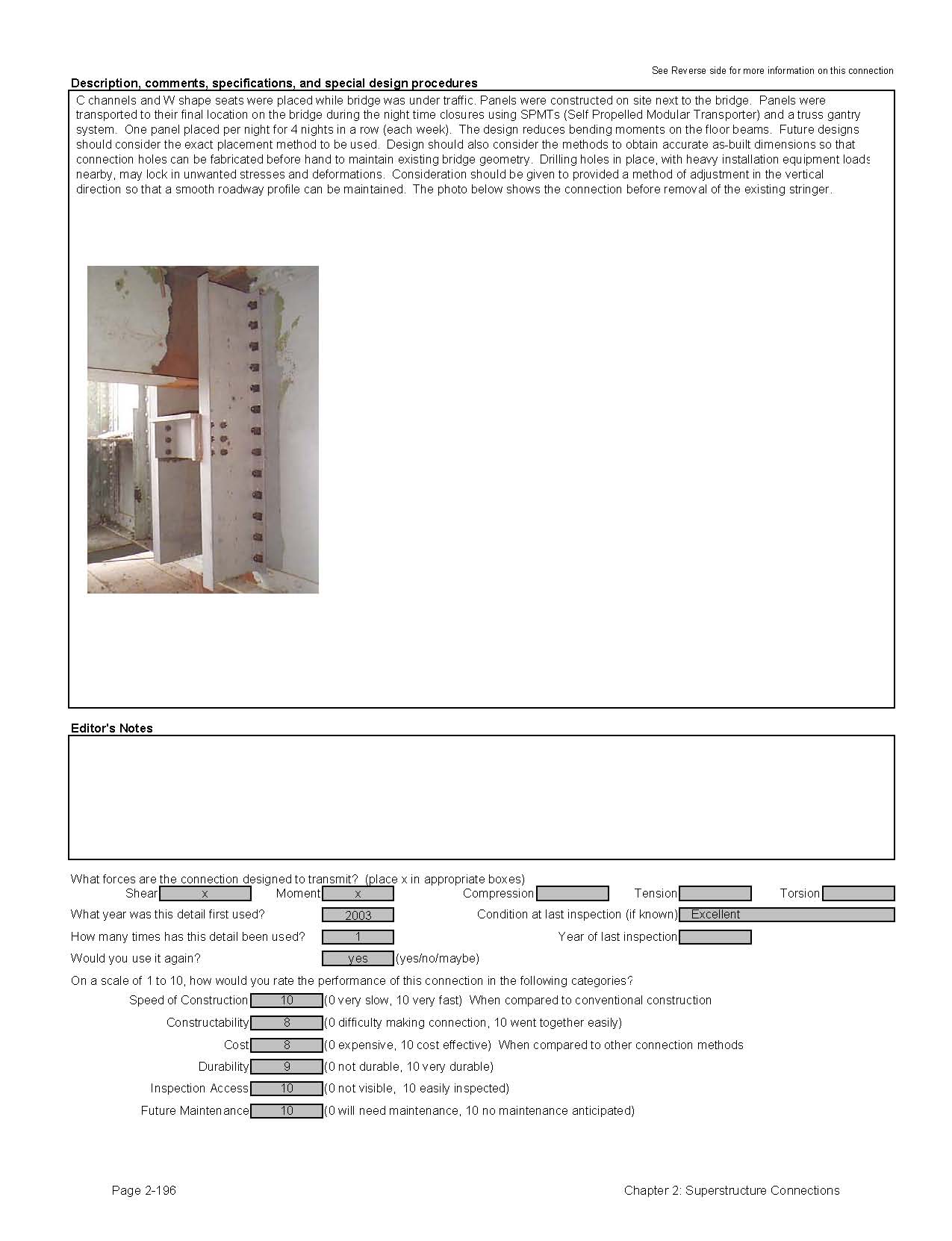
At least one state (Washington State DOT) has developed a system that can be used to replace the deck of a floorbeam stringer bridge with only nighttime closures. To expedite the process, the existing deck and stringers are replaced with a full-width unit that consists of the full-depth precast deck and all framing between the floorbeams.
This system was used effectively on the Lewis and Clark Bridge, which spans the Columbia River between Washington and Oregon. Designers reduced the number of stringers from six to two in order to reduce the bending moments in the floorbeams, which led to an increase in the load capacity of the bridge. This also reduced the number of connections in each panel.
Figure 2.4.2-1 depicts the bridge cross section before and after the project.
Figure 2.4.2-1 Lewis and Clark Bridge Details
(Courtesy of Washington DOT)
The re-arrangement of the stringer locations on the Lewis and Clark Bridge actually assisted in this operation since much of the framing work required at the new connection location could be completed before removal of the old bridge deck.
The construction of the deck of the Lewis and Clark Bridge was accomplished with a trailer-mounted gantry crane that was used to remove the portion of the deck between the floorbeams and set the new unit in one operation. This approach was complicated by the overhead framing of the bridge truss. The gantry system was designed to fit within the bridge opening and allowed the replacement of the deck stringer units in overnight operations. Figure 2.4.2-2 is a photo of the completed bridge, showing the limited height available for operation of the gantry system.
Figure 2.4.2-2 Lewis and Clark Bridge (Courtesy of Washington DOT)
2.4.2.1 Connection to Steel Floorbeams
The connection of a deck stringer system to the floorbeams is critical. The connection needs to clear the top flanges of the floorbeam and be seated properly.
The details presented are for one specific bridge; however, the system can be adapted to many other floorbeam stringer bridge spans.
2.4.3 Precast Concrete Arch Systems
Several precast manufacturers have developed precast concrete arch systems. These systems consist of strip arch segments placed side-byside to create the bridge span. Most systems are filled arches with granular backfill placed over the arch to complete the structure.
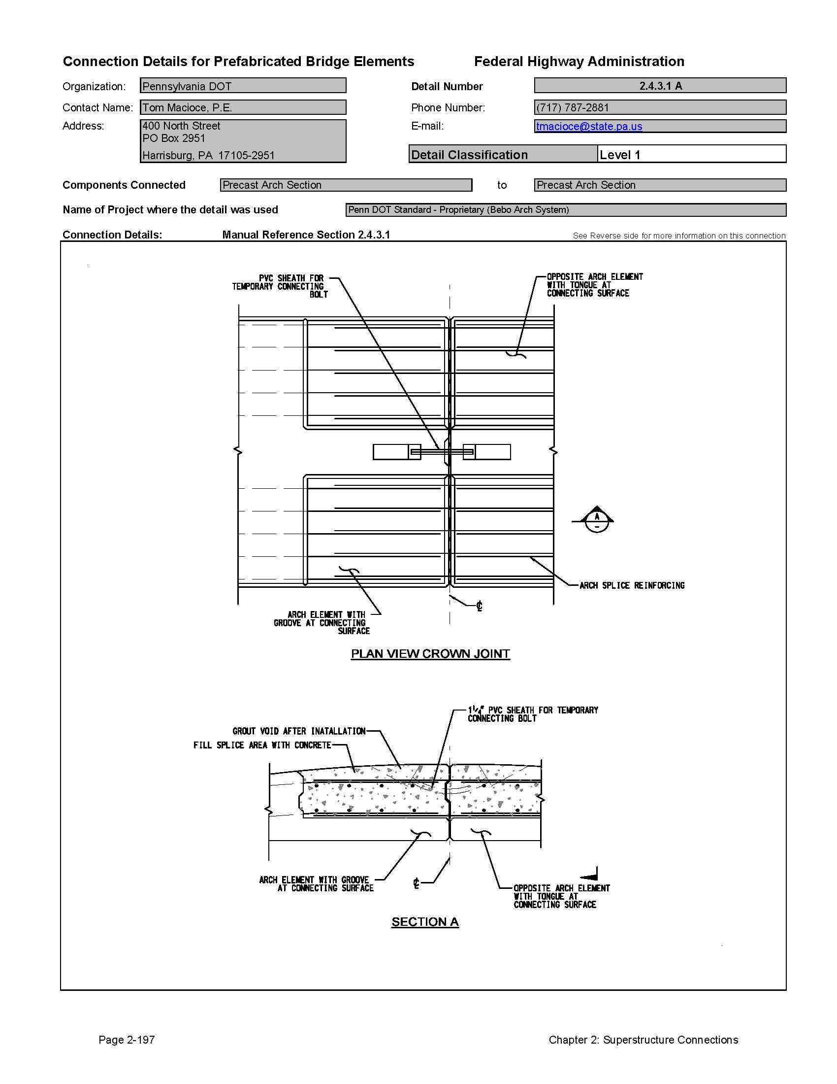
Most precast arch systems are complete span elements that include the vertical stems. Other systems consist of two or three precast arch elements connected in the field to complete the arch. Some of these systems are proprietary and others have been developed by state agencies.
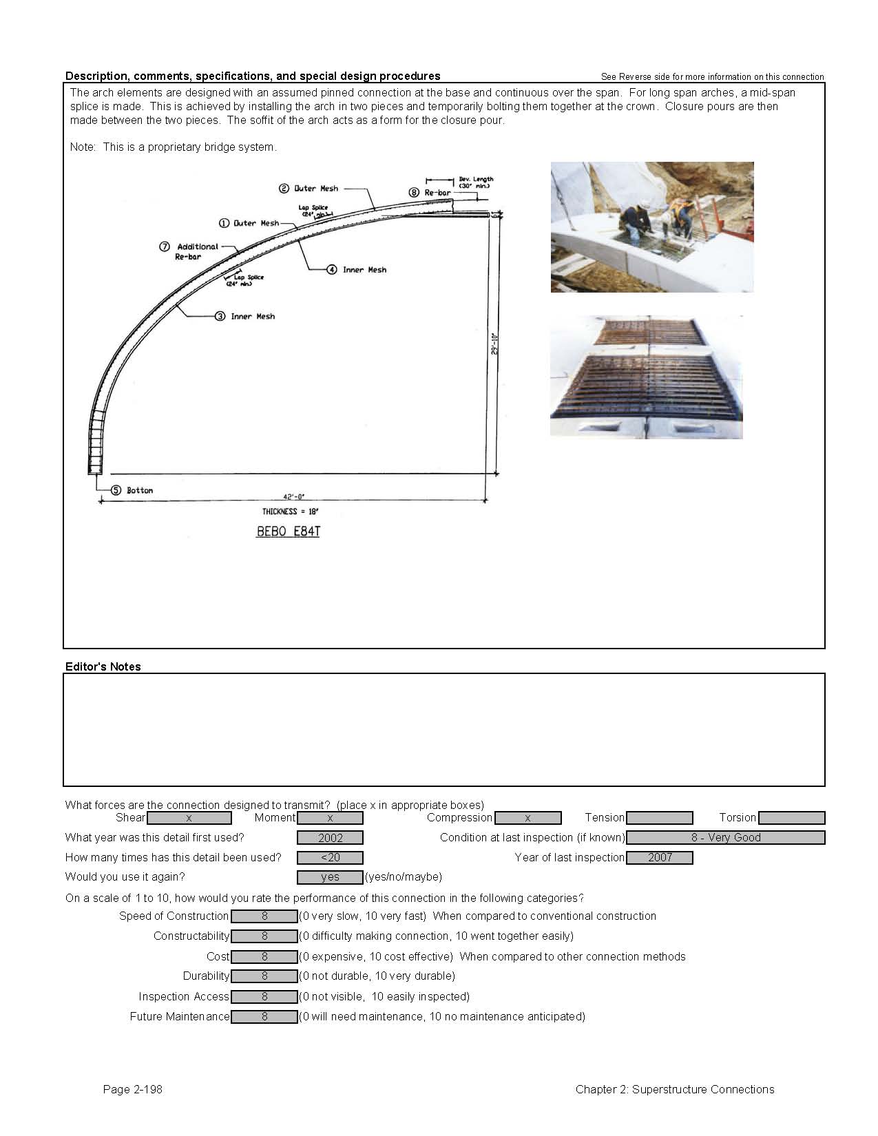
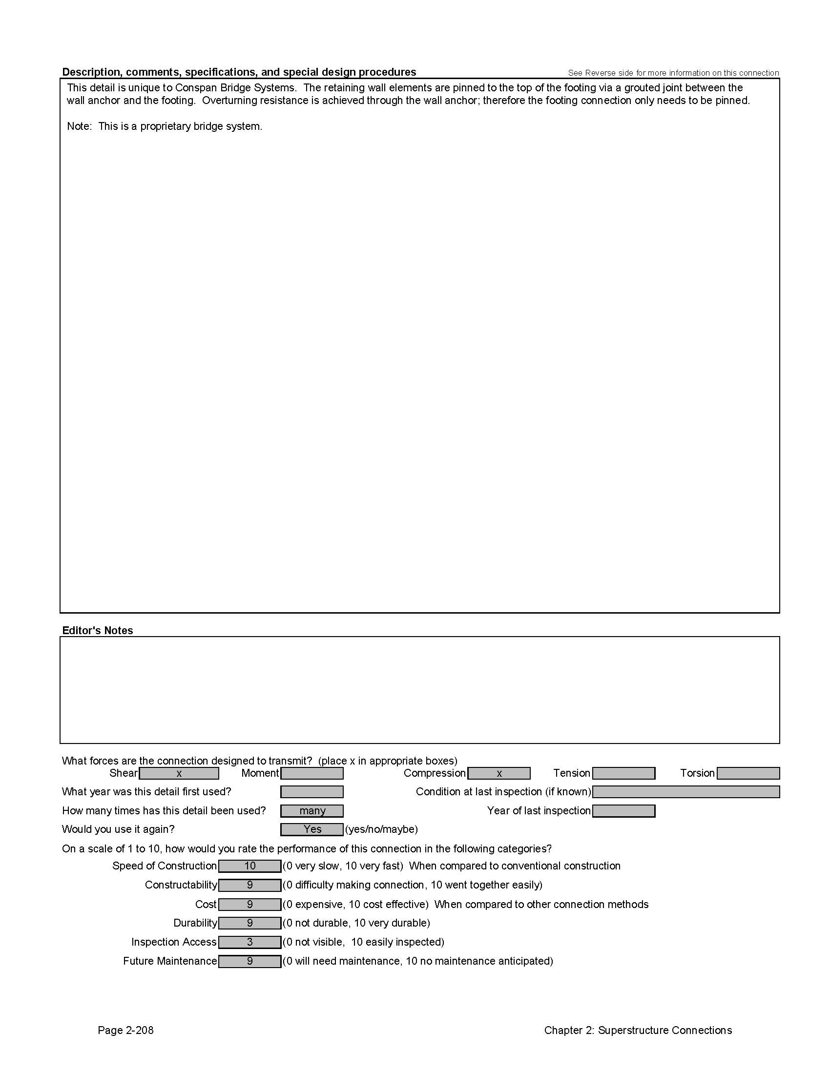
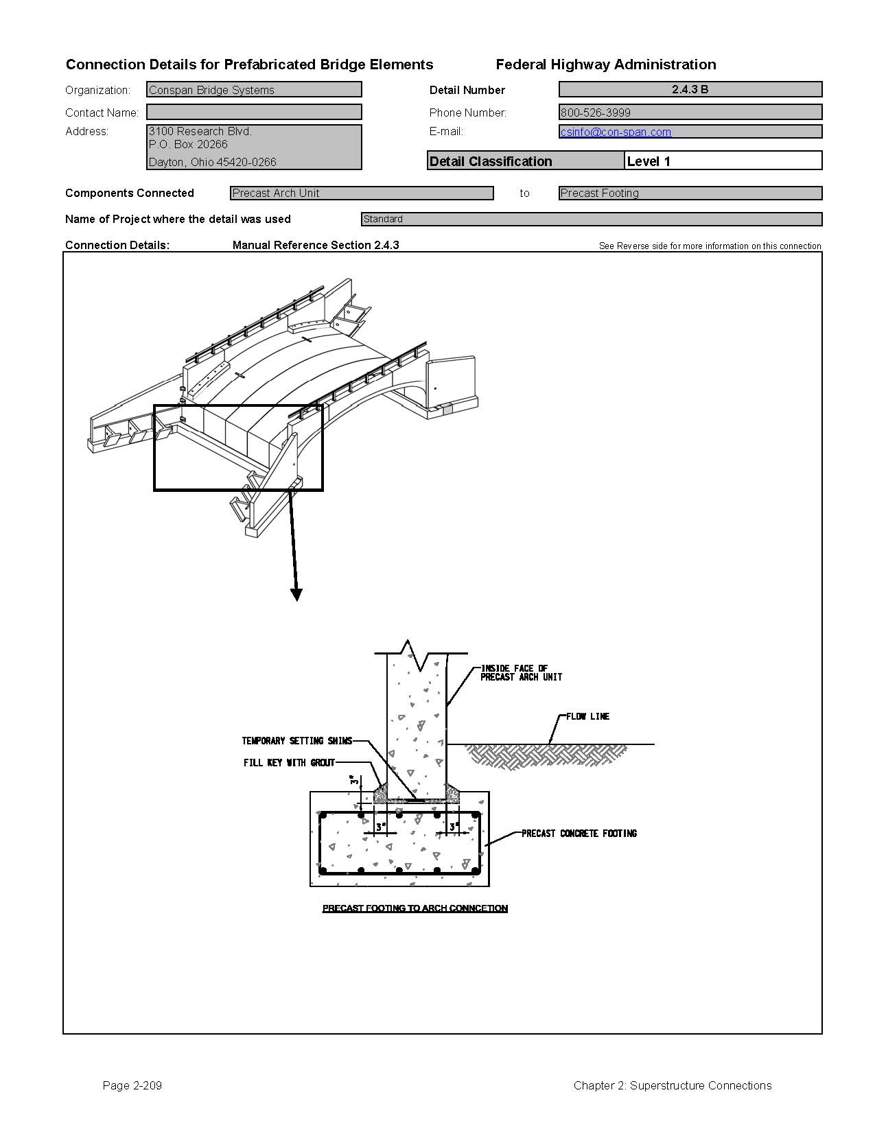
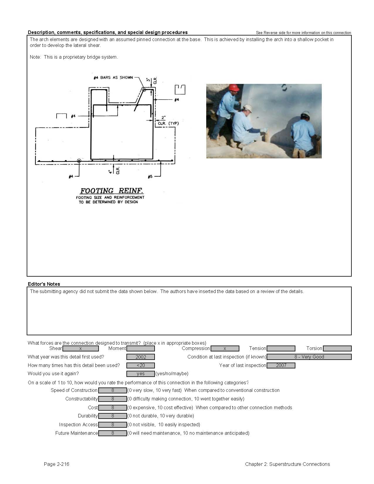
In most cases, the arches are designed as a two-hinge arch. The connection to the footings is designed as a pinned connection. The arch base is simply inserted into a keyway in the footing and grouted in place.
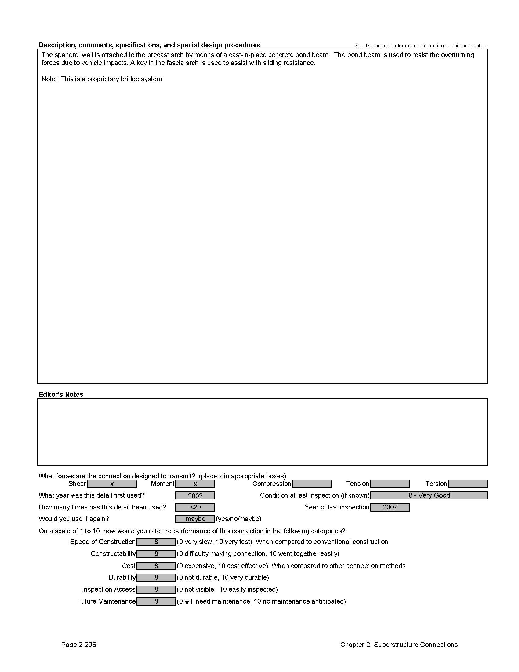
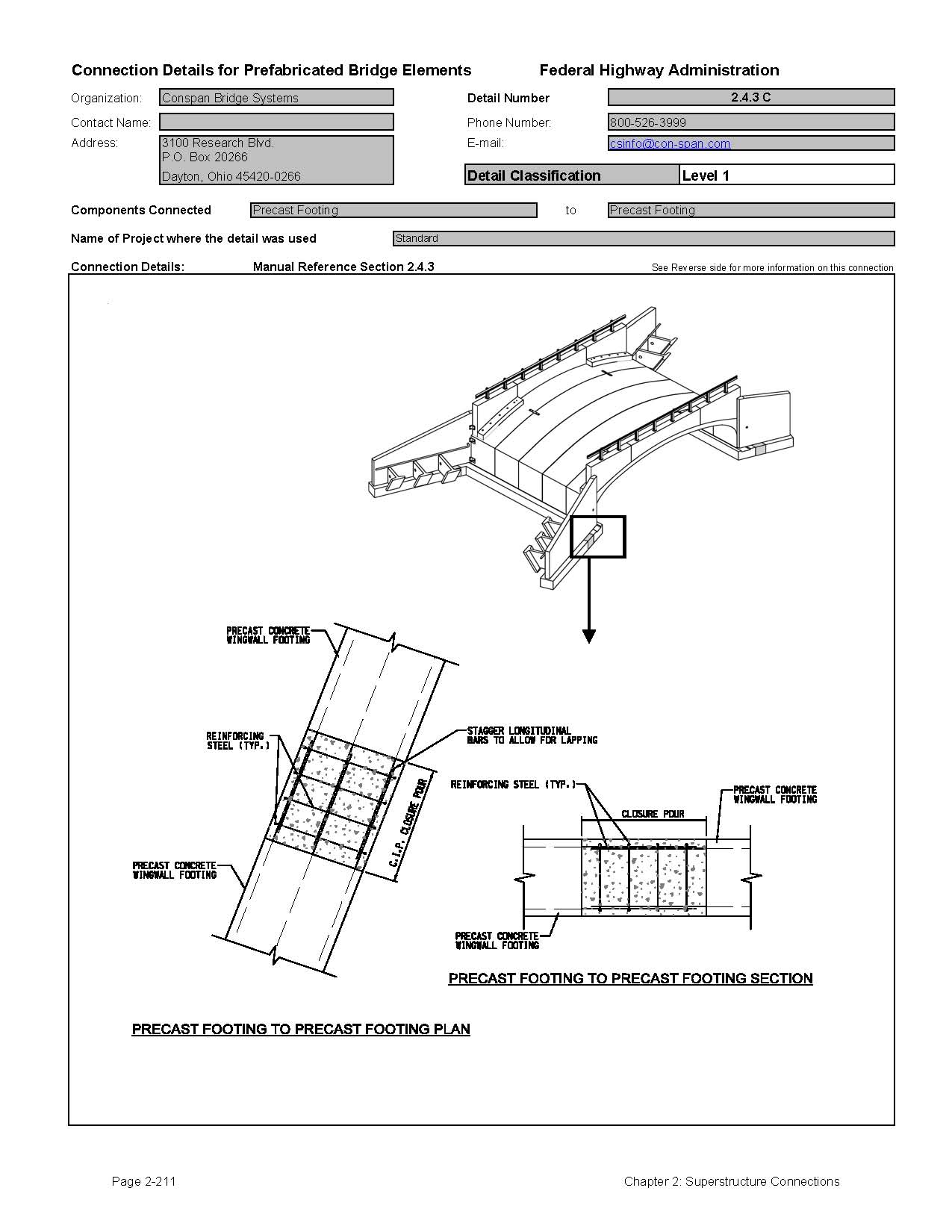
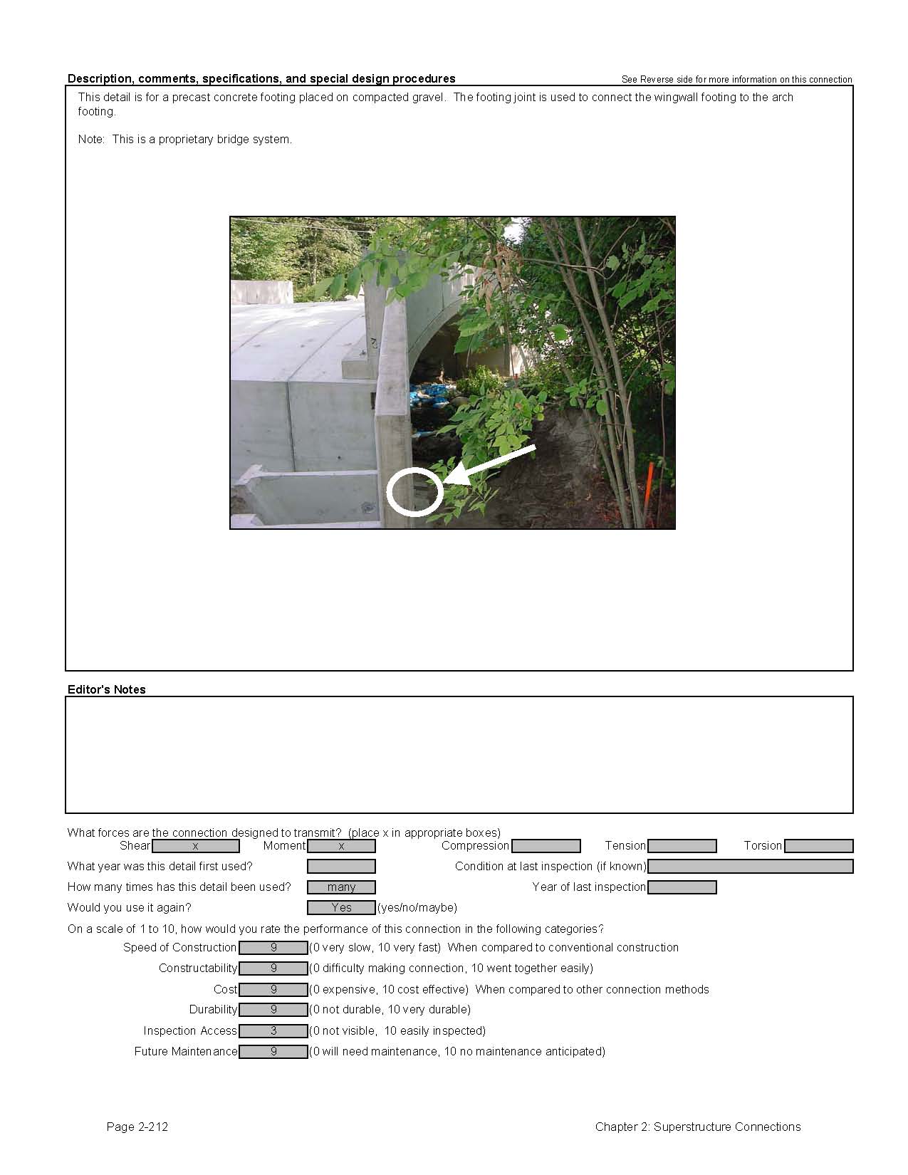
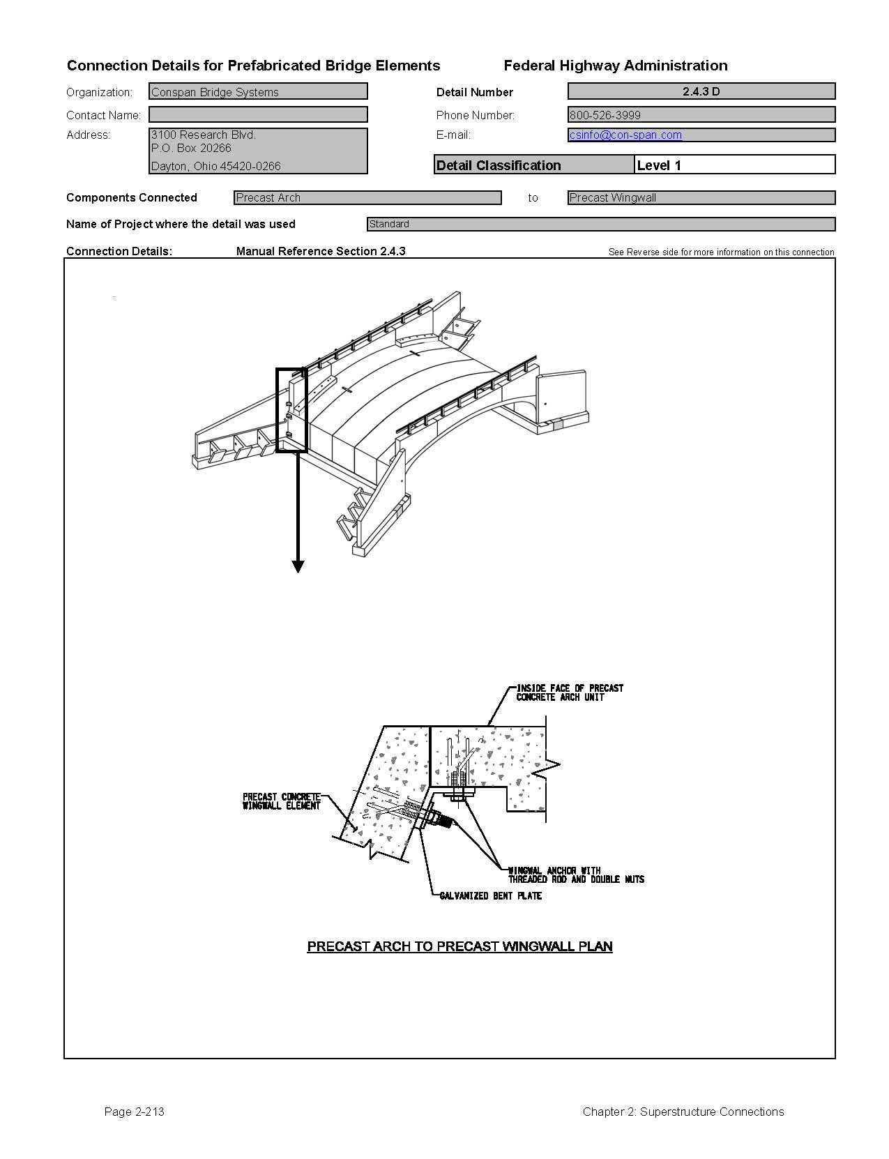
Figure 2.4.3-1 depicts a proprietary arch system call the Con/Span® Bridge System. This system, including the arch elements, the spandrel walls, the wingwalls and the footings, can be completely made with precast concrete elements. The connections shown in Figure 2.4.3-1 are described in the following sections.
Figure 2.4.3-1 Con/Span® Bridge System
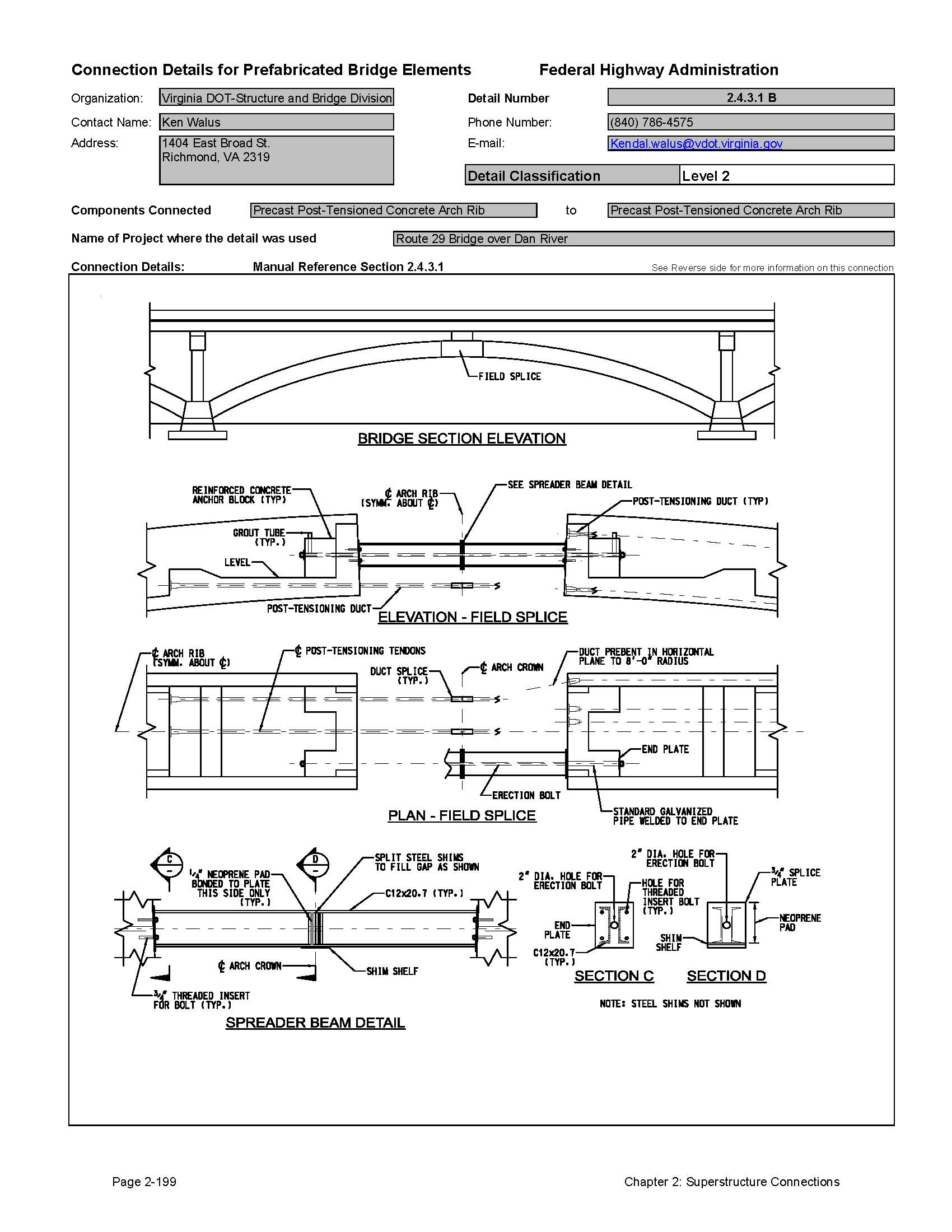
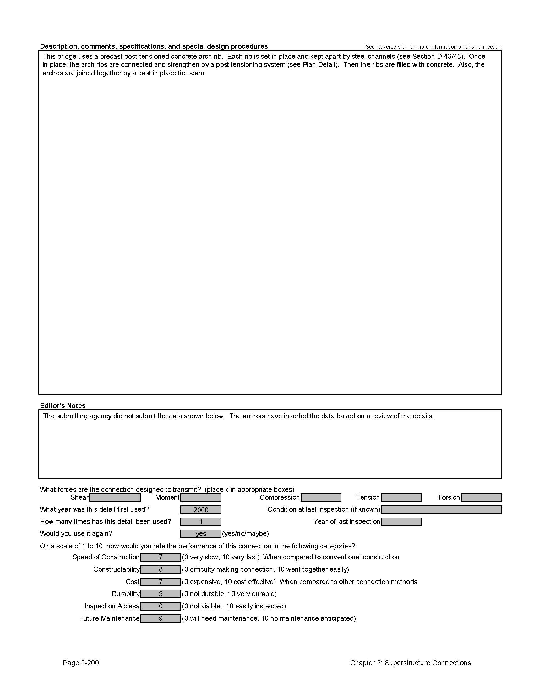
2.4.3.1 Connection Between Arch Elements
The State of Tennessee developed a precast arch system for a bridge on State Route 1 over Piney Creek. A similar connection has been developed for the Bebo® arch system. The arch segments are cast in two pieces. When erected, the two pieces form a three pin arch to support its self weight (pinned at the base and at the crest). The connection of the arch pieces was essentially a cast-in-place closure pour with lapped reinforcing. Once the connection is complete, the arch behaves as a two hinge arch for all other loads. This greatly reduced the amount of falsework typically required to erect a concrete arch bridge.
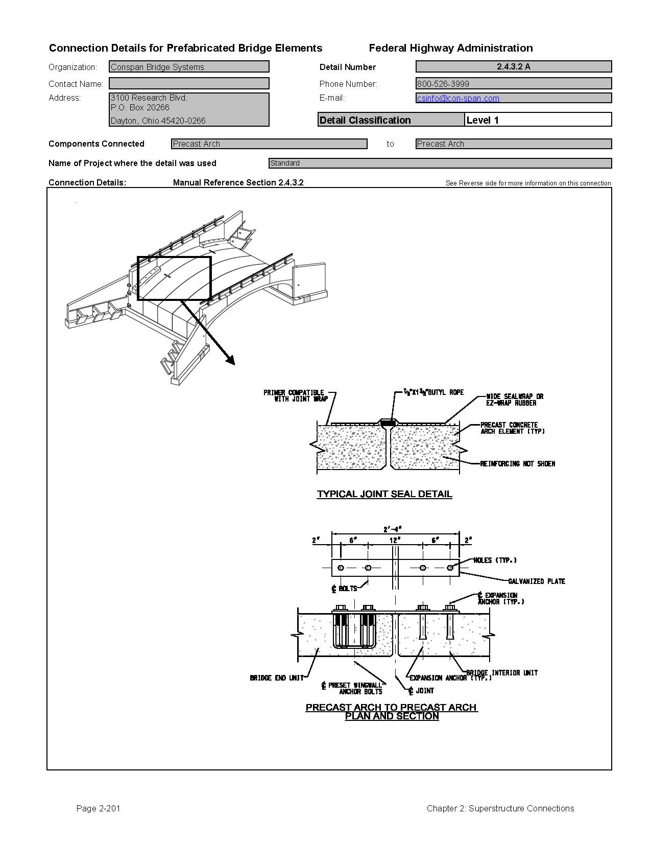
2.4.3.2 Connection Between Arch Segments
Most precast arch segments are simply butted together with no structural connection. These joints can are the joints that are shown parallel to the roadway in Figure 2.4.3-1. This lack of connection is accounted for in the arch design. A waterproofing strip is placed over the opening to prevent backfill soils from falling through the joints. On one system, there is a structural connection between the fascia arch and the interior arches. The lateral forces acting on the spandrel walls impart transverse overturning forces on the fascia arch. A simple tension connection on the top of the arches ties several arch elements together to increase the overturning resistance of the arch structure.
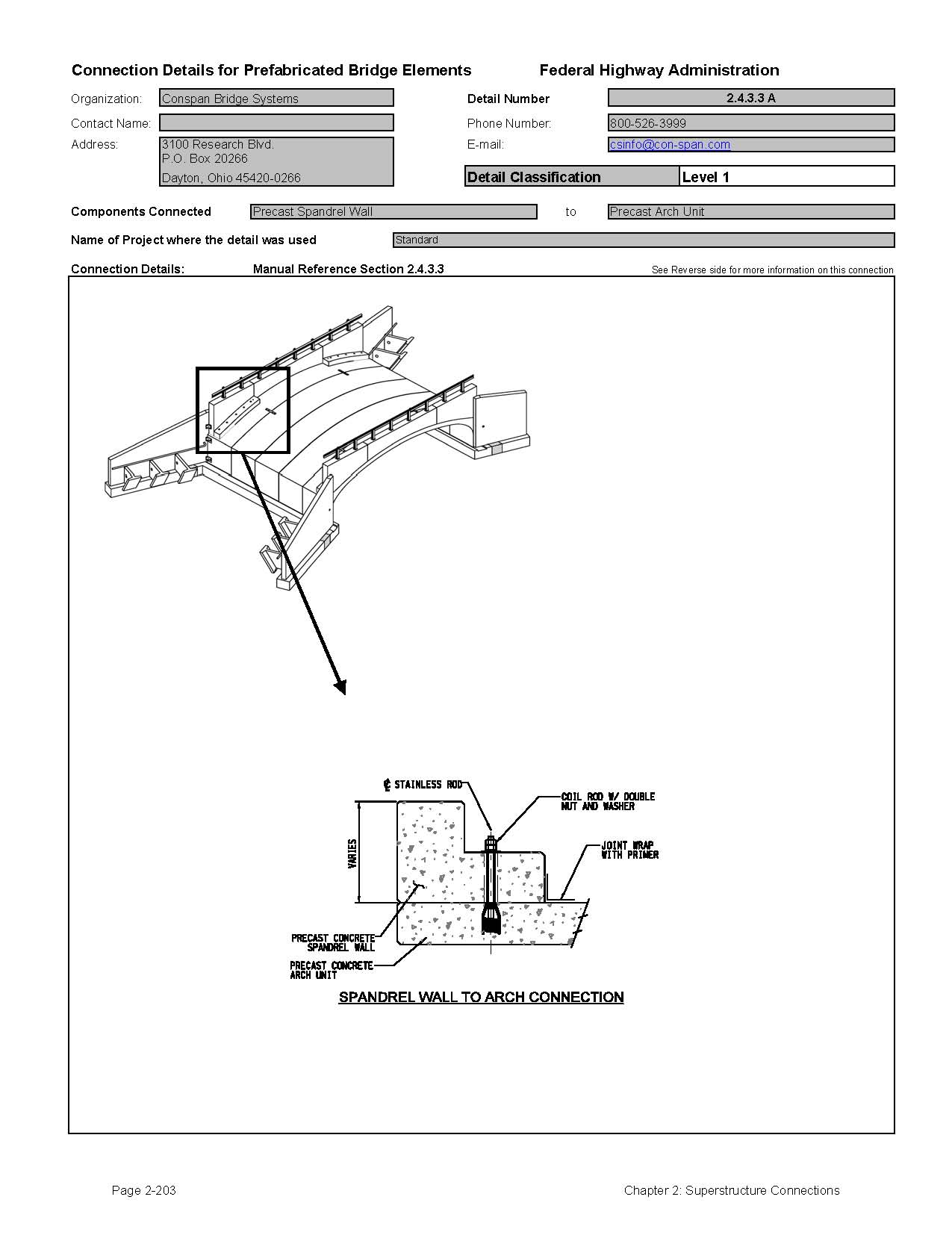
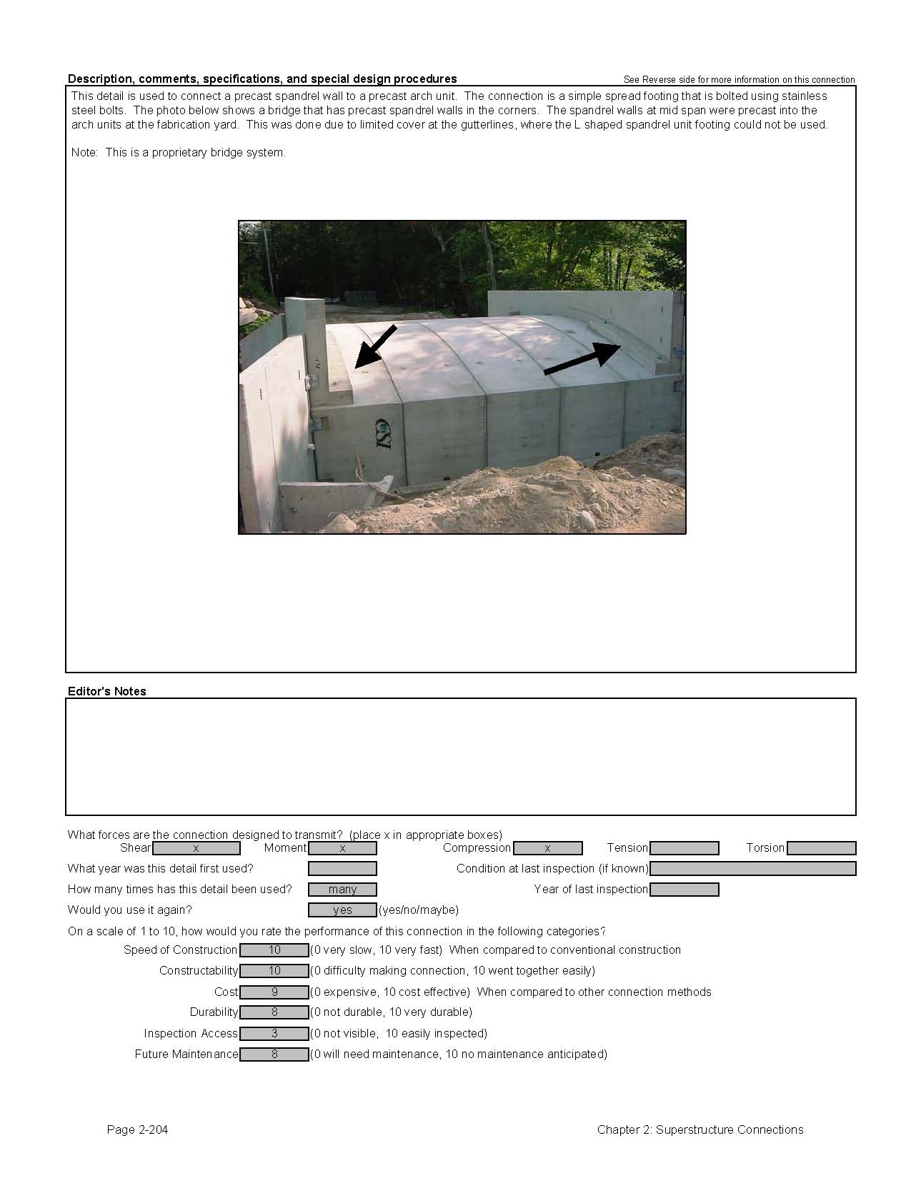
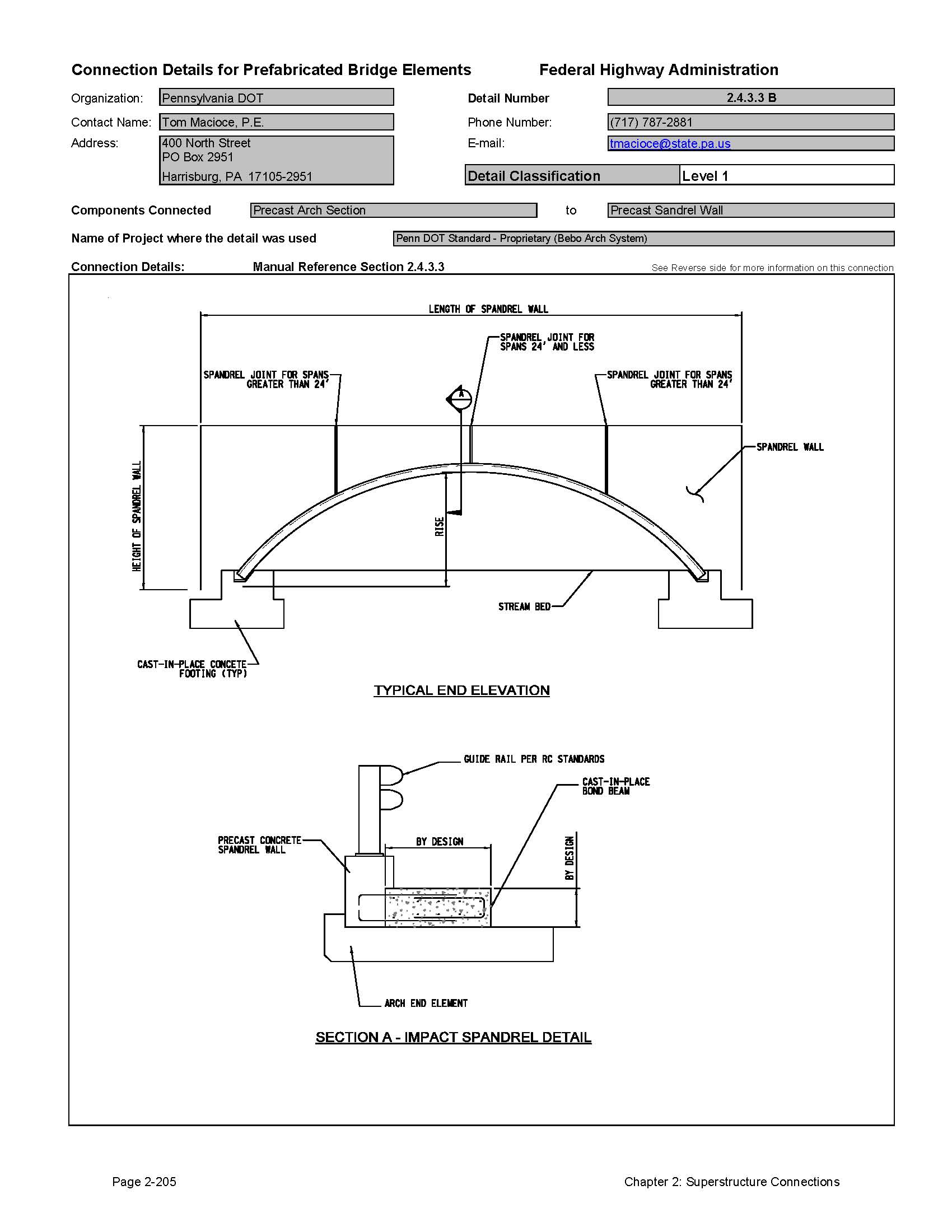
2.4.3.3 Connection of Spandrel Walls
Most arch systems have fill placed over them, requiring the use of spandrel walls to contain the fill soils. The spandrel walls can either be precast onto the fascia arch in the fabrication plant, or precast for installation in the field. The Con/Span® Bridge System has precast fascia panels that are bolted to the fascia arch element.
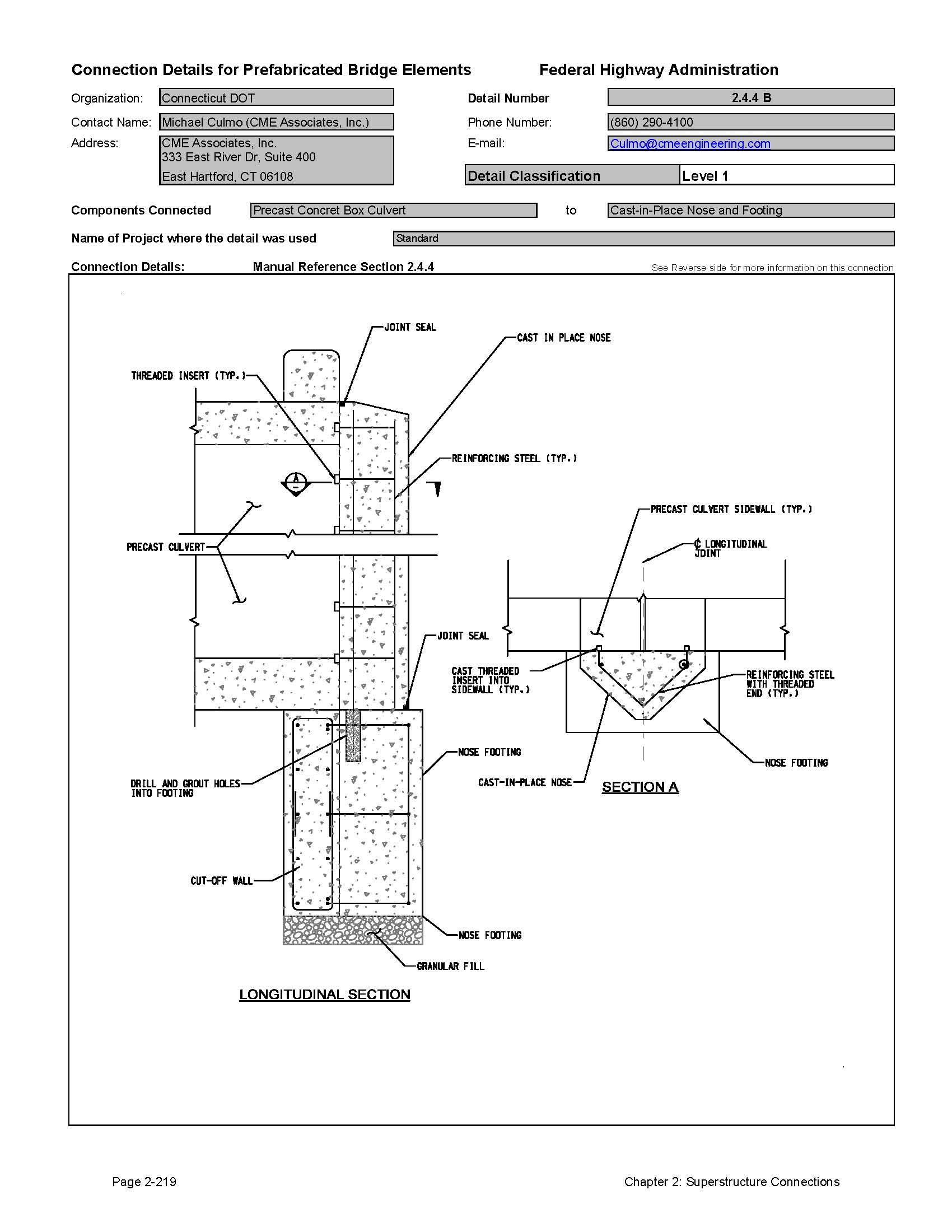
2.4.4 Precast Concrete Box Culverts
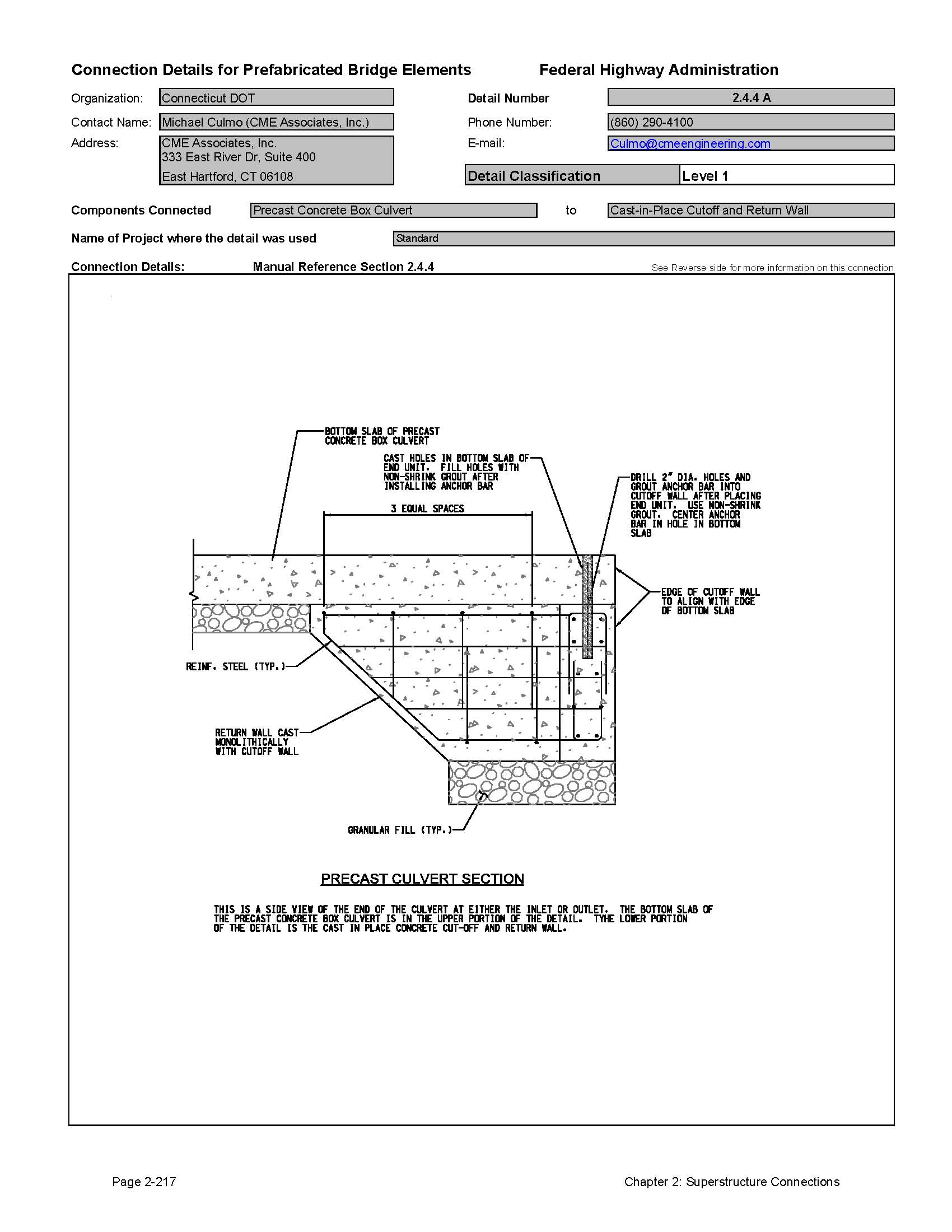
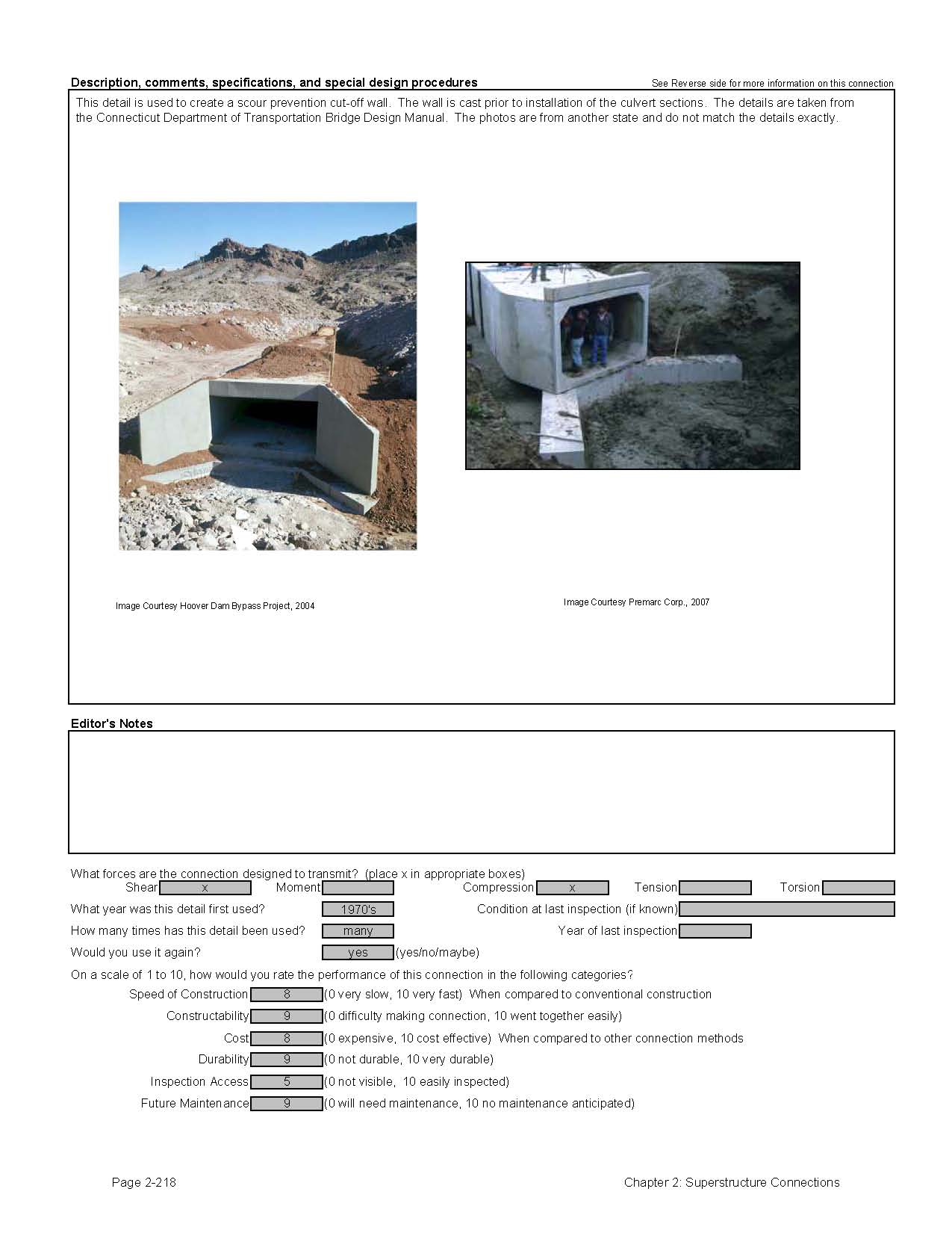
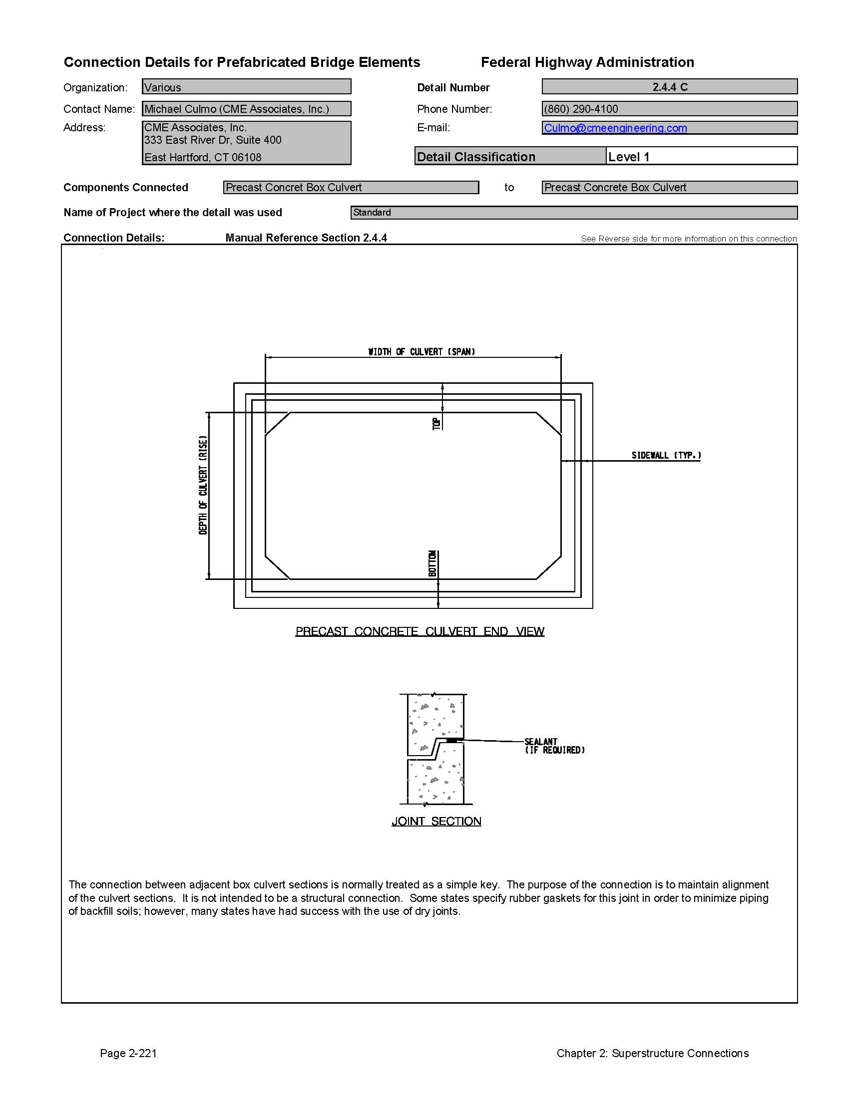
Many state agencies have developed standard details for precast concrete box culvert systems. The American Society of Testing and Materials (ASTM) Specification C1433 entitled "Standard Specification for Manufacture of Precast Reinforced Concrete Box Culverts, Storm Drains, and Sewers" [52] can be used to design and detail these systems. This ASTM specification is for single cell box culverts. For multi-cell box culverts, designers typically butt single cell units side-by-side.
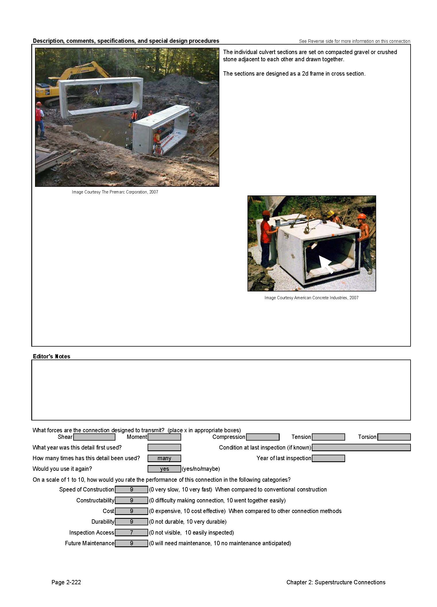
The use of precast concrete box culverts has become commonplace across the country; therefore, significant details are not presented in this Manual. Typical connections include the installation of headwalls, and nosings. The connection between boxes is typically a nested shear key that is not grouted, similar to the connection used on reinforced concrete drainage pipe. Some states require rubber gaskets in the keys. Several details are presented in this Manual for information. Readers are urged to contact state highway agencies for more information on the details used in their region.
2.4.5 Grade Control and Tolerances
Grade control and tolerances are critical for most systems presented in this section. This is especially true for large prefabricated deck stringer systems. Detailed surveys of the existing bridge framing are required to ensure proper fit-up of the systems. Designers should also detail minor adjustability to accommodate fabrication tolerances. This is usually accomplished through the use of variable thickness shims.
Grade control and tolerances are not as critical for large precast concrete arch systems and box culverts; however, designers should specify the appropriate casting tolerances to ensure proper fit-up of the elements in the field. The setting of tolerances on proprietary systems is usually left up to the fabricator. ASTM C1433 includes guidance on fabrication of box culverts.
2.4.6 Evaluation of Performance and Long Term Durability of Modular Prefabricated Superstructure Systems
With the exception of precast concrete box culverts, the systems presented in this section are relatively new to the bridge industry. The modular precast deck stringer systems should provide improved resistance to the elements because the systems are constructed with fewer joints and in a controlled environment using high quality concretes. The inverset system uses a casting technique that has the final top surface of the deck cast against a form. It is believed that this process will lead to a denser top surface since the bleed water will exit the slab through the bottom during curing, which in theory will lead to a less pervious surface.
Precast concrete arch systems and box culverts are produced with high quality concrete in a controlled environment, which should result in higher quality products with longer service lives.
2.4.7 Estimated Construction Time for Connections
The times required for construction depend on a number of factors including site access, traffic control, weather, crane locations and proximity to storage areas. Nonetheless, it is possible to make reasonable estimates of the minimum required construction time for the various systems discussed in this section.
Table 2.4.7-1 provides approximate installation times for the various systems included in this section:
| System | Minimum Installation Time | Comments |
|---|---|---|
| Precast Deck/Slab Systems | 1 Day | Can also be installed during an overnight closure operation |
| Larger Precast Deck stringer systems | 1 Day | Can also be installed during multiple overnight closure operations |
| Precast Concrete Arch Systems | 1-2 Days | A small single-span bridge can be erected in one day after preparation of the site. This does not include the time for backfilling. Total construction can be completed in less than 2 weeks |
| Precast Concrete Box Culvert | 1 Day | Does not include time for site preparation or backfilling |
2.4.8 Recommendations for Improvements to Current Practices
Each system presented in this section is unique. The standard details for most of these systems have been thoroughly tested and demonstrated on numerous projects; therefore, the authors have no recommendations for improvements.
2.4.9 Connection Detail Data Sheets for Modular Prefabricated Superstructure Systems
The following pages contain data sheets for the various modular prefabricated superstructure systems. Some systems were obtained from manufacturers and industry groups. This information was primarily gathered from agencies that have developed and used the systems. Most data in the sheets were provided by the owner agency; the authors added text when an agency did not supply all requested information. The owner agencies also provide a comparative classification rating.
Each connection detail data sheet is presented in a two-page format. Users of this Manual can simply remove and copy a data sheet for use in developing a system for a particular project. These sheets are meant to give users a basic understanding of each connection that can be used during the type study phase of a project. The data sheets are not meant to be comprehensive, but do convey the component make-up of the detail, how it is meant to function, and provide some background on its field application. Users will need to investigate each connection further, consider site-specific conditions, and apply sound engineering judgment during design.
The key information provided for each connection is as follows:
- Name of the organization that supplied the detail
- Contact person at the organization
- Detail Classification Level
- Level 1
This is the highest classification level that is generally assigned to connections that have either been used on multiple projects or have become standard practice by at least one owner agency. It typically represents details that are practical to build and will perform adequately. - Level 2
This classification is for details that have been used only once and were found to be practical to build and have performed adequately. - Level 3
This classification is for details that are either experimental or conceptual. Details are included in this Manual that have been researched in laboratories, but to the knowledge of the authors, have not been put into practical use on a bridge. Also included in this classification are conceptual details that have not been studied in the laboratory, but are thought to be practical and useful.
- Level 1
- Components connected
- Name of project where the detail was used
- Manual Reference Section
- The section(s) of this Manual applicable to the particular detail shown.
- Connection Details
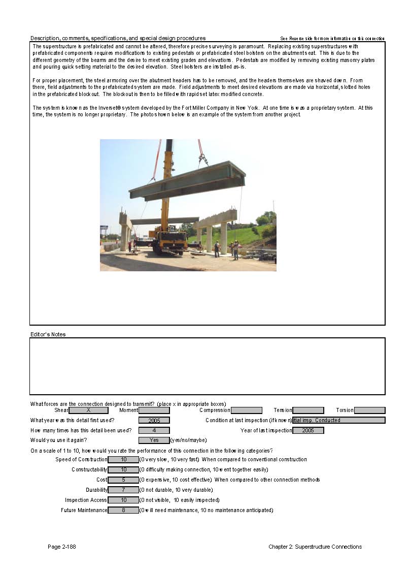
- Description, comments, specifications and special design procedures
- Forces that the connection is designed to transmit
- Information on the use of the connection (including inspection ratings)
- A performance evaluation of the connection rated by the submitting agency
Click images below to enlarge
Detail 2.4.1.1A

Detail 2.4.1.1B
Detail 2.4.1.1C
Detail 2.4.1.1D

Detail 2.4.2.1A
Detail 2.4.3.1A
Detail 2.4.3.1B
Detail 2.4.3.2A

Detail 2.4.3.3A
Detail 2.4.3.3B
Detail 2.4.3A
Detail 2.4.3B

Detail 2.4.3C
Detail 2.4.3D

Detail 2.4.3E

Detail 2.4.4A
Detail 2.4.4B
Detail 2.4.4C
2.5 Connections between Superstructures and Substructures
This section focuses on connections between superstructure systems and substructures. In most cases, agencies place structural bearings at these connections. However, designers are increasingly specifying integral connections. This section will cover both types of connections and how each relates to accelerated bridge construction.
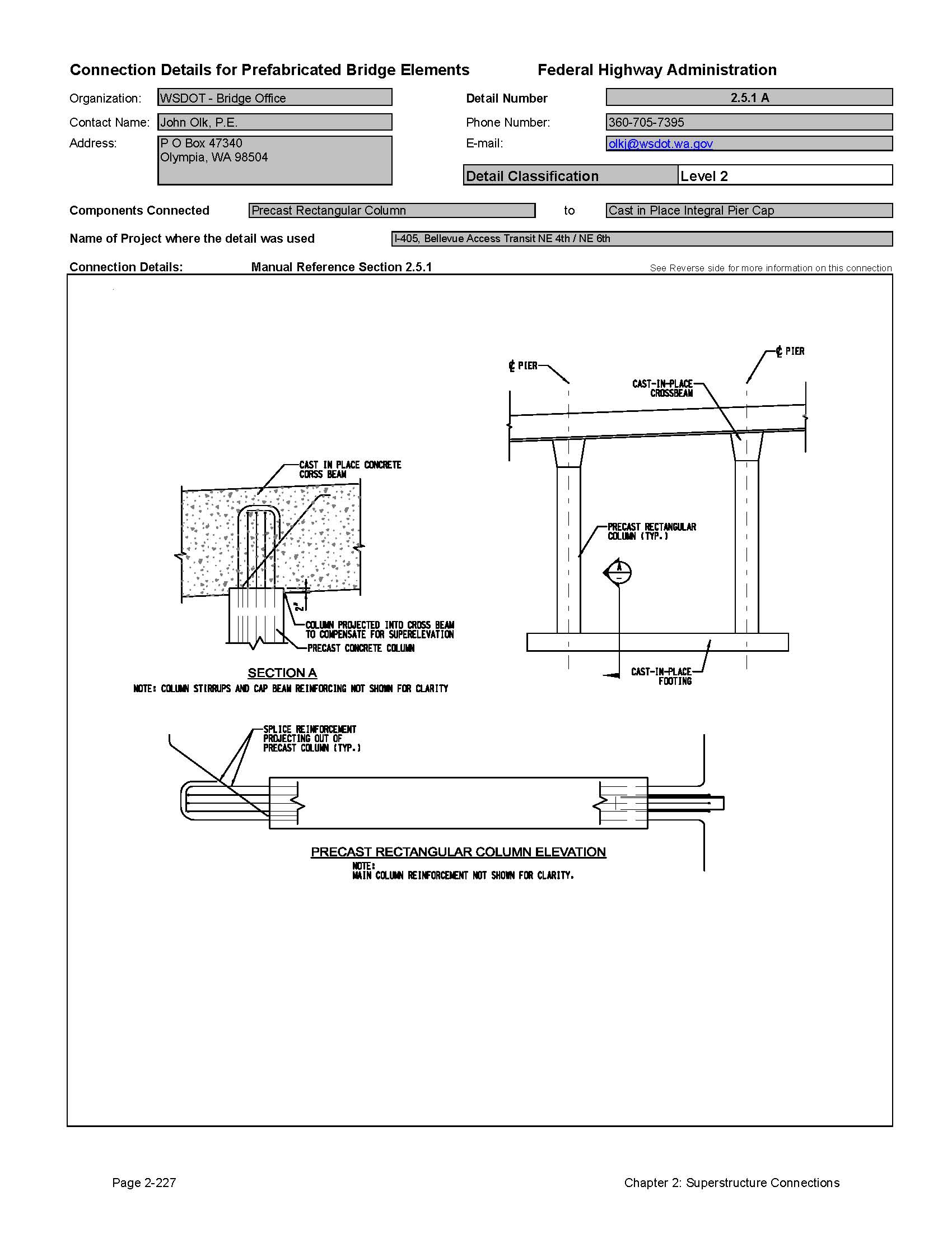
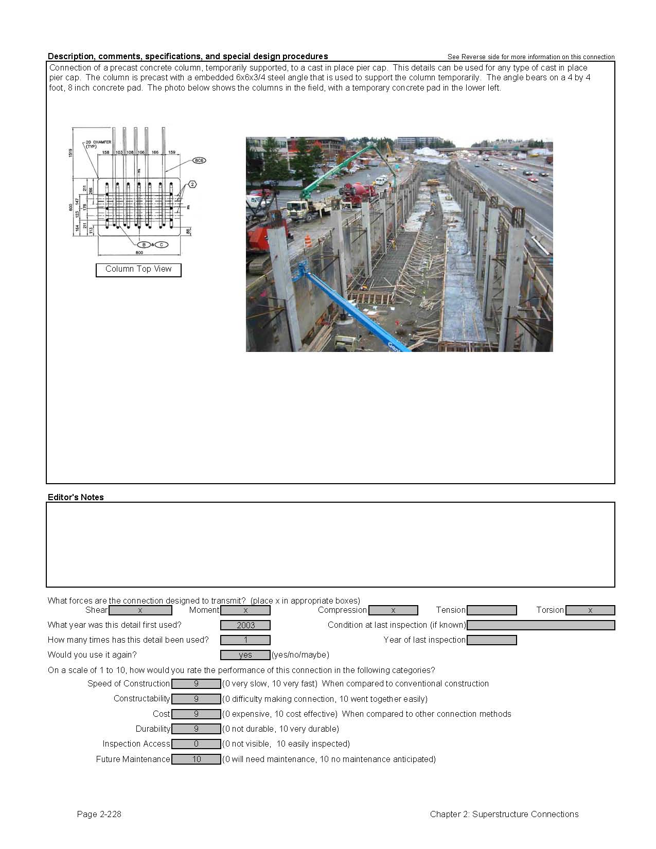
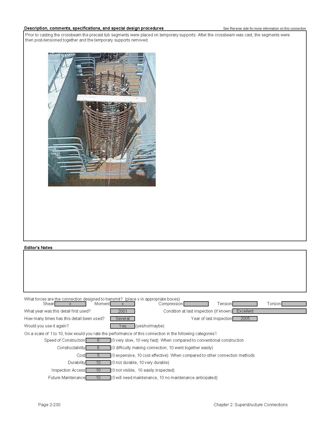
2.5.1 Integral Pier Caps
Several states have built bridges with integral pier caps. Integral piers are common on the west coast due to the high seismic requirements. In many cases, the superstructures are constructed with cast-in-place concrete; however, the connection can also be made using precast concrete in either the pier columns or the superstructure elements.
This connection is often very complicated and congested. There are also tight controls over tolerances and grades. For these reasons, the most common form of connection is a cast-in-place concrete closure pour. Reinforcing is typically extended from the precast concrete elements to form the connection.
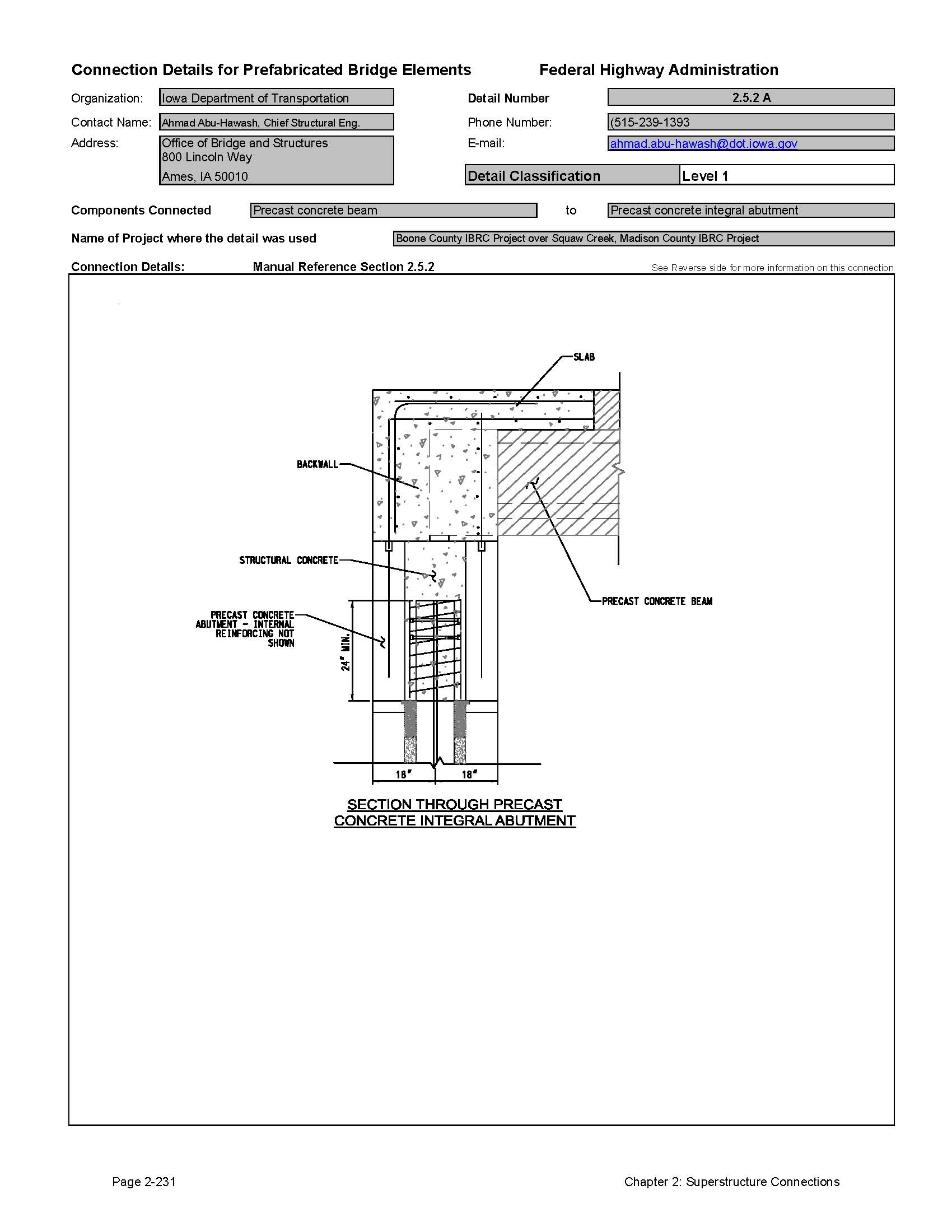
2.5.2 Integral Abutments
Similar to integral pier connections, integral abutment connections are often complicated and congested. Cast-in-place closure pours are the common form of connection used for integral abutments.
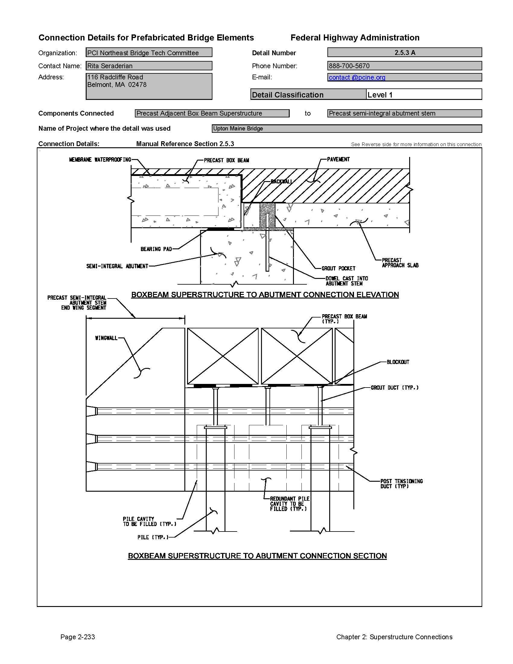
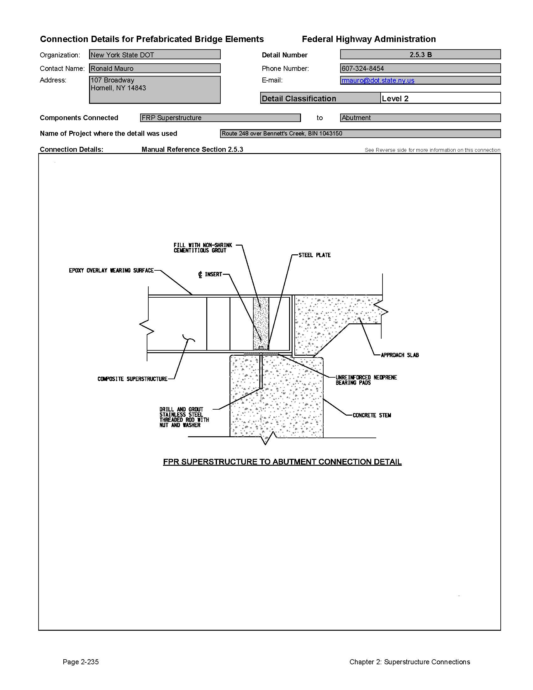
2.5.3 Semi-Integral Abutments
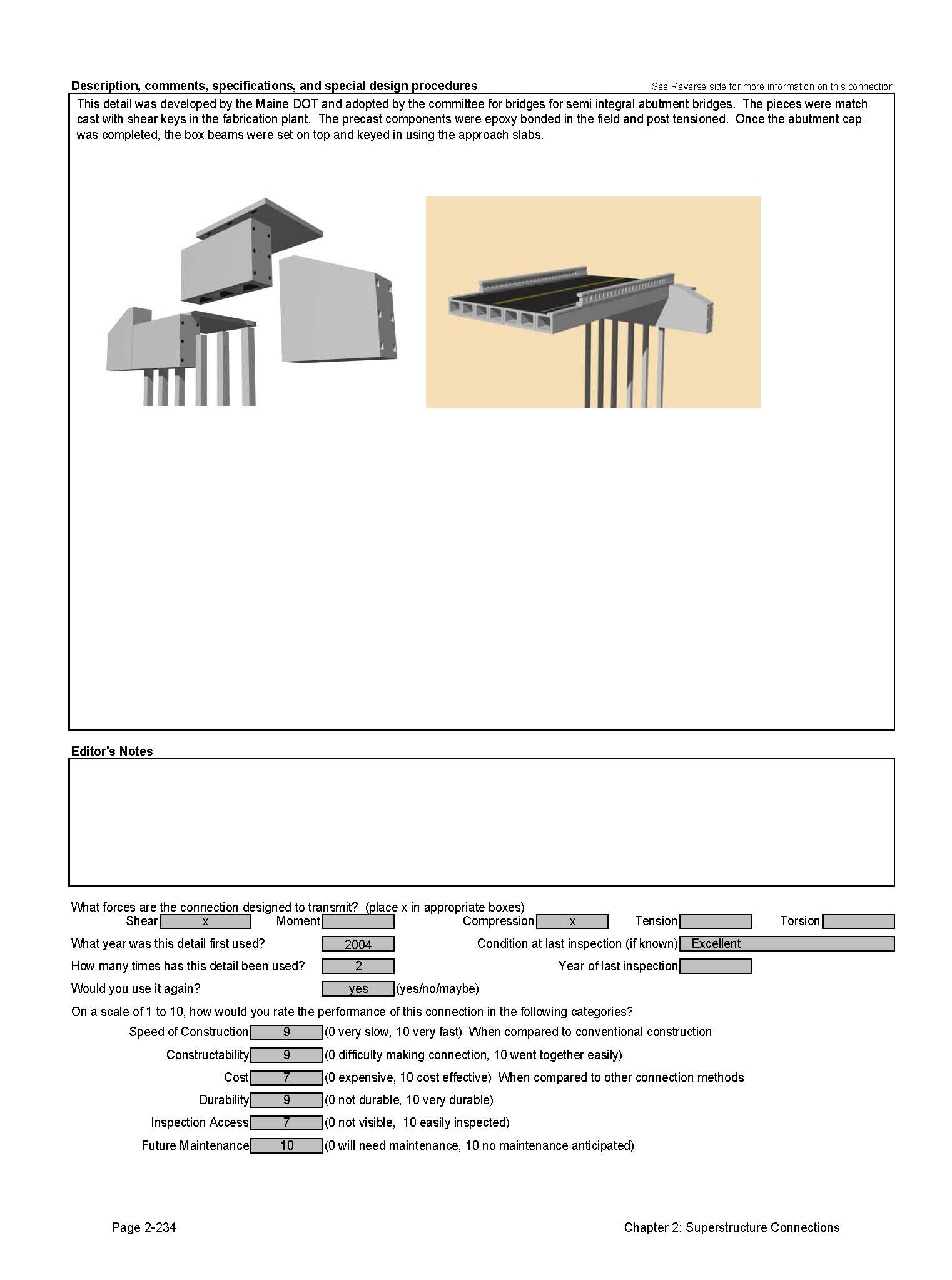
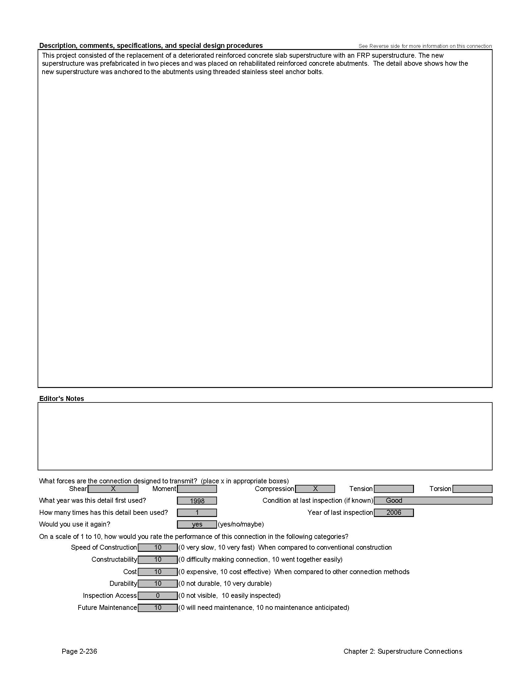
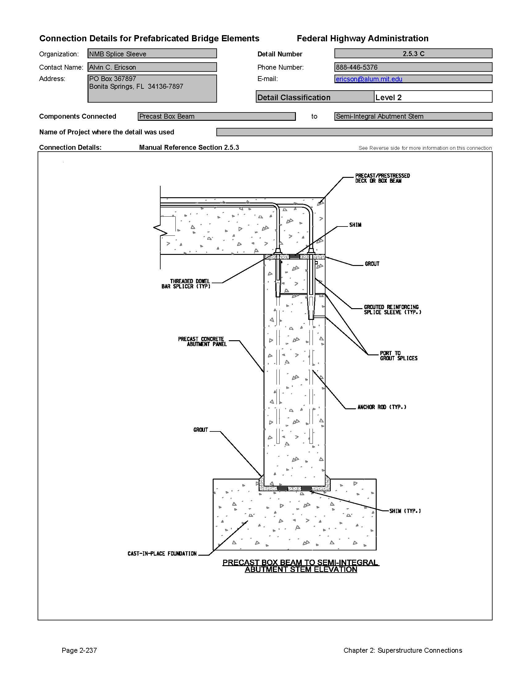
Semi-integral abutment connections are similar to integral abutment connections except they are not designed for moment transfer between the substructure and the superstructure. Instead, the connection transfers horizontal shear only (in both directions). These pinned connections can be detailed with anchor rods or simply by keying the superstructure to the substructure. The lack of a moment connection allows for a simpler connection that can be made with little or no site-cast concrete. The Maine DOT has developed a connection that uses precast prestressed concrete adjacent box beams keyed into the abutment seat. The beams are keyed in place by side blocks in the abutment and a precast approach slab in the rear of the abutment. This system does not require anchor bolts, allowing for a very fast connection.
2.5.4 Structural Bearings
Most bridges built in the United States employ structural bearings between the superstructure and substructure. This connection is usually not the critical path in the construction of a prefabricated bridge.
No bearing details are included in this Manual because each state agency has standard details for bearings. The detailing of bearing connections can be elaborate. Designers should make every attempt to simplify the design of bearings on prefabricated construction projects so that the connections can be made quickly.
2.5.5 Grade Control and Tolerances
The connection between the substructure and the superstructure is a location that lends itself to grade control and tolerance adjustments. This connection is often a cast-in-place concrete pour; therefore, there typically is room for a certain amount of adjustment.
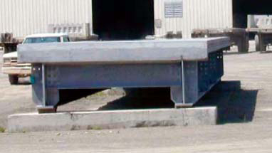
Structural bearings are another location where adjustment can be accommodated. Designers should detail bearing connections that allow for adjustment. One approach is to eliminate anchor bolts at the bearings. Another method to provide lateral restraint is the use of concrete shear keys cast between the beams. Figure 2.5.5-1 shows a seismic shear key for a precast pier cap. By eliminating anchor bolts, the contractor can adjust the layout of the superstructure on the substructure. AASHTO and the National Steel Bridge Alliance (NSBA) have published a document entitled "Steel Bridge Bearing Design and Detailing Guide" [45]. This document, available at the NSBA website and the AASHTO internet bookstore, has more information on anchoring bridge superstructures.
Figure 2.5.5-1 Seismic Shear Key
2.5.6 Evaluation of Performance and Long-Term Durability of Superstructure to Substructure Connections
Most connections listed in this section include the use of cast-in-place concrete. These connections have been used for years on conventional integral abutments and integral pier projects. The details have been adapted for prefabricated bridge construction.
The use of integral connections eliminates bridge deck joints, which are the primary sites of structural deterioration. Cast-in-place closure pours require more time than some connections; however, the durability of an integral connection is normally worth the extra construction time.
2.5.7 Estimated Construction Time for Connections
The times required for construction depend on a number of factors including site access, traffic control, weather, crane locations and proximity to storage areas. Nonetheless, it is possible to make reasonable estimates of the minimum required construction time for the various systems discussed in this section.
Table 2.5.7-1 contains approximate installation times for the various systems included in this section:
| System | Minimum Installation Time | Comments |
|---|---|---|
| Integral Pier Caps | 2-3 Days | Time varies depending on the size and complexity of the connection |
| Integral Abutment | 2-3 Days | Time varies depending on the size and complexity of the connection |
| Semi-Integral Abutment | 1-2 Days | Can be as fast a few hours depending on the details |
| Structural bearings | 1-4 hours | Some simple connections take only minutes to connect |
2.5.8 Recommendations for Improvements to Current Practices
In connecting superstructures to substructures, the detailing of structural bearings has room for improvement. There are many bearing details in the industry that are overly complex and difficult to build. The use of elastomeric bearing pads should be the first bearing of choice. These bearings are inexpensive and can be detailed for very simple and fast installations.
It is possible to design and detail bridges with few or no anchor bolts. Improperly placed anchor bolts can be a source of delays and cost overruns. The AASHTO/ (NSBA) document entitled “Steel Bridge Bearing Design and Detailing Guide” [45] offers guidance on the elimination of anchor bolts. Even though this document is written for steel bridges, much of the information can easily be applied to concrete bridges as well.
2.5.9 Connection Detail Data Sheets for Superstructure to Substructure Connections
The following pages contain data sheets for the various substructure to superstructure connections.
Most data in the sheets were provided by the owner agency; the authors added text when an agency did not supply all requested information. The owner agencies also provide a comparative classification rating.
Each connection detail data sheet is presented in a two-page format. Users of this Manual can simply remove and copy a data sheet for use in developing a system for a particular project. These sheets are meant to give users a basic understanding of each connection that can be used during the type study phase of a project. The data sheets are not meant to be comprehensive, but do convey the component make-up of the detail, how it is meant to function, and provide some background on its field application. Users will need to investigate each connection further, consider site-specific conditions, and apply sound engineering judgment during design.
The key information provided for each connection is as follows:
- Name of the organization that supplied the detail
- Contact person at the organization
- Detail Classification
- Level 1
This is the highest classification level that is generally assigned to connections that have either been used on multiple projects or have become standard practice by at least one owner agency. It typically represents details that are practical to build and will perform adequately. - Level 2
This classification is for details that have been used only once and were found to be practical to build and have performed adequately. - Level 3
This classification is for details that are either experimental or conceptual. Details are included in this Manual that have been researched in laboratories, but to the knowledge of the authors, have not been put into practical use on a bridge. Also included in this classification are conceptual details that have not been studied in the laboratory, but are thought to be practical and useful.
- Level 1
- Components Connected
- Name of project where the detail was used
- Manual Reference Section
- The section of this Manual that is applicable to the particular detail shown.
- Connection details
- Description, Comments, specification and Special Design Procedures
- Forces that the connection is designed to transmit
- Information on the use of the connection (including inspection ratings)
- A performance evaluation of the connection rated by the submitting agency
Click images below to enlarge
Detail 2.5.1A
Detail 2.5.1B

Detail 2.5.2A

Detail 2.5.3A
Detail 2.5.3B
Detail 2.5.3C

2.6 Miscellaneous Superstructure Connections
This section focuses on connections of miscellaneous items not covered under other sections in this chapter.
2.6.1 Utilities, Drainage Assemblies and other Appurtenances
No details were submitted by owner agencies for the connection of utilities, drainage assemblies or other appurtenances to prefabricated bridge elements. This does not mean that these connections are not important, only that they are commonplace and not considered integral parts of the bridge structure.
The collapse of several concrete panels on the Boston Central Artery Tunnel underscores the importance of quality connection for these types of connections. The National Transportation Safety Board (NTSB) issued a safety recommendation following their investigation into this collapse. The cause of the collapse has been linked to failed connections that used epoxy adhesive anchors.
The NTSB recommended that epoxy adhesive anchoring systems not be used in connections that experience sustained tensile load because the adhesives creep substantially under long-term loading. In extreme cases, the anchors completely pull out. Designers should investigate other anchoring systems that will perform under the anticipated conditions. The designers should consider the type of loading, the environmental conditions and the vibrations associated with the connections.
Connectors of particular concern are overhead hanger type systems such as utility and drainage systems. Designers should investigate hanging these items from the sides of beams, cross frames or additional utility support members. There may be cases where overhead anchoring is unavoidable. In these cases, designers should use the following guidelines:
- For connections to steel elements, design supports using high strength bolts. Bolts loaded in shear are preferred to bolts loaded in tension.
- For connections to concrete elements, use anchors cast into the overhead element. The ACI document entitled "Building Code Requirements for Structural Concrete - ACI 318" is recommended for the design of anchors embedded in concrete. Appendix D of this document offers guidance on this subject [46].
- Specify anchors that do not use epoxy adhesive. Other anchor types are also not appropriate for situations where vibrations may be present. Designers should carefully evaluate any anchor if vibrations are anticipated.
- If epoxy adhesive anchors are unavoidable, the designer should investigate the long-term affects of the adhesive and specify testing requirements to ensure the durability of the anchor.
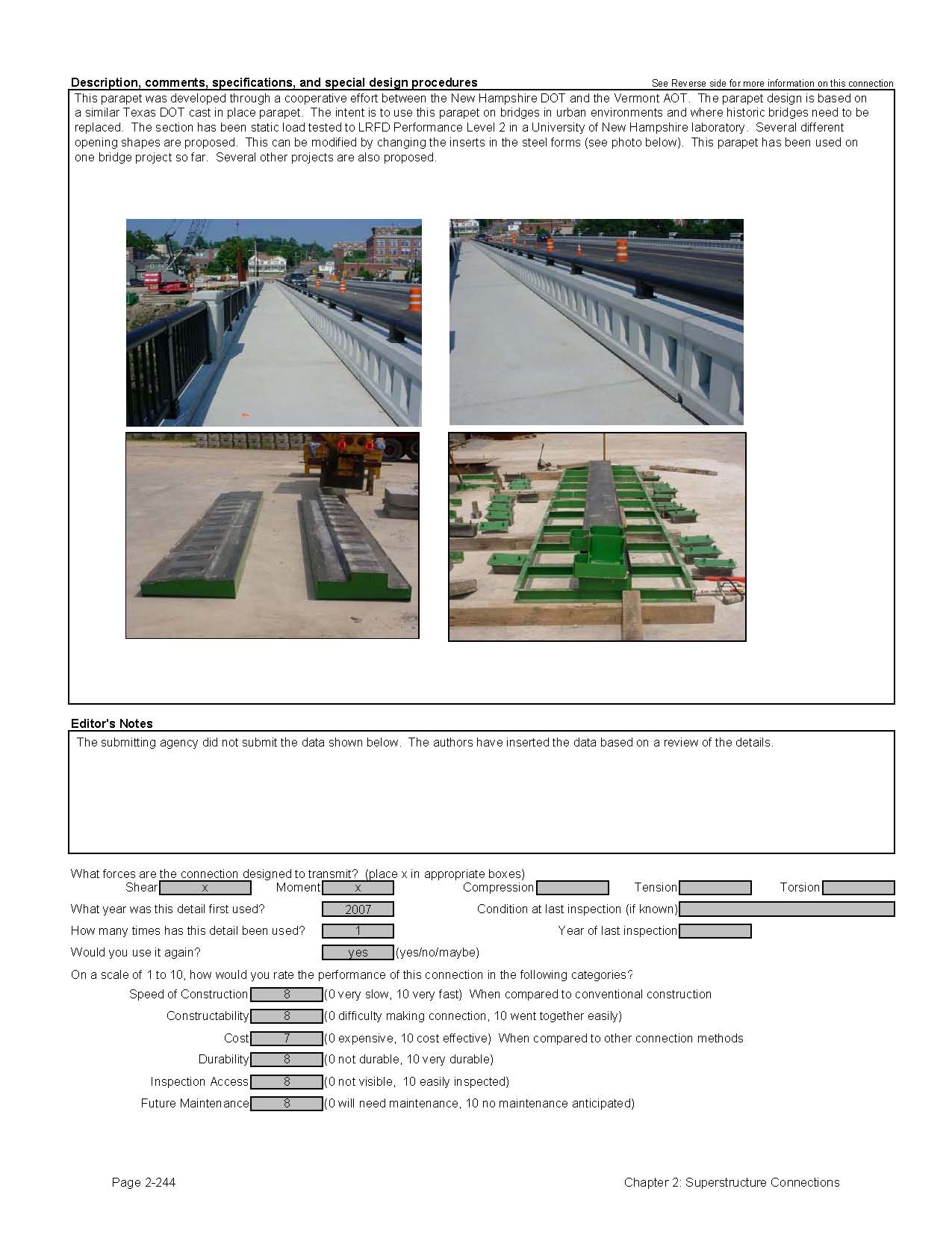
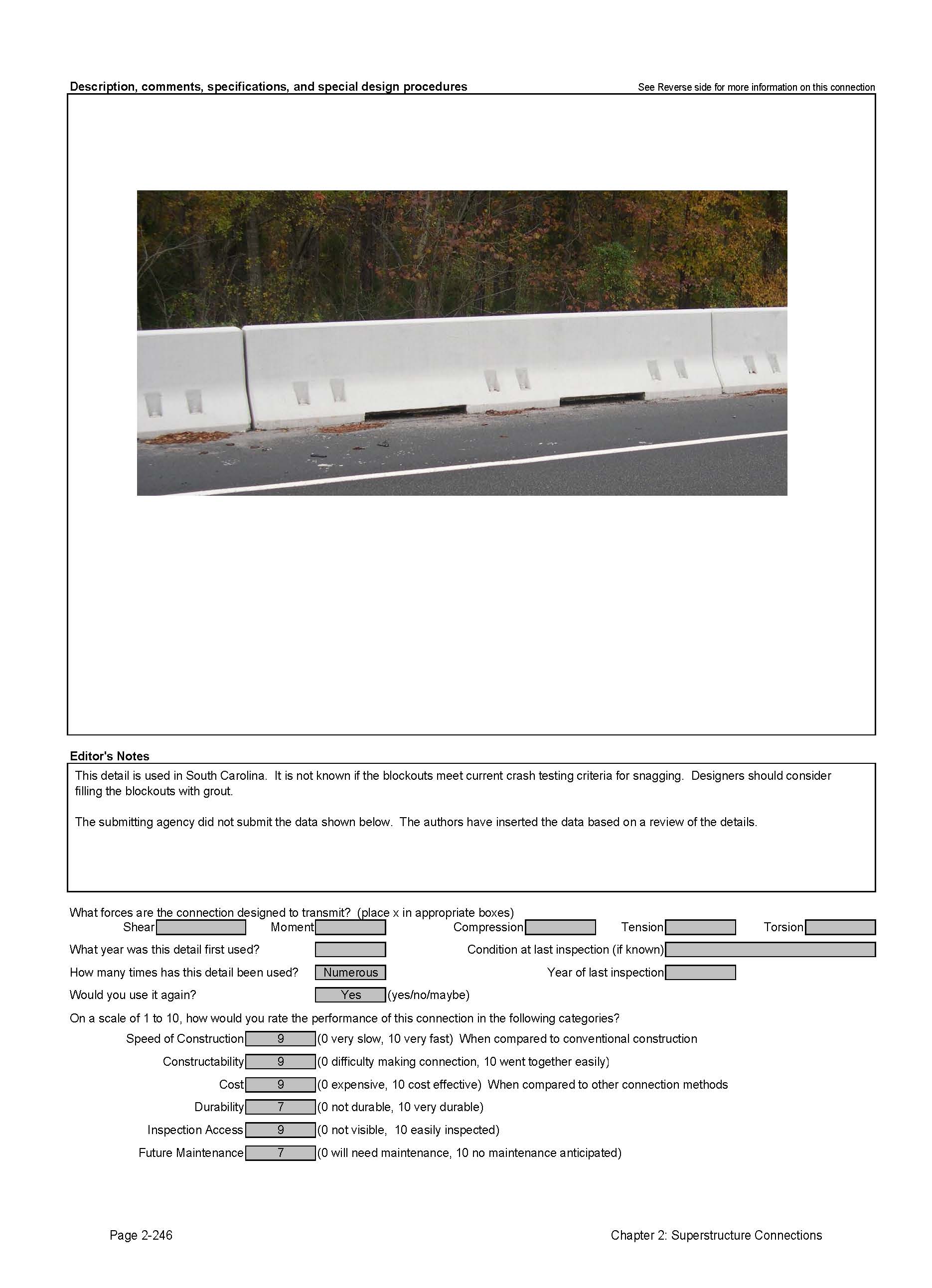
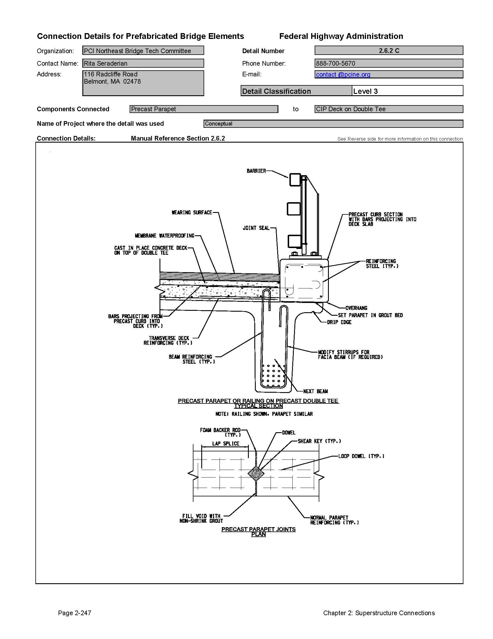
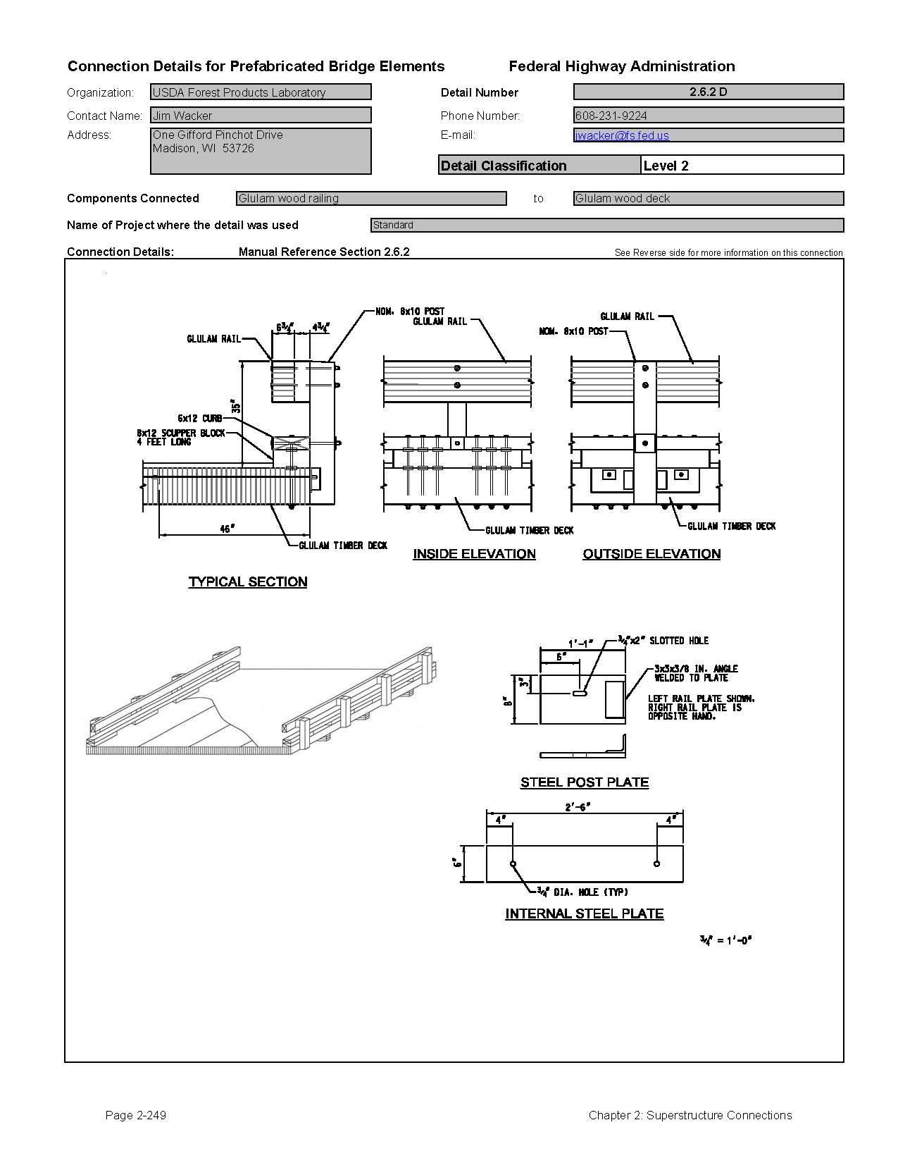
2.6.2 Barriers, Curbs and Railings
Section 2.1.1.4 covers connections of barriers and railing to full depth precast concrete deck panels. In some instances, prefabricated barriers and railings are attached to other elements such as cast-in-place concrete decks, and even timber decks. Refer to Section 2.1.1.4 for more information on barrier and railing connections.
The United States Department of Agriculture Forest Products Laboratory (USDA FPL) has developed standard details for timber barriers attached to timber bridges. This connection typically involves the used of bolts and split ring connectors. A split ring connector is a steel casting that is placed at the interface between two members loaded in shear. The connector greatly improves the resistance of the connection by spreading out the shear load to a larger area of wood. This essentially eliminates the crushing of wood against the side of the steel shear bolt. There is a significant amount of information on bridge railing connections at the USDA FPL website. Users of this Manual are encouraged to visit the Forest Products Laboratory website for more information on timber bridges (www.fpl.fs.fed.us).
2.6.3 Evaluation of Performance and Long Term Durability of Miscellaneous Superstructure Connections
The attachments of appurtenances, barriers and railings have different performance requirements. Attachments under bridge decks are not as exposed as barriers; however, these areas can be damp and subject to corrosion. Anchorages for appurtenances should be hot dip galvanized, according to ASTM A123 [48]. Designers may consider the use of stainless steel anchors for improved performance.
Barriers, curbs and railings experience some of the most severe exposure, especially in northern climates. Often the connection of a barrier to the deck is located at the gutter line. The joint between the barrier and the bridge deck should be protected from water infiltration. If this is not feasible, anchors used for the connection should be either hot dip galvanized according to ASTM A123 or made of stainless steel.
2.6.4 Estimated Construction Time for Connections
Exact timelines for construction are dependent on a number of factors including site access, traffic control, weather, crane locations and storage areas. It is possible to make reasonable estimates on construction time for the various systems discussed in this section.
Table 2.6.4-1 contains approximate installation times for the various systems included in this section:
| System | Minimum Installation Time | Comments |
|---|---|---|
| Miscellaneous appurtenances | 1 hour | Depending on the details, numerous connections can be made in one day |
| Steel Barriers | 1-2 Days | Time is for a typical single span bridge; larger bridges may take longer |
| Precast Concrete Barriers | 1-2 Days | This is for a typical single span bridge; larger bridges may take longer |
| Cast-in-place Concrete Barriers | 1-4 Days | The time of construction is a function of the number of pours required to complete the installation |
2.6.5 Recommendations for Improvements to Current Practices
The most important improvement to current practice is to cease the use of overhead epoxy adhesive anchoring systems. The 2006 collapse of the precast concrete roof panels in the Boston Central Artery Tunnel has indicated the inability of these anchors to support long-term tension loads.
2.6.6 Connection Detail Data Sheets for Miscellaneous Superstructure Connections
The following pages contain data sheets for the various miscellaneous superstructure connections. This information was primarily gathered from agencies that have developed and used the systems. Most data in the sheets were provided by the owner agency; the authors added text when an agency did not supply all requested information. The owner agencies also provide a comparative classification rating.
Each connection detail data sheet is presented in a two-page format. Users of this Manual can simply remove and copy a data sheet for use in developing a system for a particular project. These sheets are meant to give users a basic understanding of each connection that can be used during the type study phase of a project. The data sheets are not meant to be comprehensive, but do convey the component make-up of the detail, how it is meant to function, and provide some background on its field application. Users will need to investigate each connection further, consider site-specific conditions, and apply sound engineering judgment during design.
The key information provided for each connection is as follows:
- Name of the organization that supplied the detail
- Contact person at the organization
- Detail Classification Level
- Level 1
This is the highest classification level that is generally assigned to connections that have either been used on multiple projects or have become standard practice by at least one owner agency. It typically represents details that are practical to build and will perform adequately. - Level 2
This classification is for details that have been used only once and were found to be practical to build and have performed adequately. - Level 3
This classification is for details that are either experimental or conceptual. Details are included in this Manual that have been researched in laboratories, but to the knowledge of the authors, have not been put into practical use on a bridge. Also included in this classification are conceptual details that have not been studied in the laboratory, but are thought to be practical and useful.
- Level 1
- Components connected
- Name of project where the detail was used
- Manual Reference Section The section(s) of this Manual applicable to the particular detail shown.
- Connection Details
- Description, comments, specifications and special design procedures
- Forces that the connection is designed to transmit
- Information on the use of the connection (including inspection ratings)
- A performance evaluation of the connection rated by the submitting agency
Click images below to enlarge
Detail 2.6.2A

Detail 2.6.2B

Detail 2.6.2C
Detail 2.6.2D

| << Previous | Contents | Next >> |