Prefabricated Steel Bridge Systems: Final Report
4. New Concepts For Accelerated Bridge Construction
This chapter summarizes the evaluation process and the development steps for two new bridge concepts for accelerated steel bridge construction.
4.1 Evaluation of Existing Systems
In this section, all bridge systems presented in Chapter 2 are evaluated and assessed in light of the performance criteria presented in Chapter 3. The performance criteria discussed in Chapter 3 are grouped into four criteria. Each criterion consists of several categories with an assigned numerical rating. The total rating for each criterion is the summation of the numerical ratings for each category. The total score from all four criteria determines the ranking of the described systems. The four criteria with the associated sub-topics along with the numerical rating are presented below:
- Criteria I : Unit Configurations and Aesthetics (30%)
- Aesthetics (15%)
- Unit Configurations (15%)
- Unit configuration is judged by the cost (5%) and the ease of fabrication (10%).
- Criteria II : Construction and Erection (25%)
- Number of Joints (10%)
- Transverse (5%)
- Longitudinal (5%)
- Joint Details (5%)
- Ease of Erection (10%)
- Number of Joints (10%)
- Criteria III : Design Considerations (25%)
- Fatigue Resistance (10%)
- Joints Durability (5%)
- Span Length (10%)
- Criteria IV : Future Maintenance (20 %)
- Access and Inspection Efforts (10%)
- Protective Coatings (10%)
Tables 4.1 to 4.4 show the results of the evaluation for each stated criteria.
| Criteria I : Unit Configurations and Aesthetics | ||||
|---|---|---|---|---|
| Bridge Type | Aesthetics (15) |
Unit Configurations | Total Score (30) |
|
| Cost (5) |
Ease of Fabrication (10) |
|||
| Temporary and permanent truss systems | 7 | 4 | 10 | 21 |
| Railroad Flatcar | 12 | 4 | 8 | 24 |
| Composite Space Truss | 15 | 2 | 6 | 23 |
| Steel Girders and Concrete Deck | 12 | 5 | 9 | 26 |
| Under-Slung Truss | 7 | 3 | 7 | 17 |
| Cold-Formed Steel Plate Box | 13 | 3 | 7 | 23 |
| Criteria II : Construction and Erection | |||||
|---|---|---|---|---|---|
| Bridge Type | Number of Joints | Joint Details (5) |
Ease of Erection (10) |
Total Score (25) |
|
| Transverse (5) |
Longitudinal (5) |
||||
| Temporary and permanent truss systems | 3 | 3 | 3 | 9 | 18 |
| Railroad Flatcar | 5 | 5 | 5 | 9 | 24 |
| Composite Space Truss | 3 | 5 | 3 | 6 | 17 |
| Steel Girders and Concrete Deck | 5 | 5 | 4 | 9 | 23 |
| Under-Slung Truss | 5 | 5 | 4 | 7 | 21 |
| Cold-Formed Steel Plate Box | 5 | 5 | 4 | 8 | 22 |
| Criteria III : Design Flexibility and 75 Years Service Life | ||||
|---|---|---|---|---|
| Bridge Type | Fatigue Resistance (10) |
Joints Durability (5) |
Span Length (10) |
Total Score (25) |
| Temporary and permanent truss systems | 4 | 3 | 8 | 15 |
| Railroad Flatcar | 7 | 5 | 6 | 18 |
| Composite Space Truss | 7 | 5 | 9 | 21 |
| Steel Girders and Concrete Deck | 8 | 5 | 9 | 22 |
| Under-Slung Truss | 7 | 5 | 7 | 19 |
| Cold-Formed Steel Plate Box | 5 | 5 | 6 | 16 |
| Criteria IV : Future Maintenance | |||
|---|---|---|---|
| Bridge Type | Access and Inspection Efforts (10) |
Protective Coatings (10) |
Total Score (20) |
| Temporary and permanent truss systems | 4 | 4 | 8 |
| Railroad Flatcar | 7 | 7 | 14 |
| Composite Space Truss | 7 | 9 | 16 |
| Steel Girders and Concrete Deck | 8 | 8 | 16 |
| Under-Slung Truss | 6 | 7 | 13 |
| Cold-Formed Steel Plate Box | 3 | 8 | 11 |
Table 4.5 shows the overall numerical scoring of all bridge systems.
| Bridge Type | Unit Configurations and Aesthetics (30) |
Design Flexibility and 75 Years Service Life (25) |
Construction and Erection (25) |
Future Maintenance (20) |
Total Score (100) |
|---|---|---|---|---|---|
| Temporary and permanent truss systems | 21 | 15 | 18 | 8 | 62 |
| Railroad Flatcar | 24 | 18 | 24 | 14 | 80 |
| Composite Space Truss | 23 | 21 | 17 | 16 | 77 |
| Steel Girders and Concrete Deck | 26 | 22 | 23 | 16 | 87 |
| Under-Slung Truss | 17 | 19 | 21 | 13 | 70 |
| Cold-Formed Steel Plate Box | 23 | 16 | 22 | 11 | 72 |
It can be seen from the results that the top three bridge systems are the Steel Girders and Concrete Deck, Railroad Flatcar and Composite Space Truss in the order of ranking. In order to closely examine each of these systems it is important to study the advantages and disadvantages of each system. The results from this comparison will help in formulating the new bridge concepts. Following is an examination of these three systems:
The rating values shown in the tables are subjective and are based on the experience of the research team with consultation with consulting engineers, bridge fabricators, and contractors. While rating of the established criteria might slightly vary, the conclusions will remain the same.
Steel Girder / Precast Concrete Deck System
The steel girders with cast-in-place or precast decks are the most common elements in steel bridge construction.
Advantages:
- Improved efficiency with lighter steel beams (INVERSET brand system).
- Uses standard rolled shapes and welded plate girders.
- Economical / average construction costs.
- Can be fabricated with exact camber & skew to meet existing site requirements.
- Top of deck can be textured for riding surface.
- Easy & rapid erection & construction.
- Cast-in-place concrete not required at joints.
- Suitable for use as continuous spans.
- Durable since cast in controlled conditions.
Disadvantages:
- In the case of the INVERSET type system, units are cast in "Upside-Down" Position and must be turned over in manufacturing plant after casting.
- Weight limit for transportation may limit the use in long spans.
Railroad Flatcar System
As described earlier, the railroad flatcar system has been used in the construction of bridges on low-volume roads. The system relies on the availability of used and discarded railroad flatcars which limits the general use of this system. Therefore, this system is not promoted for widespread use; however, there are several aspects of the system, such as use of the flatcar as a stay-in-place form and details of the longitudinal joints, that can be implemented in a new general concept.
Advantages:
- Modular system.
- Easy and rapid erection & construction.
- Economical - about 2/3 cost of new bridge.
- Can be used on existing abutments & piers.
- Requires low maintenance if detailed properly.
- Effective, easily fabricated and constructed y longitudinal joints.
Disadvantages:
- Unknown fatigue resistance.
- Use only allowed on low-volume roads.
- Limited availability of usable flatcars.
- Supports must be at flatcar axle locations.
- Limited span lengths.
- Not suited for use as continuous spans.
Composite Space Truss System:
The composite space truss system scored the highest in aesthetics when compared to all other systems.
Advantages:
- High stiffness / weight ratio.
- Alternate / redundant load paths.
- Aesthetically pleasing appearance.
- Durable precast concrete deck slabs.
- Has great potential for modular design.
- Has potential for greater span lengths.
- Cast-in-place concrete not required at joints.
- Possible low maintenance if detailed properly.
- Suited for use as continuous spans.
Disadvantages:
- Current high cost due to complex fabrication.
- Complex welded "K & Y" joint fabrication.
- Large surface areas of steel tubing exposed.
- Requires lateral & vertical diaphragms at supports.
- Large number of transverse joints between panels.
- Possible need for riding surface preparation.
- Erection more difficult than other systems.
- Critical longitudinal connectivity of modules.
This system was closely examined by the research team due to its aesthetically pleasing appearance. The system could be modified as shown in Figure 4.1 to expand its potential. Figure 4.1 shows a bridge concept consisting of several modular units tied together to form a bridge. Each modular unit consists of a fully prefabricated concrete deck supported by a space truss. The concrete deck can be prefabricated at the factory and transported to the bridge site or prefabricated close to the bridge and lifted into place.
Figure 4.1 Modified Composite Space Truss System

The research team contacted several steel bridge manufacturers inquiring whether the tubular truss system can be easily manufactured with their existing equipments and fabrication techniques. All contacted fabricators voiced reservation on the practicality of this system and on their willingness to move into this type of fabrication. This fact alone will hinder the acceptance and widespread use of such system in the United States. Therefore, while at first glance this system offered the best option, the research team believes that it does not meet the objectives of the project.
4.2 New Systems Development
The above systems evaluation indicates that a new system that combines the advantages of the steel girders with concrete decks and the railroad flatcar systems while minimizing or eliminating their disadvantages could offer the best options. The following criteria are used in establishing minimum performance limits for the new systems:
- Improved efficiency with lighter steel beams.
- Uses standard rolled shapes and welded plate girders.
- Economical / average construction costs.
- Can be fabricated with exact camber & skew to meet existing site requirements.
- Easy & rapid erection & construction.
- Minimize number of joints.
- Suitable for use as continuous spans.
- Durability (Sufficient fatigue resistance to meet 75 years design life.)
- Extending maximum span lengths.
- Modular system.
- Can be used on new or existing abutments & piers.
- Requires low maintenance.
- High stiffness / weight ratio.
- Alternate / redundant load paths.
- Aesthetically pleasing appearance.
- Designed for HL-93 loading.
4.2.1 Modular Cast-in-Place System
Early in the development stage it was recognized that transportation limitation will play an important role in determining the modular unit configuration and the maximum span length. Also, the number and details of the transverse and longitudinal joints would have a marked effect on the durability of the new systems. These limitations played an important part in the choice of the new concept. In addition to achieving the goal of accelerated construction, it is important to limit or eliminate any type of forming and shoring; in other words, all construction work needs to be performed "from the top".
The research team studied several concepts before arriving at the concept presented in Figures 4.2 to 4.5. The new concept combines the traditional steel girders and deck system with some features of the railroad flat car system. Figure 4.2 shows the basic components of the proposed system. The new system relies on a wide interior unit with depth varying between 9 and 12 ft and a variable width exterior unit. These units are fabricated to create a self contained stay-in-place steel pan form. A cold formed steel plate or corrugated metal form are welded to the top of the steel girders under factory controlled conditions followed by welding a welded wire mesh to the plate as shown in Figures 4.2(b). As seen in Figure 4.2(a) the steel pan depth is only 4 inches, the welded steel mesh is welded to the top of the steel pan. The depth of cast-in-place concrete deck will vary between 6 to 8 inches and will provide sufficient concrete cover to the steel mesh.
The welded wire mesh is designed to provide the necessary deck reinforcement. The stay-in-place steel pan form eliminates the need for forming or shoring and allows all construction work to be performed "from the top".
Figure 4.2(a) Exterior and Interior Units Details
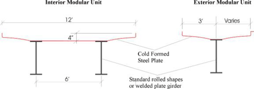
Figure 4.2(b) Adding Deck Reinforcement

The units are transported using traditional methods of transportation to the construction site and erected in place to form the bridge system as illustrated in Figure 4.3. Each unit is tied to adjacent units using steel bolts spaced at predetermined distances. Once the units are assembled and tied together, sections of steel mesh for lap-splicing are placed on top of the longitudinal joints and tied to the welded steel mesh as shown in Figure 4.4. As stated earlier, the steel pan depth is only 4" and the wire mesh sections are welded at the manufacturer.
It should be pointed out that while Figure 4.2 shows a unit width of 12 feet which is later used in the optimization work presented in Chapter 6, it is anticipated that the practical width limit will be between 9 to 10 feet to facilitate transportation of the units without requiring special permits.
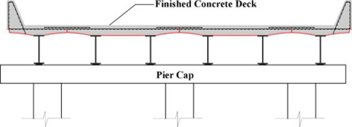
The concrete is then placed in the stay-in-place steel pan forms to form the bridge deck, as shown in Figure 4.5. The use of fast setting concrete will allow traffic on the bridge within three days. The welded wire fabric placed on top of the joints are tied to the existing steel mesh using common wire ties. The cast-in-place concrete depth is 8" deep which places the welded wire fabric approximately at mid depth of the slab.
Figure 4.3 Erection and Assembly
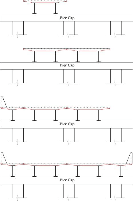
Figure 4.4 Installation of Steel Mesh Over Transverse Joints
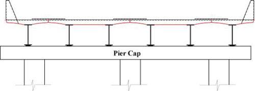
Figure 4.5 Placement of Concrete Deck
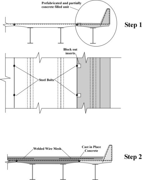
To facilitate construction and simplify the field work for forming and casting the exterior unit the exterior unit can be prefabricated and partially filled with concrete as shown in Figure 4.6. Block outs are fabricated during the construction of the unit to facilitate connecting and bolting the unit to adjacent interior units. The exterior unit is placed and tied to the interior unit as shown in step 1 of Figure 4.6. The welded wire fabric sections are then placed over the joints as earlier described. The cast in place concrete is then placed to form the deck as shown in Figure 4.6 (step 2).
If desired, continuity for live loads could be easily achieved by providing negative moment reinforcement over the support area prior to casting the deck concrete.
Figure 4.6 Exterior Unit Details
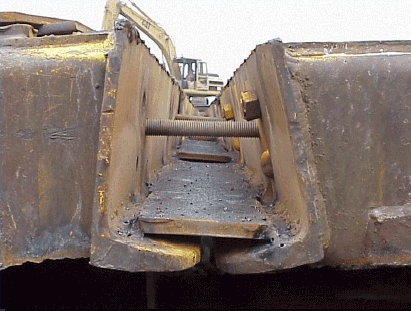
It is envisioned that a simple joint detail as shown in Figure 4.7 will provide the necessary durability and performance of the proposed system. Joint details and the optimum number of bolts required to develop monolithic behavior will be established through research and testing of the proposed modular bridge system.
Figure 4.7 Transverse Joint Details
The method described above will allow accelerated bridge construction, while eliminating all the construction joints, typical in modular bridge systems. Long term durability could be achieved through applying durable coatings to the interior and exterior of the modular units at the factory or through using high performance steel.
The proposed concept solves many of the problems associated with transverse and longitudinal joints. Though a very significant amount of concrete must still be poured to construct the bridge deck, the work can be performed without much intrusion to whatever is going on below the bridge. Once the units are up, the deck form plates provide a safe work platform while also adding some stability (note that these plate should probably be corrugated to ensure their own stability). The system achieves all minimum performance levels established during the conceptual development phase as will be seen from the optimization process presented in Chapters 5 and 6.
4.2.2 Modular Precast System
Similar to the previously discussed system a modular precast system is proposed. The system consists of two steel girders spaced at 6 feet apart supporting a precast concrete deck. The total width of the modular precast unit is 12 feet as shown in Figure 4.8. The width of the exterior unit is variable to allow simple customization of the system. The concrete parapet is cast monolithically with the deck as shown in Figure 4.8.
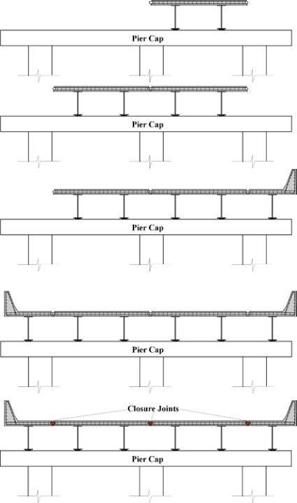
The modular units are transported to the job site using conventional transportation methods and erected in place to form the bridge structure, as illustrated in Figure 4.9. Once the units are assembled, locking bars are inserted into the longitudinal joints followed by casting the joint material. Durability of the joint could be achieved through proper detailing as well as the use of polymer concrete or epoxy as the joint material.
Figure 4.8 Precast Modular Bridge System
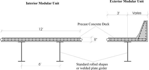
Figure 4.9 Assembly of Precast Modular Bridge System
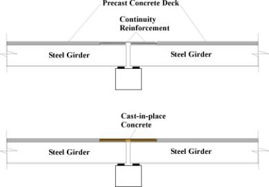
Continuity for live loads could be achieved by extending the deck reinforcement at either side of the modular unit as shown in Figure 4.10. Additional reinforcement is added and tied to the extend reinforcement followed by placement of cast-in-place concrete over the support as shown in Figure 4.11.
Figure 4.10 Continuity Details

Figure 4.11 Precast Modular Bridge System Made Continuous
Transportation limitation will limit the maximum span lengths that could be achieved with this system. These limits are established in the optimization analysis presented in Chapter 6. It should be pointed out that up-side-down casting techniques or prestressing the steel are variations that could result in beneficial effects and should be considered in future research.

