*STARNET
System Verification Plan
Version 1.0
Prepared for the Sacramento Area Council of Governments
and associated agencies in the Sacramento region
by Siemens ITS

![]()
*STARNET
System Verification Plan
Version 1.0
Prepared for the Sacramento Area Council of Governments
and associated agencies in the Sacramento region
by Siemens ITS
![]()
|
Document Description |
Date |
Version Number |
|
First draft for review |
October 11, 2006 |
0.1 |
|
Second draft for review |
October 25, 2006 |
0.2 |
|
Incorporate comments and make consistent with updated concept of operations and requirements |
October 29, 2007 |
1.0 |
|
|
|
|
1.2 Purpose of Verification Plan
Appendix A – Test Case Trace Matrix
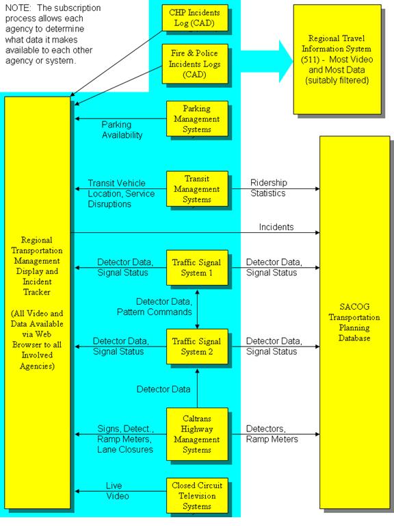
Figure 1 - Major Data Flows in STARNET
The Sacramento Transportation Area Network, or STARNET, is an information exchange network that will be used by the operators of transportation facilities and emergency responders in the Sacramento region of California. STARNET will enable the real-time sharing of data and live video, and refinement of joint procedures pertaining to the operation of roadways, public transit, and public safety activities. It will thereby assist operations personnel in the coordination of their activities and in providing the public with comprehensive information about current travel conditions and options.
This Verification Plan presents the test methods that will be used to demonstrate that the completed and deployed system is compliant with the system requirements. This version of the Verification Plan describes the test methods for the system requirements as documented in version 0.1 of STARNET System Requirements. The System Requirements will be modified several times during the development of the system. The requirements will be modified to incorporate agency comments during project planning, and then modified during the procurement process, and again during system development. The Verification Plan should be reviewed after any modifications to the system requirements to determine if it also requires modification. System requirements were derived from User Needs described in the document titled STARNET Concept of Operations. The reader is advised to review the operation scenarios to gain an understanding of the goals and context of STARNET.
The concept of operations is fully described in the STARNET Concept of Operations. The description here provides only a brief overview.
Public agencies in the Sacramento urban area will exchange real-time information among themselves to facilitate improved coordination, and therefore effectiveness, of their transportation and emergency response activities. These agencies will also provide relevant real-time information to travelers via the region’s 511 travel information distribution system.
As illustrated in Figure 1, real-time information will be extracted from the various computer systems operated by the involved agencies and appropriate portions thereof will be sent to a Regional Transportation Management Display system, the 511 travel information system, and the SACOG Transportation Planning Database. Some information will also be sent to peer systems operated by other agencies. The information transmitted will include data and streaming live video.
The following are the categories of different users or consumers of the transmitted information. A STARNET organization is one that directly provides or consumes exchanged information. Non-STARNET organizations may obtain a one-way feed of selected information from the 511 travel information system.
· Operators in STARNET organizations
· Computers operated by STARNET organizations
· Computers operated by non-STARNET organizations
· Planners at SACOG
· The public
Operators in STARNET organizations will use the Regional Transportation Management Display to view data and video describing current conditions, and to enter information about current incidents and planned events. Computers operated by STARNET organizations will use real-time information to make decisions, alert operators, and take automatic actions in support of more efficient transportation system operation and emergency response. Computers operated by non-STARNET organizations may use real-time data for various purposes such as enhanced travel information distribution services, transportation research, and transportation system performance monitoring. Planners at SACOG (the Sacramento Area Council of Governments) will use historical data gathered in the Transportation Planning Database to measure the transportation system’s past performance and to predict its future performance. The public will use real-time travel information (data and video) to gain knowledge of current travel conditions, to make decisions about the time, mode, and route of travel, and to estimate and inform others of their likely time of arrival.
Figure 1 - Major Data Flows in STARNET
A verification plan is a document that describes the objectives, scope, approach, and focus of a system’s acceptance testing effort. The verification plan describes the efforts needed to determine the acceptability of the developed system.
The Verification Plan states what the items to be tested are, how the item will be tested, and describes the test environment.
The objective of this verification plan is to provide a plan to verify the system produced meets each requirement as listed in the System Requirements Table. The system’s compliance to the requirements will be verified by: testing the software, analysis, or other means It is expected that the System Requirements will evolve as an implementation firm is selected, and through the course of design and implementation. The Verification Plan should be modified to capture the changing requirements.
This verification plan will describe the following requirements for STARNET system acceptance testing during initial deployment:
· Software and Hardware items to be tested (general description);
· Features to be tested;
· Testing tasks to be performed.
High-level summary test cases are provided with the draft version of this plan. The test cases are later refined and step-by-step procedures are developed. The step-by-step procedures will be used to execute the test. The detailed test procedures are to be written by the system integrator (Integrator).
The following documents were used as sources of information for the verification plan:
STARNET Concept of Operations version 2.0
STARNET System Requirements version 1.0
The System Requirements assume that the computer systems involved in STARNET are interconnected in a logical many-to-many network. Any computer system (STARNET node) can obtain data directly from any other computer system (STARNET node). There is no hierarchy or centralization. However, not all STARNET nodes have the same data available nor the same use for data from other nodes. Therefore, at least initially, data will not flow between all nodes.
The System Requirements assume that a computer system can establish a persistent request (subscription) with any other node to have real-time data automatically sent (published) either periodically or upon change. Hence data can flow continuously and without human involvement, other than configuration of subscriptions. A node may choose to reject a subscription so that agencies maintain control of what data are allowed to flow to what other nodes.
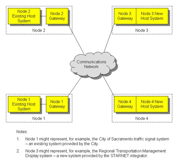
Each STARNET node is logically comprised of a “host system” and a “gateway”. The gateway provides STARNET interface functionality, including management of subscriptions and publications, and translation between STARNET and host system data formats and communication protocols. The host system provides the remainder of the functionality of that node. For existing host systems, the gateway will be provided by the STARNET system integrator and will likely function on a new computer separate from any computer used by the existing host system. For new host systems being provided by the STARNET integrator (e.g., Regional Transportation Management Display system, and 511 system), the gateway may be integral with the host system. Figure 2 illustrates this architectural concept, of all nodes having at least a logical gateway. The gateways communicate with each other using a single standard protocol and message set. On the other hand, each node may use a different protocol and message set for “internal” communications between its gateway and its host system.
Figure 2 - STARNET Gateways
The term “object” is used to refer to any entity for which data are exchanged via STARNET. Examples of objects include traffic signals, vehicle detector stations, light rail vehicles, incidents, nodes, etc. Among other things, all objects have a location (e.g., latitude and longitude), and an owner. The owner of an incident is the name of the agency of the operator that created the incident record in the Regional Transportation Management Display system (if created manually) or the name of the source node, in the case of incident records created automatically by the Regional Transportation Management Display system.
A “message” in the context of data communications, is a predefined, structured set of data passed between computer systems. The intent is for node-to-node communications to use standard messages, such as those defined by the Traffic Management Data Dictionary (TMDD) and IEEE Standard for Common Incident Management Message Sets for Use by Emergency Management Centers (IEEE 1512), where feasible. The data actually included within a particular transmittal may be a subset of the data allowed for in the standard structure for a particular message type, as many fields are optional. Due to dependence on legacy interfaces, communications between a host system and its STARNET gateway will likely have to use different messages, or other data transfer techniques, than those used between nodes. The gateway will translate.
The STARNET components to be tested are referred to as the Unit Under Test. The Unit Under Test consists of software components developed by the system integrator (Integrator) as well as hardware and commercial off-the-shelf (COTS) items provided and integrated by the Integrator.
Existing host systems that are integrated, but not modified, as part of the STARNET Project are used to facilitate the test, but are not part of the Unit Under Test. The ability of the Gateway to successfully integrate with the existing host system is tested, as well as the communications between Gateways. Existing host systems that are modified as part of the STARNET implementation are part of the Unit Under Test, though only those functions altered or added by the STARNET project are tested. Modifications to existing host traffic signal systems may be necessary in order for them to receive and use detector data from another node, and to receive pattern request commends from another node and to act upon these requests. In addition, the SACOG Regional Transportation Planning database may need modifications in order to accommodate the storing of STARNET data. The Integrator will determine the extent that these existing host systems need to be modified and will make the necessary changes to the Verification Plan.
This section outlines the test cases that will be used to verify compliance with the STARNET System Requirements. The requirements verified by each test case are provided in Appendix A with the associated test cases identified in the right hand column. The test scenarios for each test case are provided in Appendix B. The test procedures for each test case will be developed by the System Integrator as they are heavily dependant on the specifics of the implementation. The System Integrator will also expand the test cases, as necessary, to demonstrate that every aspect of each requirement is implemented.
Regional Display Administration Test Case (Reg. Displ. Admin.)
This test case will set the system settable parameters and establish operators. The configuration set in this test case will be used to demonstrate the functionality in the remaining test cases.
Video Distribution Administration Test Case (Video Dist. Admin.)
This test case verifies that an administrator can add and delete cameras, configure video feeds (such as frame rate, quality levels, image size and bandwidth), and assign different privileges to users and user groups.
Node Administration Test Case (Node Admin.)
This test case verifies that STARNET subscriptions of various types can be established and maintained.
Regional Display Test Case (Reg. Displ.)
The Regional Display test case verifies those requirements that are associated with an operator launching the Regional Display, viewing data, and navigating the map. All nodes publishing data to the Regional Display will be involved in this Test Case.
Video and Camera Control Test Case (Vid. Cam. Con.)
The Video and Camera Control test case verifies that an operator can select cameras and control them using the Regional Display.
Incident Tracker Test Case (Incid. Track.)
The Incident Tracker test case verifies those requirements associated with creating, modifying and deleting incidents. Also verified will be system paging in response to incident triggers.
511 Web Page Dynamic Elements Test Case (511 Web Page)
This test case is very similar to the Regional Display Test Case. The focus of this test case is to verify that data to be excluded for the 511 Web Page dynamic elements are not available. This test case will also include viewing video via the 511 Web Page.
Node Status Monitoring Test Case (Node Stat. Mon.)
The Node Status Monitoring test case verifies those requirements that are associated with node-to-node communication health, including verifying that nodes are operational and notifying the appropriate person in the event of a loss of communications.
Traffic Signal System Test Case (Traff. Signal.)
This test case verifies that relevant Traffic Signal host systems can receive and act upon vehicle detector data and pattern command requests from other nodes.
The primary objective of the formal acceptance testing of STARNET is to exercise the system under test to demonstrate full compliance with the system requirements as found in STARNET System Requirements version 0.1 and subsequent modifications. The System Integrator will use the final system requirements, final system design, and the final Verification Plan to develop detailed, step-by-step acceptance testing procedures for each system deliverable.
Each requirement in the STARNET System Requirements is reviewed and a method of verification of that requirement is assigned. The verification method will be one of the following two methods:
Analysis: Analysis is a means of verifying a requirement through reasoning. Analytical methods can include looking at the code, output files, or through mathematical computations. In some cases, a requirement can be verified by looking at the name on the device and see that it is the brand specified.
Test: Test is comparison between an actual system output when a test case is performed and an expected result.
For each requirement assigned the “test” method, the requirement will be demonstrated by the execution of one or more test cases. Test cases are scenarios that allow logically related requirements to be verified together. The STARNET System Requirements, modified to include the assignment of test methodology and test case(s) to each system requirement, are provided in Appendix A.
Using the Test Cases and the Test Procedures, the system integrator will define in detail the test environment needed for each test case. The test environment provides the hardware, software, and facilities needed to support the proper execution of the test.
System problems, errors, failures, or malfunctions that are not in compliance with the contract requirements are to be assigned to severity categories such as the following:
· Severity 1 – A hardware or software problem that results in the permanent absence of one or more required features of the system.
· Severity 2 – A hardware or software problem that causes occasional failure of, or disruption of access to, one or more required features of the system.
· Severity 3 – A hardware or software problem that otherwise causes a required feature of the system to be incomplete, out of tolerance, or incorrect, or otherwise fails to fulfill a requirement.
Each deliverable subject to acceptance testing will first be subjected to demonstration tests that involve one-time exercise and demonstration of functionality by the system integrator, witnessed by a SACOG representative. Each deliverable will also be subjected to a 30-day burn-in test. The 30-day test will consist of 30 consecutive days (including weekends and holidays) of use and exercising of the system by the agencies, and by the public when feasible.
Problems of severity 1 or 2 found during demonstration testing must be corrected before the 30-day burn-in test can commence. Severity 3 problems found during demonstration testing need not delay commencement of the 30-day burn-in test, and the 30-day test can be paused by the system integrator in order to install system upgrades aimed at correcting severity 3 problems. However, at least 15 consecutive uninterrupted test days must follow each such system change. Also, all demonstration tests for that deliverable must be repeated after each such system upgrade.
Since the system will be delivered in multiple stages, work performed as part of a particular deliverable may “break” functionality provided in a previous deliverable. Although demonstration testing of former deliverables will not be required during each subsequent deliverable, any problems found in previously delivered and accepted components during the 30-day burn-in test for a subsequent deliverable, will be treated as a failure of the previous deliverable. Such failures will be treated as if the former deliverable were part of the current deliverable. Therefore, acceptance of each deliverable is preliminary only, until the last deliverable is accepted.
This Verification Plan addresses all requirements included in the System Requirements version 0.1. Those initial STARNET System Requirements will be used in the Request for Proposals for integration services for the initial STARNET deployment. As such, they represent desired functionality that may not be fully achievable within the constraint of funding available for the initial deployment. In conjunction with the STARNET stakeholders, during contract negotiations or later, the System Integrator will develop a final list of requirements that can be implemented within the project constraints.
The System Integrator will then modify the test cases in this Verification Plan accordingly, and develop the detailed Acceptance Test Procedures. After completion of each test, the System Integrator will develop the Acceptance Test Report that will document the results of the test, any anomalies, and their resolution.
Before the execution of the STARNET acceptance test, it is necessary to have the proper support hardware and software setup to facilitate testing. This setup varies from test case to test case and will be identified in detail by the System Integrator. It is expected that the Test Environment will consist of the existing host systems and the new host systems, gateways, communications devices, hardware, and off the shelf software developed and/or integrated by the System Integrator.
It is envisioned that simulators will be unnecessary, but the System Integrator will make the final determination. Simulators are typically used to provide the stimulus to the system so that functions can be tested. Simulators are not part of the operational system and are used only to facilitate testing. The operational system in various configurations is proposed to be used to conduct the test.
The following table defines acronyms and uncommon terms used in this document and in the companion STARNET System Requirements Spreadsheet, which contains details of each system requirement.
Table 1 Terminology
|
Term |
Meaning |
|
511 |
The national travel information telephone number, also used as an adjective for related items, as in “the 511 web site”. |
|
Active Incident |
An incident with an actual Start Time in the past and an End Time that is in the future or estimated. |
|
ATMS |
Advanced Traffic (or Transportation) Management System |
|
Caltrans |
California Department of Transportation |
|
CAD |
Computer Aided Dispatch system that records incident information |
|
CCTV |
Closed Circuit Television |
|
CHP |
California Highway Patrol |
|
Far Future Incident |
An incident with a future Start Time that is not within the configurable Near Future Incident time limit. Also, an incident with an estimated past Start Time that is not within the configurable Impending Future Incident time limit. |
|
FHWA |
Federal Highway Administration |
|
FTP |
File Transfer Protocol |
|
Gateway |
That portion of a STARNET node (computer system) that provides the STARNET interface (see also Host System, Node) |
|
Host System |
That portion of a STARNET node (computer system) that excludes the STARNET interface (also see Gateway, Node) |
|
IEEE |
Institute of Electrical and Electronics Engineers |
|
Impending Future Incident |
An incident with a future or past Start Time that is within the configurable Impending Future Incident time limit. |
|
Incident |
An event of interest to operators (see below) or the traveling public. E.g., an accident on a roadway, a planned lane closure, a building fire, a truck height or weight restriction, a transit service disruption, an air show, etc. Also see Far Future Incident, Near Future Incident, Impending Future Incident, Active Incident, and Past Incident. |
|
Incident Start Time |
The date and time at which an incident started – can be estimated or actual. |
|
Incident End Time |
The date and time at which an incident ended – can be estimated or actual. |
|
ITS |
Intelligent Transportation Systems |
|
Jitter |
Variation in the travel time of data packets on a network due to changes in conditions such as the available bandwidth, congestion at network switches, or routing of packets. |
|
Message |
Structured set of data transmitted between computer systems. OR The text displayed on a changeable message sign. |
|
Near Future Incident |
An incident with a future Start Time that is within the configurable Near Future Incident time limit but not within the Impending Future Incident time limit. |
|
Node |
A computer system connected to the STARNET network (see also Host System, Gateway) |
|
NTCIP |
National Transportation Communications for ITS Protocol |
|
Object |
A logical entity for which associated data are sent over the STARNET network (e.g., traffic signal, light rail vehicle, incident, node, etc.) |
|
Operator |
An agency employee or contractor configuring or using a STARNET node for transportation or emergency management (also see Traveler). |
|
Past Incident |
An incident with an actual End Time in the past. |
|
Regional Transportation Management Display |
A STARNET node to be provided by the STARNET integrator that will, among other things, automatically create incident records based on incident data from other nodes, allow operators to create and edit incident records, and display current data and live video. Also referred to as Regional Display. |
|
RT |
Sacramento Regional Transit District – largest transit operator in the Sacramento region. |
|
SACOG |
Sacramento Area Council of Governments |
|
SOAP |
Simple Object Access Protocol |
|
STARNET |
Sacramento Transportation Area Network |
|
Start Time |
The start time of an incident (can be either estimated or actual). |
|
Traveler |
A person interested in information about current travel conditions in the Sacramento region. |
|
XML-Direct |
A simple XML document retrieval standard defined in NTCIP 2306 |
|
XML-SOAP |
A web services based XML data transfer standard defined in NTCIP 2306 |
Table 2 System Requirements has the following columns:
· Grouping – A heading indicating the type of requirements in a group.
· Requirement Number – A unique number assigned to each requirement and preceded by the letters SR – for example, SR-123.
· Requirement Text – A formal and concise description of the requirement.
· Priority – The implementation priority assigned to each requirement (High, Medium, and Low).
· Test Method – This field indicates whether it is expected that the requirement’s functionality will be verified using analysis or test methods. If the requirement is verified using testing methods, the abbreviations of the test case or cases are listed.
The requirement number provides a unique identifier which serves as a shorthand means of referring to a particular requirement.
The requirement priority reflects the importance of this requirement to the stakeholders. Lower priority implies that the stakeholders put less value on the requirement and are more amenable to the requirement not being met or only partially met.
The requirements listed in Table 2 are consistent with System Requirements v1.0.
Table 2 System Requirements
|
Grouping |
No. |
Requirement |
Priority |
Test Method |
|
DEFINITIONS |
SR-1 |
In addition to object-specific definitions in other requirements, objects of all types, data available from the source node shall include the following universal data: object type, identifier, owner (agency), location (lat/long), location description (including direction where relevant), and date/time of last update; except that light rail vehicles and buses shall not have a location description. |
High |
Reg. Displ., 511 Web Page |
|
|
SR-2 |
When timestamps are unavailable from the host system, the gateway nearest the source system shall provide the timestamp. |
High |
Reg. Displ. |
|
|
SR-3 |
Objects types shall include: incidents, vehicle detectors stations, traffic signals, CCTV cameras, changeable message signs, ramp meters, parking garages, light rail vehicles, buses and STARNET nodes. |
High |
Reg. Displ. |
|
Vehicle Detector Data Definition |
SR-4 |
Vehicle detector data shall include count (by class), average occupancy, average speed, detector health (e.g., OK, suspect, soft failed, hard failed, disabled, and no response), and the time period for which the data applies, as available from the host system. |
High |
Reg. Displ., 511 Web Page |
|
SR-5 |
Vehicle detector data shall be available per detector per lane and per station, as available from the host system. A station is defined as an aggregation of available data from all lanes in a particular direction at a particular location. |
High |
Reg. Displ., 511 Web Page |
|
|
Slowdown Data Definition |
SR-6 |
Slowdown data shall include the route, beginning and ending (if more than one station is involved) extents, the average speed across the stations, and the time of last update. The components of universal data are not applicable to Slowdown data. |
High |
511 Phone Sys |
|
Traffic Signal Data Definition |
SR-7 |
Traffic signal data shall include operating mode, basic timing parameters, and pattern commands, as available from the host system. |
High |
Reg. Displ. |
|
|
SR-8 |
Traffic signal operating modes shall include the following: off-line, flash due to failure, police manual control, police flash, programmed flash, preempt, priority, standby, free, and coordinated. |
High |
Reg. Displ. |
|
|
SR-9 |
Traffic signal current basic timing parameters shall include the following: plan or pattern number, cycle length if coordinated, offset if coordinated, and phase sequence if coordinated. |
High |
Reg. Displ. |
|
|
SR-10 |
Traffic signal pattern commands shall consist of a request to implement a certain pattern at selected signals at another traffic signal node. |
High |
Reg. Displ. |
|
SR-11 |
Ramp meter data shall include ramp meter status and metering rate, as available from the host system. |
Medium |
Reg. Displ., 511 Web Page |
|
|
|
SR-12 |
Ramp meter states shall include the following: out of service, in service but not currently metering, and currently metering; as available from the host system. |
Medium |
Reg. Displ., 511 Web Page |
|
CMS Data Definition |
SR-13 |
Changeable message sign data shall include sign status and message content, as available from the host system. |
High |
Reg. Displ., 511 Web Page |
|
|
SR-14 |
Sign states shall include out of service, in-service but blank, displaying a routine message (e.g., travel time or Buckle Up), and displaying a non-routine (e.g., incident) message; as available from the host system. |
High |
Reg. Displ., 511 Web Page |
|
Incident Data Definition |
SR-15 |
Incident data shall include: incident type, incident description, impact (none, low, moderate, high, highest), incident record creation data/time, route, direction, area, start date/time (and whether estimated or actual), end date/time (and whether estimated or actual), 511 phone message, 511 phone announce time, whiteboard entries, and creator's name, as available from the host system. For an incident, the object location (lat/long) determines the location of the icon on the map. |
High |
Reg. Displ., 511 Web Page |
|
|
SR-16 |
Incident types shall include the following: roadway incident, transit incident, disaster, planned event, planned road changes, truck restriction, operations and test. |
High |
Reg. Displ., 511 Web Page |
|
Ridership Statistics |
SR-17 |
Ridership Statistics data shall include: unlinked passenger trips, passenger miles and average trip length as available from the host system. |
|
Node Admin. |
|
Parking Garage Data Definition |
SR-18 |
Parking garage data shall include the percentage filled and the number of spaces available, hours of operation, currently open/closed, as available from the host system. |
High |
Reg. Displ., 511 Web Page |
|
Light Rail Vehicle Data Definition |
SR-19 |
Light rail vehicle data shall include the route, line, destination, number of cars in the train, in service indicator, passenger counts, and speed, as available from the host system. |
High |
Reg. Displ., 511 Web Page |
|
Bus Vehicle Data Definition |
SR-20 |
Bus vehicle data shall include the route, destination, in service indicator, passenger counts, and speed, as available from the host system. |
High |
Reg. Displ. |
|
Camera Data |
SR-21 |
Camera data shall include: whether the camera is available for viewing, cut from public feed, the control status, ID of the current (most recent) operator and two previous most recent operators within the last “x” number of seconds, where “x” is a system configurable parameter. |
High |
Reg. Displ, 511 Web Page |
|
|
SR-22 |
The control states shall consist of: no control, out of service, no permission, in use, locked-override available, and locked. |
High |
Vid. Cam. Con. |
|
|
SR-23 |
A camera shall be considered "in use" if a camera control request has been sent to the camera in the last "y" seconds, where as "y" is a system configurable parameter. |
High |
Vid. Cam. Con., Vid. Sys. Admin. |
|
|
SR-24 |
Video feed configuration data shall consist of setting the frame rates, video quality levels, image size and bandwidth for the video streams. |
High |
Vid. Sys. Admin. |
|
Operator Permissions |
SR-25 |
Operator permissions shall indicate whether a particular operator can control and/or view video from a specific camera, and whether the user can create, edit and delete incidents, whether the user can view the Regional Display User Interface, and the date/time of last update. The components of universal data are not applicable to operator permissions. |
High |
Reg. Displ. Admin. |
|
Node Status |
SR-26 |
Node status shall include whether the node is communicating with all nodes, non-communicating with at least one node with no maintenance response, and non-communicating with at least one node with a maintenance response. |
High |
Reg. Displ. |
|
PUBLISHERS |
SR-27 |
Gateways shall obtain and publish changed data (not video feeds) within two (2) seconds of such changed data being available in the host system. |
Medium |
Node Admin. |
|
Vehicle Detector Data Publishers |
SR-28 |
Vehicle detector data shall be available from nodes operated by the following agencies: Caltrans District 3 (Performance Management System PeMS); the County of Sacramento signal system; the County of Sacramento weigh-in-motion system; the Cities of Citrus Heights, Elk Grove, Folsom, Roseville, and Sacramento. |
High |
Reg. Displ. |
|
Traffic Signal Data Publishers |
SR-29 |
Traffic signal data shall be available from nodes operated by the following agencies: the County of Sacramento; the Cities of Citrus Heights, Elk Grove, Roseville, and Sacramento. |
High |
Reg. Displ. |
|
Ramp Metering Data Publisher |
SR-30 |
Ramp meter data shall be available from a node operated by Caltrans District 3. |
Medium |
Reg. Displ. |
|
CMS Data Publishers |
SR-31 |
Changeable message sign data shall be available from nodes operated by Caltrans District 3 and the County of Sacramento. |
High |
Reg. Displ. |
|
Incident Data Publishers |
SR-32 |
Incident data shall be available from the Regional Display node and nodes operated by the following agencies: California Highway Patrol (incident xml feed), Sacramento Regional Transit District (service disruptions), Yolo County Transportation District (service disruptions), Sacramento Regional Fire/EMS Communications Center (computer aided dispatch system), Sacramento County Lane Closure Database, the City of Sacramento Police (computer aided dispatch system) Caltrans (lane closure system), and Yolo County Communications Emergency Service Agency (computer aided dispatch system). |
High |
Reg. Displ. |
|
Slowdown Publisher |
SR-33 |
Slowdown data shall be available from the Regional Display node. |
High |
511 Phone Sys. |
|
Light Rail Vehicle Data Publisher |
SR-34 |
Light Rail Vehicle data shall be available from a node operated by Sacramento Regional Transit District. |
High |
Reg. Displ. |
|
Bus Data Publisher |
SR-35 |
Bus data shall be available from nodes operated by El Dorado County Transit Authority and Yolo County Transportation District. |
High |
Reg. Displ. |
|
Camera Data Publisher |
SR-36 |
Camera data shall be available from the following agencies: Caltrans District 3; the County of Sacramento; the Cities of Citrus Heights, Elk Grove, Sacramento Regional Transit, Roseville, and Sacramento. |
High |
Reg. Displ. |
|
Video Feed Sources |
SR-37 |
Video shall be available from the following agencies: Caltrans District 3; the County of Sacramento; the Cities of Citrus Heights, Elk Grove, Sacramento Regional Transit, Roseville, and Sacramento. |
High |
Vid. Sys. Admin. |
|
Video Feed Configuration Publisher |
SR-38 |
Video Feed Configuration data shall be available from the Regional Display node. |
High |
Vid. Sys. Admin. |
|
Operator Permissions Publisher |
SR-39 |
Operator Permissions shall be available from the Regional Display node. |
High |
Vid. Cam. Con. |
|
Parking Garage Data Publishers |
SR-40 |
Parking garage data shall be available from a node operated by the City of Sacramento. |
High |
Reg. Displ. |
|
Ridership Statistic Data Publishers |
SR-41 |
Ridership statistic data shall be available from nodes operated by Sacramento Regional Transit District, El Dorado Transit District, and Yolo County Transportation District. |
High |
Node Admin. |
|
511 Data Feed Publications |
SR-42 |
The 511 data feed shall publish the following data, as received and permitted: incident, vehicle detector, bus, light rail vehicle, traffic signal, ramp meter, changeable message sign, parking garage, and ridership statistics. This is for the purpose of third party (non STARNET) organizations. |
High |
Node Admin. |
|
Non communicative Node Publications |
SR-43 |
All nodes that detect a non-communicative node shall publish a list of non-communicative nodes. |
High |
Reg. Displ. |
|
SUB-SCRIPTIONS |
SR-44 |
An agency shall be able to subscribe to any available data from any other node. |
High |
Node Admin. |
|
Regional Display Subscriptions |
SR-45 |
The Regional Display shall subscribe to the following data from all nodes publishing such data: incident, vehicle detector, light rail vehicle, bus, traffic signal, ramp meter, changeable message sign, parking garage, camera, and nodes. |
High |
Reg. Displ. |
|
SACOG Transportation Planning Database Subscriptions |
SR-46 |
The SACOG Transportation Planning Database Gateway shall subscribe to the following data from appropriate nodes publishing such data: incident (from Regional Display), vehicle detector, traffic signal, ramp meter, and transit ridership statistics. |
High |
Node Admin. |
|
511 Telephone System Subscriptions |
SR-47 |
The 511 telephone system gateway shall subscribe to the following data from appropriate nodes publishing such data: incidents (from Regional Display), parking garage, and slowdowns. |
High |
511 Phone Sys. |
|
Traffic Signal System Gateway Subscriptions |
SR-48 |
The gateways located at the following agencies: the County of Sacramento; the Cities of Citrus Heights, Elk Grove, Roseville, and Sacramento, shall be able to subscribe for vehicle detector data and translate such data so that it can be received and used by the host traffic signal system. |
High |
Traff. Signal |
|
|
SR-49 |
The gateways located at the following agencies: the County of Sacramento and the City of Sacramento, shall be able to subscribe for pattern command requests and translate the pattern command request so that it can be received and acted upon by the host traffic signal system. |
High |
Traff. Signal |
|
Video System Subscriptions |
SR-50 |
The gateways located at the follow agencies: Caltrans District 3; the County of Sacramento; the Cities of Citrus Heights, Elk Grove, Roseville, and Sacramento, shall subscribe to Video Feed Configuration data and Operator Permissions data from the Regional Display. |
High |
Vid. Dist. Admin. |
|
|
SR-51 |
Camera control commands shall be sent to the following agencies: Caltrans District 3; the County of Sacramento; the Cities of Citrus Heights, Elk Grove, Roseville, and Sacramento. |
High |
Vid. Cam. Con. |
|
COMMUNI-CATIONS |
SR-52 |
Agency-supplied communication links shall be configured to enable all required: node-to-node data communications; video stream acquisition and distribution; and Internet access for operators, 511 web page users, and users of the 511 data feed for third parties. |
High |
Reg. Displ., 511 Web Page, Vid. Cam. Con., 511 Phone Sys |
|
REGIONAL DISPLAY & 511 WEB PAGE - GENERAL |
SR-53 |
Upon an operator entering the Regional Display URL in a web browser, a login page shall be displayed. The public does not have access to the Regional Display. |
High |
Reg. Displ. |
|
|
SR-54 |
Upon an operator's successful login, a top-level view of a map of the STARNET area shall be displayed on the Regional Display. The 511 web page does not require a user to log in. |
High |
Reg. Displ. |
|
|
SR-55 |
STARNET shall provide the dynamic elements, which contain a map and transportation data similar to the Regional Display user interface, to be included in the 511 web page developed by SACOG. |
High |
511 Web Page |
|
|
SR-56 |
The Regional Display and 511 web page dynamic elements shall be accessible using popular web browsers including Internet Explorer and Firefox. |
High |
Reg. Displ., Vid. Cam. Con., 511 Web Page |
|
|
SR-57 |
Plug-ins, if necessary for the Regional Display and 511 web page dynamic elements, shall be free and downloadable. |
High |
Reg. Displ., Vid. Cam. Con., 511 Web Page |
|
|
SR-58 |
The Regional Display shall provide links to third party web sites. |
High |
Reg. Displ., 511 Web Page |
|
|
SR-59 |
A Regional Display Administrator shall be able to add, edit, and delete links to third party web pages on the Regional Display. |
High |
Reg. Displ. Admin. |
|
|
SR-60 |
Operators of the Regional Display shall be able to view a list of all currently logged in operators. |
High |
Reg. Displ. |
|
|
SR-61 |
If feasible, the Regional Display system shall provide traffic signal timing and street geometry in a uniform format such as that used in signal timing analysis software such as SynchroTM. |
Low |
Reg. Displ. |
|
Map |
SR-62 |
The map displayed on the Regional Display and 511 web page dynamic elements, shall include all freeways, streets, city boundaries, and light rail tracks within the STARNET region. |
High |
Reg. Displ., 511 Web Page |
|
|
SR-63 |
The map on the Regional Display and 511 web page dynamic elements shall have pan and zoom capabilities, preferably using techniques similar or superior to Google MapsTM. |
High |
Reg. Displ., 511 Web Page |
|
|
SR-64 |
The map shall include an aerial photo background, comparable in quality and currency as Google Maps, that users can turn on or off. |
Medium |
Reg. Displ., 511 Web Page |
|
|
SR-65 |
Map users shall be able to access a legend such as by clicking a legend button. |
High |
Reg. Displ. |
|
|
SR-66 |
The legend shall explain the icon color and shape codes for the various information types. |
High |
Reg. Displ. |
|
|
SR-67 |
The legend shall be contained in a separate window and the user can leave the floating legend window visible or close it. |
Medium |
Reg. Displ. |
|
Objects on map |
SR-68 |
Objects of the following types shall be shown as selectable icons and in table format on the Regional Display map: incidents, vehicle detectors stations, traffic signals, CCTV cameras, changeable message signs, ramp meters, parking garages, light rail vehicles, buses and STARNET nodes. |
High |
Reg. Displ. |
|
|
SR-69 |
The following objects shall be shown as selectable icons and in table format in the 511 web page dynamic elements: incidents, vehicle detector stations, CCTV cameras (without camera control), changeable message signs, ramp meters, parking garages, buses and light rail vehicles. |
High |
511 Web Page |
|
|
SR-70 |
Each table shall display all available object data for all instances of a particular object type. |
High |
Reg. Displ., 511 Web Page |
|
|
SR-71 |
In the table view, all columns (fields) shall be sortable. |
High |
Reg. Displ., 511 Web Page |
|
|
SR-72 |
Table views shall be scrollable to allow the users to see all rows and columns. |
High |
Reg. Displ. |
|
|
SR-73 |
Table windows shall be resizable. |
Medium |
Reg. Displ. |
|
|
SR-74 |
Upon clicking on a table row, a pop-up window shall reveal all available details relevant to that specific object, the same as shown when selecting an icon on the map. See SR-1 through SR-16 for the definition of the "details" relevant to each specific object. |
Medium |
Reg. Displ., 511 Web Page |
|
|
SR-75 |
Through automatic generation of one time subscriptions, or other means, the Regional Display shall become aware of an unusual cessation of object reporting and shall report the object as unavailable when appropriate. The intent is to avoid presenting misleading information due to, for example, failure of a field device or its communications link. |
High |
Reg. Displ. |
|
ICONS |
SR-76 |
Dynamic data shown on an operator's instance of the Regional Display and the user’s instance of the 511 web page dynamic elements shall be automatically updated, without changing the operators scrolled or zoomed position within the page, within 10 seconds of changed data becoming available at the web server. |
High |
Node Admin., Reg. Displ., 511 Web Page |
|
|
SR-77 |
Different icons shall be used for different types of objects and types of incidents. |
High |
Reg. Displ., 511 Web Page |
|
|
SR-78 |
A Regional Display operator or 511 web page user shall be able to turn on and off icons on their map display by object type. |
High |
Reg. Displ., 511 Web Page |
|
|
SR-79 |
A Regional Display operator or 511 web page user shall be able to turn on and off incident icons on their map display by status (future, active, and past). |
High |
Reg. Displ., 511 Web Page |
|
|
SR-80 |
A Regional Display operator or 511 web page user shall be able to turn on and off incident icons on their map display by type. |
High |
Reg. Displ. |
|
|
SR-81 |
A mouse-over or selecting an object icon on the map display shall reveal all data available regarding that object, except for incident icons. |
Medium |
Reg. Displ., 511 Web Page |
|
|
SR-82 |
A mouse-over an incident icon on the map display shall review the 511 message, selecting an object icon on the map display shall reveal all data available regarding that object. |
High |
Reg. Displ. |
|
Light Rail Vehicle - Icon |
SR-83 |
Light rail vehicle icons in the map view and corresponding text in the light rail vehicle table view shall be color coded to indicate the vehicle's (train) destination (route). There are four different destinations/routes. |
High |
Reg. Displ., 511 Web Page |
|
|
SR-84 |
Light rail vehicles shall not appear as icons in the map view or in the light rail vehicle table view when they are out of service. |
High |
Reg. Displ., 511 Web Page |
|
|
SR-85 |
A Regional Display administrator shall be able to configure the icon/text color codes for the light rail destinations (routes). |
Medium |
Reg. Displ. Admin. |
|
Bus- Icon |
SR-86 |
Bus vehicle icons in the map view and corresponding text in the bus table view shall be color coded to indicate the vehicle's owner. |
High |
Reg. Displ., 511 Web Page |
|
|
SR-87 |
Bus vehicles shall not appear as icons in the map view or in the bus table view when they are out of service. |
High |
Reg. Displ., 511 Web Page |
|
|
SR-88 |
A Regional Display administrator shall be able to configure the icon/text color codes for the bus owners. |
Medium |
Reg. Displ. Admin. |
|
Node - Icon |
SR-89 |
Each STARNET node icon in the map view and corresponding text in the node table view shall be color coded to indicate that the node is communicating with all nodes, non-communicating with at least one node with no maintenance response, and non-communicating with at least one node with a maintenance response. |
High |
Reg. Displ. |
|
|
SR-90 |
A Regional Display administrator shall be able to configure the icon/text color codes for the STARNET node communication status. |
Medium |
Reg. Displ. Admin. |
|
Vehicle Detector Station - Icon |
SR-91 |
Vehicle detector station icons in the map view and corresponding text in the detector table view shall be color coded with four color codes representing four average speed ranges and a fifth color representing that data are unavailable. |
High |
Reg. Displ., 511 Web Page |
|
|
SR-92 |
A Regional Display administrator shall be able to configure the icon/text color codes for detector speed/status. |
Medium |
Reg. Displ. Admin. |
|
|
SR-93 |
A Regional Display administrator shall be able to configure the vehicle detector speed ranges. |
Medium |
Reg. Displ. Admin. |
|
Incident - Icon |
SR-94 |
Both incidents automatically created and those manually created or modified via the Regional Display's incident editor, shall be displayed on the Regional Display and 511 web page dynamic elements. |
High |
Reg. Displ., Incid. Track., 511 Web Page |
|
|
SR-95 |
Incidents of the types "operations" and "test" shall be excluded from the 511 web page dynamic elements, 511 phone system and Third Party Data Feed. |
High |
511 Web Page |
|
|
SR-96 |
Incident icons in the map view and corresponding text in the incident table view, shall be color coded to distinguish future, active, and past incidents, based on the Start and End times. |
High |
Incid. Track. |
|
|
SR-97 |
Incident icons in the map view and corresponding text in the incident table view, shall flash (or be otherwise distinguishable) if the incident is both active (Start time is flagged as "actual" and is in the past, and End time is not flagged as "actual" or is in future) and the impact is set to "high" or "highest". |
High |
Incid. Track. |
|
|
SR-98 |
In addition to the icon automatically assigned to every incident, an operator creating or editing an incident record shall be able to create and position a polyline or transparent filled polygon (fill color is operator choice) that shows on the Regional Display map, and which also serves as a clickable link to incident information in the same way as the normal incident icon. |
Medium |
Incid. Track. |
|
|
SR-99 |
The icon in the map view and text in the incident table view, for future "incidents", shall be color coded based on the whether the incident is scheduled to begin in the far future, near future (such as commencing in two days) or impending future (such as commencing in two hours). |
Medium |
Incid. Track. |
|
|
SR-100 |
A Regional Display administrator shall be able to configure the time thresholds defining near future and impending future incidents. |
Medium |
Reg. Displ. Admin. |
|
|
SR-101 |
A Regional Display administrator shall be able to configure the icon/text color codes for displaying near future and impending future incidents (e.g., shades of the color assigned to "future" incidents). |
Medium |
Reg. Displ. Admin. |
|
Changeable Message Sign - Icon |
SR-102 |
Changeable message sign icons in the map view and text in the sign table view shall be color coded to indicate the sign's current status (see Definitions above). |
High |
Reg. Displ., 511 Web Page |
|
|
SR-103 |
A Regional Display administrator shall be able to configure the icon/text color codes for displaying sign status. |
Medium |
Reg. Displ. Admin. |
|
Traffic Signal - Icon |
SR-104 |
Traffic signal icons shall be color coded to indicate the operating mode (see Definitions above). |
High |
Reg. Displ. |
|
|
SR-105 |
A Regional Display administrator shall be able to configure the icon/text color codes for indicating traffic signal operating mode. |
Medium |
Reg. Displ. Admin. |
|
CCTV - Icon |
SR-106 |
CCTV camera icons shall be color coded to indicate whether the camera/feed is; not available, available for viewing only, available (to this operator) for viewing and control. |
High |
Vid. Cam. Con. |
|
|
SR-107 |
Upon selection of a CCTV camera icon or table row, a pop-up window shall open displaying a streaming live video feed from that camera. |
High |
Vid. Cam. Con. |
|
Parking Garage- Icon |
SR-108 |
Parking garage icons shall be color coded to indicate whether the garage is: closed, and greater/less than x percent filled. |
High |
Reg. Displ. |
|
|
SR-109 |
A Regional Display administrator shall be able to configure the icon/text color codes for indicating parking garage icon color codes and percentages. |
High |
Reg. Displ. Admin. |
|
|
SR-110 |
Upon selection of a Parking Garage icon or table row, a pop-up window shall open displaying all data available for that garage. |
High |
Reg. Displ. |
|
All Icons |
SR-111 |
"Not shown" shall be an optional "color" for all system configurable color codes for all objects. If this option is selected, the icon/text does not appear when the object is in the associated state. |
Medium |
Reg. Displ. Admin. |
|
|
SR-112 |
Color codes for icons and text shall be independently configurable for the Regional Display and 511 web page dynamic elements. |
High |
Reg. Displ., 511 Web Page |
|
CAMERA CONTROL |
SR-113 |
Upon selection of the CCTV camera icon, or table row, from the Regional Display a camera control dialog will appear, provided the operator has permission to control that camera and the camera currently is remotely controllable. Camera control is not available to the 511 web page dynamic elements and Third Party Data Feed. |
High |
Vid. Cam. Con. |
|
|
SR-114 |
Camera control shall include: pan, tilt, zoom, iris, focus, and preset selection. Presets are set on the host system. |
High |
Vid. Cam. Con. |
|
|
SR-115 |
The camera control dialog shall include camera data (see Definitions above). |
Medium |
Vid. Cam. Con. |
|
|
SR-116 |
Camera pan and zoom control shall be accomplished via hover/drag/slide operations rather than repeated clicks. |
Low |
Vid. Cam. Con. |
|
|
SR-117 |
Presets shall be selectable from a list of preset descriptions. |
High |
Vid. Cam. Con. |
|
|
SR-118 |
Camera control contention shall be managed by locks and overrides. |
Low |
Vid. Cam. Con. |
|
|
SR-119 |
Locks and overrides shall expire after a system configurable period of time. |
Low |
Vid. Sys. Admin., Vid. Cam. Con. |
|
VIDEO |
SR-120 |
The Regional Display video distribution system shall exhibit a camera control latency of no greater than one second. Control latency is measured from the time a camera movement action is initiated (e.g., a mouse click or movement) to the time that the field of view of the on-screen video image is seen to start changing accordingly, when the client computer is on the same local area network as the video server thus eliminating the effects of network delays. |
Medium |
Vid. Cam. Con. |
|
|
SR-121 |
The video feed to the Regional Display shall be buffered to provide tolerance to network jitter. |
Medium |
Vid. Cam. Con. |
|
|
SR-122 |
If the streaming video does not automatically scale to available bandwidth, a Regional Display operator or 511 user shall be able to choose between at least two different bandwidth versions - one suited to a high bandwidth link and the other suited to a low bandwidth link. |
High |
Vid. Cam. Con. |
|
|
SR-123 |
The high and low bandwidth targets for the video links should be nominally 128 and 384 kilobits per second, respectively. |
Medium |
Vid. Cam. Con. |
|
VIDEO DISTRIBU-TION |
SR-124 |
The video distribution functions of the Regional Display shall support up to six operators viewing the same camera simultaneously, and allow all cameras to be viewed simultaneously by at least one operator. |
Medium |
Vid. Cam. Con. |
|
|
SR-125 |
Streaming video, without camera control and without the need to log in, shall be made available to 511 web page users. |
High |
511 Web Page |
|
|
SR-126 |
The video distribution systems shall support multiple brands of video encoders, based on one or more popular video compression standards. |
High |
Vid. Cam. Con. |
|
|
SR-127 |
Distribution of streaming video to the public via the 511 web page dynamic elements and Third Party Data Feed, shall make use of a separate video distribution server and Internet feed from that used for video distribution via the Regional Display, or otherwise ensure that the level of service for video viewing for Regional Display operators is not limited or affected by public viewers. |
High |
Analysis |
|
|
SR-128 |
On the 511 web page dynamic elements, if loading the video is expected to take longer than 5 seconds, a current snap shot image from that camera shall be immediately displayed along with a message that the live video is loading. |
Medium |
511 Web Page |
|
|
SR-129 |
The 511 video distribution system shall support the simultaneous viewing of 10 high speed and 20 low speed individual cameras (30 total). |
Medium |
Analysis |
|
|
SR-130 |
The 511 video distribution system shall automatically terminate a streaming video session after a system-settable timeout, unless the user refreshes the timeout timer. |
High |
511 Web Page |
|
|
SR-131 |
A Regional Display system administrator shall be able to set the 511 video stream timeout time. |
High |
Vid. Dis. Admin. |
|
|
SR-132 |
Each user of the 511 web page (each instance of the web browser) shall be limited to viewing one video stream at a time. |
High |
511 Web Page |
|
|
SR-133 |
Each operator of the Regional Display shall be able to view a minimum of six video streams simultaneously. |
High |
Vid. Cam. Con. |
|
|
SR-134 |
From a web-browser-based user interface, a Regional Display administrator shall be able to add or delete cameras, configure video feeds, assign different privileges to different operators or operator groups, and flag selected cameras to be excluded from the 511 web site. This same user interface shall also allow a Regional Display administrator to set permissions for incident creation, deletion, and editing. |
High |
Vid. Dis. Admin., 511 Web Page |
|
|
SR-135 |
The 511 video distribution system shall automatically inherit relevant configuration parameters from the Regional Display video distribution system, such that an administrator need make a change only once to have the same affect on both systems. |
Medium |
Vid. Dis. Admin. |
|
|
SR-136 |
The Regional Display shall allow a camera operator to temporarily stop the video feed to the public (via the 511 web site) when the operator determines that the image is not suitable for public dissemination. |
High |
511 Web Page |
|
|
SR-137 |
The user name of the operator that cut the public feed to a camera shall be recorded. |
High |
511 Web Page |
|
|
SR-138 |
A list of currently cut cameras and the operator that cut them, from the public feeds shall be available from the Regional Display. |
High |
511 Web Page |
|
|
SR-139 |
After a system configurable period of time, the video from a cut feed shall be re-established. |
Medium |
511 Web Page |
|
|
SR-140 |
A Regional Display administrator shall be able to configure the threshold for when a cut video feed is re-established. |
High |
Reg. Displ. Admin. |
|
|
SR-141 |
A Regional Display administrator shall be able to system wide disable the automatic re-establishment of cut video feeds. |
High |
Reg. Displ. Admin. |
|
|
SR-142 |
The Regional Display shall allow an operator to re-establish the public feed to a camera. |
High |
511 Web Page |
|
|
SR-143 |
On the 511 web page dynamic elements, the icons for the cameras unavailable for public viewing shall be color coded to represent their temporarily unavailable state. |
Medium |
511 Web Page |
|
|
SR-144 |
Upon the 511 web page dynamic elements user selecting a camera that has been cut from the public feeds, a message shall be displayed that the camera is temporarily unavailable. |
Medium |
511 Web Page |
|
INCIDENT TRACKER |
SR-145 |
The Regional Display shall include an incident tracker that automatically creates incident records based on incident data from other nodes, and allows operators with the appropriate permissions to manually create and edit incident records. A 511 web page dynamic elements user cannot create or edit incident records. |
High |
Incid. Track. |
|
|
SR-146 |
A Regional Display administrator shall be able to assign different privileges to different operators or operator groups to limit their access to create or edit an incident. |
High |
Reg. Displ. Admin. |
|
Incident-Create |
SR-147 |
A unique incident identifier shall be automatically assigned to all newly created incidents, whether created manually or automatically. |
High |
Incid. Track. |
|
|
SR-148 |
The incident's creator's name and agency shall automatically be recorded and unless the operator otherwise indicates, the incidents owner defaults to the agency of the creator. |
High |
Incid. Track. |
|
|
SR-149 |
For incident records automatically created, "xxxxx yyyyy" shall be recorded as the creator, where "xxxxx" is the name of the node that was the source of the information used to create the incident record, and "yyyyy" is the ID of the incident in the source node. |
High |
Incid. Track. |
|
|
SR-150 |
The incident tracker shall create an incident, of type roadway incident, for each traffic signal that it detects is in flashing mode whether due to failure or police activity. Incidents are not created for signals in programmed flashing mode. |
High |
Incid. Track. |
|
|
SR-151 |
The incident entry form shall allow editing of: incident location (latitude, longitude), location description (free text), route, direction, area, incident description (free text), incident type (selection from a list), incident owner, impact (choose highest, high, moderate, low, or none), start date/time (can be in the future, and whether estimated or actual), end date/time (and whether estimated or actual), whiteboard entries (free text remarks), announce date/time, additional 511 phone message, and the generated 511 phone message (free text). |
High |
Incid. Track. |
|
|
SR-152 |
The Regional Display and incident gateways shall recognize and translate standard abbreviations (such as Rd., JNO, and Blvd) and filter any inappropriate words and phrases prior to disseminating to the public as configured by an administrator. |
High |
Incid. Track., 511 Web Page |
|
|
SR-153 |
The type field in the incident entry form shall have pull down menus to enable the operator to select from the available incident types. |
High |
Incid. Track. |
|
|
SR-154 |
The impact field in the incident entry form shall have pull down menus to enable the operator to select from the available incident impacts. |
High |
Incid. Track. |
|
|
SR-155 |
The incident entry form shall allow the user the option to select standard phrases for the incident description, route, area, direction, cross street, and propositions (at, between, etc) and other fields as necessary to be used in scripting the 511 incident message. The standard phrases maybe used by the 511 phone system to generate concatenated speech for the voice announcement. |
Medium |
Incid. Track. |
|
|
SR-156 |
For an automatically created incident the impact shall default to the appropriate value depending on the incident's source, type, and words and phrases contained in the incidents description. |
High |
Incid. Track. |
|
|
SR-157 |
A Regional Display Administrator shall be able to configure default values for incidents based on the incidents source, type, and words and phrases in the description. |
Medium |
Reg. Displ. Admin. |
|
|
SR-158 |
The Incident Tracker shall require that an incident type, incident description, and start time be provided in order to create an incident object. |
High |
Incid. Track. |
|
|
SR-159 |
Incidents with the start time set to within plus or minus (and not flagged as actual) the "impending future incident" range, shall be considered as impending future incidents. |
Medium |
Incid. Track. |
|
|
SR-160 |
Incidents with the start time in the past that is not flagged as actual, beyond the impending future range, shall be considered as far future incidents. |
Medium |
Incid. Track. |
|
|
SR-161 |
Manual entries to the incident fields shall be available for publishing and on shown on the Regional Display only after they have been saved. |
High |
Incid. Track. |
|
Incident-Edit |
SR-162 |
A Regional Display operator shall be able to edit existing incident records, including past incidents still available on the Regional Display map, and automatically created incidents, and change any field that is editable when manually creating a new incident. |
High |
Incid. Track. |
|
|
SR-163 |
The Regional Display shall provide a convenient means for an authorized operator to enter edit mode for a particular existing incident record form that incident's icon and from that incident's row in the incidents table. |
Medium |
Incid. Track. |
|
|
SR-164 |
During incident creation or subsequent editing, a Regional Display operator, by clicking on the map or dragging, shall be able to locate or relocate the incident icon on the map to reflect the location of the incident. |
High |
Incid. Track. |
|
|
SR-165 |
The latitude and longitude of the incident (editable fields in the incident record) shall be automatically adjusted to reflect the location of the incident icon when a Regional Display operator locates (by clicking) or relocates (by dragging) the incident icon. |
High |
Incid. Track. |
|
|
SR-166 |
A Regional Display operator shall be able to adjust the location of an incident icon by either dragging the icon or clicking on the map or by changing the value of the latitude and longitude. |
High |
Incid. Track. |
|
|
SR-167 |
Incidents that either don't have a latitude, longitude location associated, or whose latitude and longitude would locate it off the map, shall have their icon displayed in a corner of the map. |
High |
Incid. Track. |
|
|
SR-168 |
The icons for incidents located in the corner of the map, shall be stacked so as to be individually accessible. |
High |
Incid. Track. |
|
|
SR-169 |
A Regional Display incident record (object) shall be automatically created when a new incident becomes available from any of the following sources: CHP computer aided dispatch system (via XML feed), Sacramento Regional Fire/EMS Communications Center computer aided dispatch system, Yolo County Communications Emergency Service Agency computer aided dispatch system, Sacramento Regional Transit incident tracking system, City of Sacramento Police computer aided dispatch system, Yolo County Transit System, Sacramento County Lane Closure Database and Caltrans Lane Closure System. |
High |
Incid. Track. |
|
|
SR-170 |
For an automatically created incident record, where the location information does not include lat/long coordinates, the available location data shall be used to determine the latitude and longitude where such a conversion is feasible. |
High |
Incid. Track. |
|
|
SR-171 |
For an automatically created incident record the Regional Display shall use the available location data to populate the Route, Direction and Area fields of the incident record. To accomplish this requirement, free text data fields from the source node may need to be parsed and a set of rules developed to extract the necessary Route, Direction and Area data from the available data. |
High |
Incid. Track. |
|
|
SR-172 |
Useful material available from an automatic incident source, but not fitting into one of the other fields, shall be inserted in the whiteboard field. |
High |
Incid. Track. |
|
|
SR-173 |
When additional or changed information becomes available from the source of information for an automatically created incident, the relevant fields of the automatically created incident should be updated accordingly, except that a field that has been edited by an operator since its automatic entry should not be changed. Each entry in the Whiteboard should be considered a separate "field" for this purpose. |
High |
Incid. Track. |
|
|
SR-174 |
The Regional Display shall continually monitor the automatic incident source and shall automatically determine when to set the end time flag to actual. |
High |
Incid. Track. |
|
Whiteboard |
SR-175 |
The Regional Display shall allow operators to add textual information to a "whiteboard" history of remarks for each incident. |
High |
Incid. Track. |
|
|
SR-176 |
Regional Display and 511 web page users shall be able to disable the wrapping of text in the Whiteboard view. |
High |
Incid. Track., 511 Web Page |
|
|
SR-177 |
The Regional Display shall allow operators to designate each whiteboard entry as suitable or unsuitable for public dissemination. |
High |
511 Web Page |
|
|
SR-178 |
Only Whiteboard entries designated as suitable for public dissemination shall be available to the 511web page dynamic elements and Third Party Data Feed. |
High |
511 Web Page |
|
|
SR-179 |
Each Whiteboard entry shall be automatically tagged with the author's (or source node if automatic) name, agency, and time of entry (to the millisecond) and this information shall be visible to operators viewing incident data in the Regional Display. |
High |
Incid. Track. |
|
|
SR-180 |
Operator name and agency information on Whiteboard entries shall be omitted from the 511 web page and all public data feeds and displays. The time of whiteboard entry is not omitted. |
High |
511 Web Page |
|
|
SR-181 |
Incident record changes (other than Whiteboard entries) and time of such change (to the millisecond), shall be automatically entered in the Whiteboard as a new entry so as to be available for viewing by operators. (E.g.,"9Aug06 12:30PM Incident Description changed from "In Sacramento at the intersection of Greenback Lane and San Juan Ave." to "In Citrus Heights at the intersection of Greenback Lane and San Juan Ave"). |
Medium |
Incid. Track. |
|
|
SR-182 |
Deleted Whiteboard entries shall remain visible to the operators and are distinguished as deleted. |
High |
511 Web Page |
|
|
SR-183 |
Deleted Whiteboard entries shall be unavailable to the 511web page and Third Party Data Feed. |
High |
511 Web Page |
|
|
SR-184 |
The incident tracker shall include a spell checker to check the spelling in all free text fields. |
Medium |
Incid. Track. |
|
|
SR-185 |
The spell checker shall include in its dictionary the names of all streets, agencies, and landmarks the STARNET area. |
Medium |
Analysis |
|
511 Message |
SR-186 |
The 511 Phone Message for each incident shall be automatically scripted using information from the following fields: area, route, direction, location description, incident type, incident description, last update time, and estimate end time (if appropriate) and additional 511 information. |
High |
Incid. Track. |
|
|
SR-187 |
For automatically created incidents, the 511 Message shall be scripted at the time the incident record is created. |
High |
Incid. Track. |
|
|
SR-188 |
For manually created or edited incidents, the 511 Message shall be scripted when the operator requests it be created or when the operator saves the incident record, whichever comes first. |
High |
Incid. Track. |
|
|
SR-189 |
The Regional Display incident editor shall allow the operator to disable the automatic updating of the 511 Message upon receipt of new information in one of the relevant fields. |
Medium |
Incid. Track. |
|
|
SR-190 |
The Regional Display incident editor shall allow the operator to view the derived 511 message. |
Medium |
Incid. Track. |
|
|
SR-191 |
When the 511 Message automatic update is disabled, the Regional Display incident editor shall allow the operator to edit the derived 511 message. |
Medium |
Incid. Track. |
|
|
SR-192 |
The last update time shall be set to the time when any of the fields used to create the 511 Message are edited either manually or by receipt of new information from the source. |
High |
Incid. Track. |
|
|
SR-193 |
The Regional Display incident editor shall allow the operator to preview the derived voice message generated by the 511 telephone system, that will be broadcast on the 511 phone system to test clarity and pronunciation. |
High |
Incid. Track. |
|
|
SR-194 |
The Announce Time for the 511 phone message shall default to the appropriate value depending on the incident’s type, location, impact and other applicable fields. |
High |
Incid. Track. |
|
|
SR-195 |
The Announce Time default values shall be system configurable by a Regional Display administrator by the incident’s type, source agency, and other applicable fields. |
Medium |
Reg. Displ. Admin. |
|
|
SR-196 |
A Regional Display operator shall be able to edit the Announce Time. |
High |
Incid. Track. |
|
Incident - Merge |
SR-197 |
The Regional Display shall allow an operator to select any two incidents, designate one as the primary incident (the other thereby being deemed the secondary incident) and merge them into a single incident. |
High |
Incid. Track. |
|
|
SR-198 |
When two incidents are merged, the primary incident is retained in its entirety and the secondary incident is discarded in its entirety (removed from logs, displays, etc.), except that all entries in the secondary incident's whiteboard are added to the primary incident's white board, and intermingled with entries in the primary incident's whiteboard, in chronological order. |
High |
Incid. Track. |
|
|
SR-199 |
The Regional Display shall continually monitor the secondary incident and record any updates in the whiteboard of the primary incident. |
High |
Incid. Track. |
|
|
SR-200 |
The incident identifier of the secondary merged incident shall be recorded as an automatically created entry in the whiteboard of the primary incident, and the secondary incident record appended to all whiteboard entries coming from that secondary incident record. |
Medium |
Incid. Track. |
|
Incidents-Past |
SR-201 |
Past incidents shall be removed from the Regional Display and 511 web page dynamic elements after a system configurable period of time. |
High |
Incid. Track. |
|
|
SR-202 |
Past incidents shall be logged (see separate requirements) and the incident record shall be otherwise permanently removed from the Regional Display after a system configurable period of time. Incidents shall be accessible by users from either the Regional Display or the Incident log, but never both. |
High |
Reg. Displ. Admin. |
|
|
SR-203 |
Prior to removal and logging, past incidents still on the Regional Display shall be able to be edited, including changing the End Time so that they become active again. |
Medium |
Incid. Track. |
|
|
SR-204 |
The complete record, including whiteboard, of incidents removed from the Regional Display shall be provided to the SACOG Transportation Planning Database for archival. |
High |
Incid. Track. |
|
|
SR-205 |
The Regional Display shall allow an operator to remove (and log) an incident immediately from the Regional Display. |
High |
Incid. Track. |
|
|
SR-206 |
Automatically created incidents should be considered past (the End Time set to the past and flagged as "actual") when the source node marks that incident as closed or equivalent, or when that incident is no longer available from the source node, whichever occurs sooner. |
High |
Incid. Track. |
|
|
SR-207 |
The Incident Tracker shall allow the operator to indicate that the start and end time of an incident is "actual" rather than "estimated". |
High |
Incid. Track. |
|
Incident-Paging & Messages |
SR-208 |
When an incident's status changes to active, the Regional Display system shall send a text message to the cell phones of those operators who have subscribed for such notification. |
Medium |
Incid. Track. |
|
|
SR-209 |
The Regional Display system shall allow an operator to configure the system to send cell phone text messages, based upon the type of incident, an incident icon location rectangle defined by the latitude/longitude pairs of two points, and impact, to the operator's cell phone. |
Medium |
Incid. Track. |
|
|
SR-210 |
While creating or editing an incident, an operator shall be able to send a message to selected currently logged-in operators, by selecting from a list of logged-in operators automatically displayed in the incident entry form. |
High |
Incid. Track. |
|
|
SR-211 |
The list of logged-in operators shall identify the operator by name and agency. |
High |
Incid. Track. |
|
|
SR-212 |
The message for logged-in operators shall take the form of a pop-up or other dynamic display on the user's interface. |
High |
Incid. Track. |
|
|
SR-213 |
The incident message originator shall be presented with the incident's ID and 511 phone message to which they are allowed to edit the text for display in the message. |
Medium |
Incid. Track. |
|
|
SR-214 |
Operators are also able to send a text message and/or email to selected operators, including those not logged-in as available from a list of operators. |
Low |
Incid. Track. |
|
|
SR-215 |
Alert recipients shall be required to manually acknowledge receipt of the pop-up message, perhaps similar to an e-mail receipt. |
Medium |
Incid. Track. |
|
|
SR-216 |
The incident message originator can cancel the need for acknowledge at any time. |
|
Incid. Track. |
|
|
SR-217 |
The incident message originator shall receive notification that their message has been acknowledged, or after a system configurable period of time, that their message has not been acknowledged. |
|
Incid. Track. |
|
|
SR-218 |
The incident message originator upon receiving notification that their message has not been acknowledged shall have the option to continue monitoring or to cancel monitoring. |
|
Incid. Track. |
|
|
SR-219 |
The actions of sending alerts and receiving alert acknowledgments, and the time of such actions, and any unique message content, shall each be included in separate entries in the whiteboard for that incident. |
High |
Incid. Track. |
|
511 SYSTEM - GENERAL |
SR-220 |
The 511 system shall contain a data feed for third parties, a relay CCTV video stream server, web page dynamic elements, and a 511 telephone system gateway. An interactive phone service is provided by others under a separate contract. |
High |
511 Web Page, 511 Phone Sys, Node Admin. |
|
|
SR-221 |
The 511 Third Party Data Feed shall be configured to exclude from publishing data received from commercial companies. |
|
Node Admin. |
|
511 Telephone - Slowdowns |
SR-222 |
The Regional Display shall use freeway detector data to identify areas of slow traffic on freeways, and report this "slowdown" information to the 511 telephone system where it will be announced. |
High |
511 Phone Sys |
|
|
SR-223 |
In identifying freeway slowdowns, the Regional Display shall detect whether a minimum number of vehicle detectors are reporting speeds of less than 40 miles per hour. |
High |
511 Phone Sys |
|
|
SR-224 |
The minimum number of detectors used to identify speed slowdown areas shall be system selectable. |
Medium |
Reg. Displ. Admin |
|
|
SR-225 |
The Regional Display shall determine the location of slowdown areas by using an algorithm similar to the following: identify the extents of consecutive vehicle detector stations reporting an average speed of 40 miles per hour or less with less than x miles spacing between them; average the speed across the stations, if the average speed is less than 25 miles per hour then report speeds are less than 25 miles across the extents, if the average is greater than 25 miles per hour, then report that the speeds are between 20 and 40 miles per hour across the extents (from point A to point B). |
High |
511 Phone Sys |
|
|
SR-226 |
The distance used to identify the location of gaps in slowdown calculations, "x", shall be system settable. |
Medium |
Reg. Displ. Admin. |
|
SUB-SCRIPTION MANAGE-MENT |
SR-227 |
Nodes, including Regional Display, the 511 Third Party Data Feed, and 511 telephone system gateway, shall provide for the following types of subscriptions for each center-to-center message: one-time transmission of the message, continued automatic delivery of the message by time period, or continued automatic delivery of the message upon a change in any data contained within the message (see NTCIP 2306). |
High |
Node Admin. |
|
|
SR-228 |
Subscriptions shall be available for all objects of a specified type without having to list their IDs or other attributes other than object type, and by selecting from a list of objects those IDs to include. |
High |
Node Admin. |
|
|
SR-229 |
Each node shall have a user interface enabling an administrator to establish and maintain subscriptions for center-to-center messages to be sent from other nodes, and to accept or reject pending (requested) subscriptions for messages to be sent to other nodes on a per node and per message type basis. |
High |
Node Admin. |
|
|
SR-230 |
A denied subscription (center-to-center message request) shall be returned with a "Permission denied" exception. |
High |
Node Admin. |
|
|
SR-231 |
All data received by the 511 Third Party Data Feed, for which the source agencies have agreed can be released to third parties, shall be made available to third parties by both an NTCIP XML-Direct feed, and by an NTCIP XML-SOAP feed. |
Medium |
Node Admin. |
|
|
SR-232 |
The 511 Third Party Data Feed shall be sized to accommodate at least 10 simultaneous third party subscribers that have enabled subscriptions to all available data. |
Medium |
Node Admin., Analysis |
|
|
SR-233 |
A node A administrator shall be able to obtain from each other node, a list of current subscriptions (the ID and basic parameters for each such subscription) they hold for node A (i.e., subscriptions that require the other node to publish a center-to-center message to node A). |
Medium |
Node Admin. |
|
|
SR-234 |
The list of current subscriptions shall be available in a node user interface. |
High |
Node Admin. |
|
|
SR-235 |
As an agency adds, changes, or deletes objects in their system, their node shall automatically send the relevant changes to all other nodes that subscribe to that type of data (that center-to-center message). |
Medium |
Node Admin. |
|
DATA EXCHANGE |
SR-236 |
Data exchanged between STARNET nodes, including the Regional Display, 511 Third Party Data Feed and the 511 telephone system gateway, shall be based on the NTCIP 2306 Center-to-Center XML standard, IEEE 1512 standard, and the Traffic Management Data Dictionary standard as appropriate, with customization as necessary. |
High |
Analysis |
|
|
SR-237 |
Custom center-to-center messages or custom fields or enumerations within otherwise standard center-to-center messages, shall be used when necessary due to limitations of the standard, to accommodate all available required data for each object. |
High |
Analysis |
|
|
SR-238 |
The translation of data into and out of center-to-center messages shall be done in a way that does not lose available information pertaining to required data. |
Medium |
Analysis |
|
|
SR-239 |
When needed, the translation of data to or from a center-to-center message shall take information from multiple source fields and combine it into one destination field, and take information from one source field and split it into multiple destination fields. |
Medium |
Analysis |
|
|
SR-240 |
If a host system does not provide an element of the universal data as defined in SR-1, then its gateway shall have a means of obtaining the missing data, either by calculation or manual entry. Manual entry is not acceptable for incidents and light rail vehicle location data (lat/long). |
High |
Analysis |
|
|
SR-241 |
All newly installed computers involved in STARNET shall automatically synchronize their clocks relative to Universal time to within 100 milliseconds. |
Medium |
Analysis |
|
|
SR-242 |
Gateways shall be developed such that their exchanging data with the host system does not negatively impact the performance of the host system. |
High |
Analysis |
|
|
SR-243 |
Data provided by a source shall be the same value as delivered to a sink. |
High |
Analysis |
|
SECURITY |
SR-244 |
Appropriate measures should be used to prevent unauthorized access to nodes and data flows, assuming at least some communication links will use the Internet. |
High |
Analysis |
|
|
SR-245 |
An operator of the Regional Display system with administrator privileges shall be able to define and maintain a user name, password, and privileges (e.g., via user groups) for each authorized operator. |
High |
Reg. Displ. Admin. |
|
|
SR-246 |
Individual operator accounts, or groups of operator's accounts, shall automatically disable (e.g. through password expiry, etc) after a configurable period of days, where the number of days can be set from one to infinity. |
Medium |
|
|
|
SR-247 |
Authentication data shall be inaccessible by unauthorized users. |
High |
Analysis |
|
|
SR-248 |
The STARNET interface to each node should be implemented in accordance with the owning agency's information technology policies. |
High |
Analysis |
|
NODE STATUS MONITORING |
SR-249 |
To avoid the appearance of being non-responsive, a node A that is publishing center-to-center messages to another node in accordance with one or more continuous subscriptions (e.g., periodic or "on change") shall send a "keep alive" message to that other node if no message has otherwise been sent to that node within a configurable time limit. |
High |
Node Admin., Node Stat. Mon. |
|
|
SR-250 |
Upon detecting a lack of communications, or restoration of communications, with another node, each node shall update its stored list of non-communicative nodes. |
High |
Node Stat. Mon. |
|
|
SR-251 |
When the Regional Display receives notification that Node A has determined that node B has become non-communicative, or the Regional Display detects a lack of communications itself, then the Regional Display system shall send a text message explaining the two nodes involved, to the cell phone of one or more designated maintenance persons, after a system configurable period of time. |
High |
Node Stat. Mon. |
|
|
SR-252 |
An operator of the Regional Display shall be able to define the primary and backup maintenance persons for various times of the day and days of the week, and configure the time threshold for a primary maintenance person to respond to a page and the delay time after which a maintenance person is contacted. |
Medium |
Reg. Displ. Admin. |
|
|
SR-253 |
If a maintenance person so notified does not confirm receipt of the alert within a system configurable period of time, the Regional Display system shall send the text message to the designated backup maintenance person. |
Medium |
Node Stat. Mon. |
|
|
SR-254 |
A Regional Display administrator shall be able to configure the wait time when a node is reported non communicative between when the primary maintenance person and back up maintenance person is called. |
Medium |
Reg. Displ. Admin. |
|
|
SR-255 |
All nodes shall accept a subscription from the Regional Display for node data, even if they have no subscriptions with other nodes and are therefore unable to monitor communications with other nodes. |
Medium |
Node Stat. Mon. |
|
|
SR-256 |
If a node accepts a persistent (periodic or on-change) subscription from another node, it shall send keep alive messages to that subscribing node even if that is the only subscription from that subscribing node and the publishing node is not currently, or ever, gathering the data subscribed for. |
Medium |
Node Stat. Mon. |
|
LOGGING |
SR-257 |
From the Regional Display user interface, operators shall be able to export any log or subset of a log, including field headings, in CSV (comma separated variable) file format thus enabling analysis using third party software such as Microsoft Excel. |
Medium |
Incid. Track., Node Stat. Mon., 511 Web Page |
|
|
SR-258 |
For all logs, a system administrator shall be able to manage the size or duration of the log. |
Medium |
Incid. Track., Node Stat. Mon. |
|
|
SR-259 |
Accessing the logs shall not reset the cumulative counters. |
Medium |
Incid. Track., Node Stat. Mon. |
|
|
SR-260 |
From the Regional Display user interface, operators shall be able to select a log and a time period for which the contents of the applicable log will be displayed. |
Medium |
Reg. Displ. |
|
|
SR-261 |
All fields within the log view shall be sortable. |
Medium |
Reg. Displ. |
|
Center-to-Center Message Log |
SR-262 |
For each center-to-center message sent and received by a gateway, the gateway shall store on disk a historical record containing the message type, direction of transmission (sent or received), ID of the destination or origin gateway, and date/time of transmission (to the millisecond), called the Center-to-Center Message Log. |
Medium |
Node Stat. Mon. |
|
Node Status Change Log |
SR-263 |
For each node status change that the Regional Display becomes aware of, by its own monitoring of communications with other nodes and via node data received from other nodes, the Regional Display shall store on disk a historical record containing the node name, and the date/time of the status change (to the millisecond). This log is called the Node Status Change Log. |
Medium |
Node Stat. Mon. |
|
Incident Log |
SR-264 |
For each incident record created, the Regional Display shall store on disk a historical record containing the entire record of the incident. This log is called the Incident Log. |
Medium |
Incid. Track. |
|
|
SR-265 |
For each incident being logged, the system shall record the entire incident record including: whiteboard, date/time incident record was created, date/time it became active, the date/time it was removed and logged, whether start time was ever set to "actual", whether end time was ever set to "actual", the number of times the impact was changed, the highest impact ever set, the number of times it changed from "past" to active", the number of times it was merged, whether it was primary or secondary in the last merger if any, the maximum number of whiteboard entries, the number of different 511 phone messages entered, and the last 511 phone message if any. |
Medium |
Incid. Track. |
|
511 Usage Statistics Log |
SR-266 |
The Regional Display shall log 511 web usage statistics in accordance with Appendix B of the Implementation and Operational Guidelines for 511 Services Version 3.0 (or later), Published by the 511 Deployment Coalition. |
Medium |
511 Sys. Admin |
|
Objects Count Log |
SR-267 |
At the end of each day the Regional Display shall store on disk a historical record containing the minimum and maximum number of objects of each type displayed in the Regional Display during that day. This log is called the Objects Count Log. |
|
|
|
SYSTEM UPGRADES AND EXPANSION |
SR-268 |
STARNET nodes shall be able to be added, removed, upgraded, or replaced without disrupting operations to the remainder of the system except for communications with that node. |
High |
Node Admin. |
|
|
SR-269 |
A node administrator shall be able to enter the name of a new node in a configuration database and then select the new node in subscription configurations. |
Medium |
Node Admin. |
|
SYSTEM START UP |
SR-270 |
When the Regional Display service starts up current information for all objects shall be available for display to Regional Display Operators within ten (10) minutes. |
High |
Reg. Displ. |
|
|
SR-271 |
The Regional Display shall provide a single web based user interface to configure operator's access create and edit incidents, control cameras and configure the system. |
High |
Reg. Displ Admin., Vid. Dist. Admin. |
|
SYSTEM RELIABILITY |
SR-272 |
Battery-based uninterruptible power supplies shall be provided at each node to power center located field communications equipment, the host system, the gateway and the STARNET communications equipment for at least two hours. |
High |
Analysis |
|
|
SR-273 |
The Regional Display, 511 phone system, 511 web page, 511 Third Party Data Feed shall be located at the Caltrans/CHP Regional TMC which has 8 hours of battery backup and dual diesel power generators. |
High |
Analysis |
|
|
SR-274 |
Duplicate Internet links shall be provided at the Regional Display and 511 nodes, with different Internet links using different Internet service providers, with manual switch-over if necessary. |
High |
Analysis |
|
|
SR-275 |
The STARNET system integrator shall provide for remote access for owning agency’s system administrators for all gateways and the Regional Display. |
Medium |
Node Admin. |
|
|
SR-276 |
The STARNET system integrator shall provide remotely located replica servers for the Regional Display and 511 nodes, with manual switch-over. The remote servers can also serve as test and training systems. The remote location does not require backup generator. SACOG to recommend a location. |
Low |
Analysis |
|
|
SR-277 |
Automated critical data backups with off-site storage shall be provided for all STARNET computers (new components provided by the STARNET system integrator). |
Medium |
Analysis |
|
|
SR-278 |
RAID disks shall be provided for the Regional Display and 511 nodes. |
Medium |
Analysis |
|
|
SR-279 |
All STARNET equipment shall be installed in a locked room or cabinet. |
High |
Analysis |
|
|
SR-280 |
Firewall or VPN and malware protection software shall be provided for new components provided by the STARNET system integrator at all STARNET nodes. |
High |
Analysis |
|
|
SR-281 |
Where practical, communications components’ capacity shall be sized to accommodate the current expected peak demand plus an additional 50%. This applies to Internet service, other wide area network, local area network, and servers’ communication interfaces (application level). |
Medium |
Analysis |
|
|
SR-282 |
Servers and communications equipment shall be sized to accommodate the current expected load plus an additional 50%. |
Medium |
Analysis |
|
|
SR-283 |
Spare power supplies shall be provided in a ratio of one spare supply every five power supplies contained in the deployed gateways, Regional Display and 511 Third Party Data Feed nodes. |
Medium |
Analysis |
|
|
SR-284 |
At least one spare power supply shall be provided for each type of supply contained in the deployed system. |
Medium |
Analysis |
|
|
SR-285 |
Spare interface cards shall be provided in a ratio of one card for every five cards contained in the deployed gateways, Regional Display and 511 Third Party Data Feed nodes. |
Medium |
Analysis |
|
|
SR-286 |
At least one spare interface card shall be provided for each type of interface card contained in the deployed system. |
Medium |
Analysis |
For each test case described in Section 3, a sequence of steps is provided here to describe the test approach. Unless otherwise indicated, each test case begins with all computers need for STARNET testing turned on and integrated. Following the test cases is a discussion of those requirements that are to be verified though analysis.
Table 3 Regional Display Administration Test Case (Reg. Displ. Admin.)
This test case configures the operators and system for the remaining test cases.
|
|
Table 3 Reg. Dis. Admin. Scenario Steps |
Verification |
Requirements Verified |
|
1) |
Enter the Regional Display Administrator URL in a browser. |
Verify that a login dialog is provided. |
|
|
2) |
Log in as the Regional Display Administrator |
|
|
|
3) |
Establish Operators 1 – 7, one from each Node A – E and two from Node F, by assigning them each a user name, password, and privileges. Privileges are defined in the following steps. |
Verify that users can be defined and maintained. |
SR-245, SR-271 |
|
4) |
Assign Operators 1 – 5 to user group “A”. |
Verify that users can be assigned to a group. |
SR-146 |
|
5) |
Assign user group “A” the ability to access the Regional Display, create, modify and delete incidents. |
Verify that the permissions have been assigned to the group. |
SR-25, SR-146 |
|
6) |
Assign Operators 6 and 7 the ability to access the Regional Display. |
Verify that the users have been assigned the appropriate privilege. |
SR-146 |
|
7) |
Set Operator 7’s user account to expire after a period of time, for example 1 hour. |
Verify that the account has the correct expiration. Record the time that the account is set to expire to be used in the Regional Display Test Case. |
SR-246 |
|
8) |
Differently configure the destination color codes for the light rail vehicle icons and text for display on the Regional Display and 511 web page dynamic elements. |
Record configuration for verification in the Regional Display and 511 Web Page Dynamic Elements Test Cases. |
SR-85, SR-112 |
|
9) |
Differently configure the owner color codes for the bus icons and text for display on the Regional Display and 511 web page dynamic elements. |
Record configuration for verification in the Regional Display and 511 Web Page Dynamic Elements Test Cases. |
SR-88, SR-112 |
|
10) |
Configure the STARNET node status color codes for the STARNET node icons and text. |
Record configuration for verification in later test cases. Verify that not-shown is a color option. |
SR-90, SR-111 |
|
11) |
Differently configure the speed/status color codes for the vehicle detector station icons and text for display on the Regional Display and 511 web page dynamic elements. |
Record configuration for verification in the Regional Display and 511 Web Page Dynamic Elements Test Cases. Verify that not-shown is a color option. |
SR-92, SR-112 |
|
12) |
Differently configure the speed ranges for the vehicle detector stations for display on the Regional Display and 511 web page dynamic elements. |
Record configuration for verification in the Regional Display and 511 Web Page Dynamic Elements Test Cases. |
SR-93, SR-112 |
|
13) |
Configure the time thresholds for near future incident as those with a scheduled start time within twelve hours and impending future incidents with a start time within two hours. |
Record configuration for verification in the Incident Tracker Test Case. |
SR-100 |
|
14) |
Configure the incident icons color codes for the near future incident and impending future incidents for display on the Regional Display and 511 web page dynamic elements. |
Record configuration for verification in the Incident Tracker Test Case. Verify that not-shown is a color option. |
SR-101, SR-111 |
|
15) |
Set the time threshold defining the period of time after which a closed incident is removed from the display to 15 minutes. |
Record configuration for verification in the Incident Tracker Test Case. |
SR-202 |
|
16) |
Configure the sign status color codes for the changeable message sign icons and text for display on the Regional Display and 511 web page dynamic elements. |
Record configuration for verification in the Regional Display Test Case. Verify that not-shown is a color option. |
SR-103, SR-111 |
|
17) |
Configure the traffic signal operating mode color codes for the traffic signal icons and text. |
Record configuration for verification in the Regional Display Test Case. |
SR-105 |
|
18) |
Configure the time thresholds defining the time a cut video feed is re-established to 20 minutes. |
Record configuration for verification in the 511 Web Page Test Case. |
SR-140 |
|
19) |
Enable the automatic re-establishment of cut video feeds. |
Record configuration for verification in the 511 Web Page Test Case. |
SR-141 |
|
20) |
Set the maximum distance between consecutive detectors to be used to identify slowdown locations. |
Record configuration for verification in the 511 Phone System Test Case. |
SR-226 |
|
21) |
Define the primary and backup maintenance person for various times of the day and days of the week for each center. |
Record configuration for verification in the Node Status Monitoring Test Case. |
SR-252 |
|
22) |
Configure the time threshold for a primary maintenance person to respond to a page and the delay time after which a maintenance person is contacted for each Node. |
Record configuration for verification in the Node Status Monitoring Test Case. |
SR-252 |
|
23) |
Configure the wait time when a node is reported non communicative between when the primary maintenance person and the back up maintenance person is called for each Node. |
Record configuration for verification in the Node Status Monitoring Test Case. |
SR-254 |
|
24) |
Configure the Regional Display to capture and store traffic signal timing and street geometry data. |
Verify that the data is stored in a uniform format and accessible. |
SR-61 |
|
25) |
Set the minimum number of detector used to identify speed slowdown areas to two. |
Record configuration for verification in the 511 Phone System Test Case. |
SR-224 |
|
26) |
Set the time to wait before sending a message to the originator that their pop up message has not been acknowledged to 15 minutes. |
Record time for later use in the Incident Tracker Test Case. |
SR-217 |
|
27) |
Configure the parameters for the incident description phases, source, and incident type to be used for the automatic determination of an incident’s impact. |
Record the parameters for later use. |
SR-157 |
|
28) |
Configure the parameters for the incident description phases, source, impact, and incident type to be used for the automatic determination of an incident’s announce time. |
Record the parameters for later use. |
SR-195 |
|
29) |
Configure the links for third party web sites. |
Record the parameters for later use. |
SR-59 |
|
30) |
Configure the color codes for the parking garage icons for display on the Regional Display and 511 web page dynamic elements. |
Record the configuration for later use. |
SR-109 |
Table 4 Video Distribution Administration Test Case (Vid. Dis. Admin.)
This test case configures the Regional Display and 511 video distribution systems for the remaining test cases.
|
|
Table 4 Vid. Dis. Admin. Test Case Scenario Steps |
Verification |
Requirements Verified |
|
1) |
Enter the Regional Display Administrator URL in a browser. |
Verify that a login dialog is provided. |
SR-134, SR-271 |
|
2) |
Log in as the Regional Display Administrator |
|
|
|
3) |
Enter the Regional Display URL, and log in as Operator 1. |
The map should be displayed. |
|
|
4) |
Access the 511 web page dynamic elements. |
The map should be displayed. Note: At this point have both the Regional Display and the 511 Web Page are displayed, as well as the Regional Display Administrator user interface. |
|
|
5) |
From the Regional Display Administrator User Interface, establish two cameras from each agency that provides video (See Requirements SR-36 and SR-37 for a list of agencies). These cameras will be referenced as Camera A1, A2, from agency A, and B1, B2 from agency B, and so on. Each camera has the following controls: pan, tilt, zoom, iris, presets, and focus. |
|
SR-36, SR-37, and SR-134 |
|
6) |
Flag these cameras as available for distribution on the 511 web site. |
|
SR-134 |
|
7) |
Configure the video feeds by setting the frame rates, video quality levels, image size and bandwidth for the video streams. |
Verify that the remote video distribution systems (including the 511 video distribution system) have automatically inherited the configuration parameters from the Regional Display video distribution system. |
SR-24, SR-38, SR-50, SR-134, SR-135 |
|
8) |
Configure two additional cameras from Agency A. |
Verify that two cameras have been added to the Regional Display map and 511 web page. |
SR-38, SR-50, SR-134, SR-135 |
|
9) |
Delete one camera from Agency A. |
Verify that one camera was deleted from the Regional Display map and 511 web page. |
SR-38, SR-50, SR-134, SR-135 |
|
10) |
Flag one camera from Agency A, Camera A3, to be excluded from the 511 web site. |
Verify that Camera A3 is not displayed on the 511 web site. |
SR-38, SR-50, SR-134, SR-135 |
|
11) |
Assign Operator 2 the privilege to control cameras from Nodes A and B. |
|
SR-134 |
|
12) |
Assign Operator 3 the privilege to control cameras from Nodes A, B and C. |
|
SR-134 |
|
13) |
Assign Operators 1, 4, 5 and 6 to a group. Assign the group the privilege to control all cameras. |
|
SR-134 |
|
14) |
Configure the time threshold for a 511 video stream to time out to 5 minutes |
Record configuration for verification in the Node Status Monitoring Test Case. |
SR-131 |
|
15) |
Set the time for camera control locks and overrides to expire. |
Record configuration for verification in the Video and Camera Control Test Case. |
SR-119 |
Table 5 Node Administration Test Case (Node Admin.)
This test case verifies that subscriptions of various types can be established and maintained. It also verifies that operators are paged when node failures occur.
|
|
Table 5 Node Admin. Test Case Scenario Steps |
Verification |
Requirements Verified |
|
1) |
As Node Administrator A, log on to Node A remotely. |
Verify that a node administrator can remotely access the node. |
SR-275 |
|
2) |
Repeat previous step for Node Administrators B – F and Nodes B – F. |
|
|
|
3) |
From a user interface, Node Administrator A adds Nodes A – F to the list of nodes in the configuration database. |
|
|
|
4) |
From a user interface, Node Administrator A accesses a list of nodes from a configuration database, and configures Node A to accept all subscriptions from Nodes B and C, and to reject all subscriptions from Node D, and to accept only select message types from Nodes E and F. |
|
SR-229 |
|
5) |
Add the Regional Display to the list of nodes in the Configuration database. |
|
|
|
6) |
From a user interface, Node Administrator A accesses a list of nodes from a configuration database, and configures Node A to accept all subscription from the Regional Database. |
Verify that the Regional Display is listed in the configuration database. |
SR-268, SR-269 |
|
7) |
Log in as the 511 System Administrators and establish subscriptions to data from Nodes C and F. Node C, for this test case, is assumed to provide some data from a commercial company. Configure the 511 System to not publish the commercial data received from Node C. |
|
SR-221 |
|
8) |
Log in as the 511 System Administrator to the 511 Third Party Data Feed and configure the 511 Third Party Data Feed to enable all subscriptions from Nodes A and B to and to reject all subscriptions from Nodes D, and to accept only select message types from Node E. |
|
|
|
9) |
From each of Nodes A, B, D, and E subscribe to data from the 511 Third Party Data Feed. |
Verify that Nodes A and B are able to receive all data available, Node D receives no data, and node E receive the appropriate select messages. Verify that the commercial data from Node C is not received by any node. Note: in this test case, Nodes A, B, D, and E are emulating third party organizations. |
SR-42, SR-220, SR-221 |
|
10) |
Log in as the Regional Display Administrator to the Regional Display node and open the Regional Display Administrator user interface. |
|
|
|
11) |
The Regional Display Administrator establishes subscriptions to all messages at Node A. Establish at least one of each of the following types of subscriptions: one-time transmission of the message, continued automatic delivery of the message by time period, or continued automatic delivery of the message upon a change in any data contained within the message. |
|
SR-227 |
|
12) |
As Operator 1, log on to the Regional Display. |
Observe the map and displayed data. Verify that the data is displayed and updated per the parameters of the subscriptions. |
SR-227, SR-229 |
|
13) |
From the host system at Node A, add an additional device, such as a changeable message sign, modify the attributes (such as location) for another, and delete one device. |
On the Regional Display, verify that the newly added device appears on the map, and the modified device is moved, and the deleted item removed. Each modification should be shown on the Regional Display map within 32 seconds of the change being made on the host system.. |
SR-27, SR-76, SR-235 |
|
14) |
The Administrator at Node E attempts to establish subscriptions to all messages (permitted and non-permitted) messages from the 511 System. Of the permitted subscriptions, subscribe to some in NTCIP XML-Direct format and others in NTCIP XML-Soap format. |
Verify that data is received at Node E for the permitted messages and that a “Permission denied” exception is returned for the non-permitted subscriptions. Verify that both types of XML feeds are present. Verify that subscriptions are available for all objects of a specified type without having to list their IDs or other attributes other than object type, and by selecting from a list of objects those IDs to include. |
SR-230, SR-231, SR-228 |
|
15) |
The Node Administrators at Nodes B, C, E and F each establish all permitted subscriptions to messages at Node A. |
|
|
|
16) |
The Node A Administrator obtains from all other nodes and the Regional Display, a list of current subscriptions they hold for node A. |
Verify the list is displayed in the node user interface and reflects the current subscriptions. |
SR-233, SR-234, SR-268 |
|
17) |
Node C removes its subscriptions to Node A. |
|
|
|
18) |
The Node A Administrator obtains from all other nodes and the Regional Display, a list of current subscriptions they hold for node A. |
Verify the list is displayed in the node user interface and reflects the current subscriptions. |
SR-268 |
|
19) |
As the Node Administrator for each Node, set the time for which it sends a “keep alive” message, if no other messages have been sent, to 2 minutes. |
Record configuration for verification in the Node Status Monitoring Test Case. |
SR-249 |
|
20) |
Log on to Node A as Node A Administrator. |
|
|
|
21) |
Open the Center-to-Center Message Log. |
Verify that the log contains a historical record of all center to center messages sent and received by that node containing the message type, direction of transmission, ID of the destination or origin node, and time of transmission. |
SR-262 |
|
22) |
Sort and Filter the log. |
Verify that the sorting and filtering capabilities are equal to, or better, than those in Microsoft Excel. |
SR-257 |
|
23) |
Set the size of the log. Open the Center-to-Center Message Log. |
Verify that once the size limit is reached the older records are removed from the log as new records are generated. |
SR-258 |
|
24) |
Set the duration of the log to five minutes. Open the Center-to-Center Message Log. |
Verify that records over five minutes old are removed from the log. |
SR-258 |
|
25) |
From the SACOG Transportation Planning Database node, enable all subscriptions. |
Verify that the database is receiving and storing the data appropriately. |
SR-17, SR-41, SR-46 |
|
26) |
Enable all subscriptions needed to complete the remaining test cases. |
|
|
Table 6 Regional Display Test Case (Reg. Displ.)
The Regional Display test case verifies those requirements that are associated with an operator launching the Regional Display, viewing data, and navigating the map. All centers publishing data are involved in this Test Case.
|
|
Table 6 Reg. Displ. Test Case Scenario Steps |
Verification |
Requirements Verified |
|
1) |
Verify that all Regional Display Subscriptions are enabled. |
|
SR-28 to SR-33, SR-35, SR-36, SR-40, SR-43, and SR-45 |
|
2) |
Enter the Regional Display URL in a browser. |
Verify that a login dialog is provided. |
SR-53 |
|
3) |
Login as Operator 0 |
Operator 0 is not a valid operator; verify that an error message appears and that the map and data do not. |
SR-53 |
|
4) |
Login as Operator 7 |
Verify that a top level view of the STARNET area map is displayed. Wait until the scheduled time that the user’s account is set to expire, see Regional Display Administration Test Case, and verify that the account expires and the map display is replaced with a message that the Regional Display is unavailable to the user. |
SR-246 |
|
5) |
Login Operator 1, using Internet Explorer. |
Verify that a top level view of the STARNET area map is displayed. Observe that freeways, streets, city boundaries and light rail tracks within the STARNET region are included on the map. Verify that automatically created incident icons are displayed. Verify that if plug-ins are required, that they are free and downloadable. |
SR-52, SR-54, SR-56, SR-57, SR-62, SR-94 |
|
6) |
Stop and restart the Regional Display Service. |
Verify that data is available to operators within 10 minutes of restarting the Regional Display service. |
SR-270 |
|
7) |
Pan and zoom the map. |
Verify that the panning and zooming capabilities are similar or superior to Google Maps. |
SR-63 |
|
8) |
Declutter the map by individually turning off the following types of icons: vehicle detector data, cameras, CMS, incidents, traffic signals, ramp meters, parking garages, light rail vehicles, buses, and STARNET nodes. |
Observe that upon turning off these icons that they disappear from the map. Verify that different types of icons are used for different types of data. |
SR-77, SR-78 |
|
9) |
Turn off incident icons from the map based upon their status. |
Verify that incidents of each status disappear from the map as they are turned off. |
SR-79 |
|
10) |
Turn on and off the aerial photo background. |
Verify that the aerial photo background is comparable in quality and currency to Google maps. Verify that the background is removed when it is turned off. |
SR-64 |
|
11) |
Turn on the display of all icons. |
|
|
|
12) |
Turn off incident icons from the map based upon their type. |
Verify that incidents of each type disappear from the map as they are turned off. |
SR-80 |
|
13) |
Turn on the display of all icons. |
|
|
|
14) |
From the map, individually select one icon from each the following types of icons: vehicle detector data, cameras, CMS, incidents, traffic signals, ramp meters, parking garages, light rail vehicles, bus, and STARNET nodes. |
Verify that all data available regarding that type of object is displayed in a pop-up type window. Verify that timestamps are available for all data. Verify that data from each icon updates within 30 seconds of changed data being available on the web server. Verify that the light rail vehicle icon and text color corresponds to the vehicles destination. Verify that the bus icon and text color corresponds to the vehicle’s owner. Verify that the STARNET node icon and text indicates whether the node is communicating, non-communicating with no maintenance response, and non-communicating with a maintenance response. Verify that vehicle detector station icon and text is color coded with four color codes representing four average speed ranges and a fifth color representing that data are unavailable. Verify that the changeable message sign icon and text is color coded to indicate the signs current status. Verify that the traffic signal icon and text is color coded to indicate the operating mode. Verify that parking garage icons are color coded to indicate whether they are closed or their percentage filled. |
SR-68, SR-1 – 5, SR-7 – SR- 21, SR-76, SR-83, SR-86, SR-89, SR-91, SR-102, SR-104, SR-108
|
|
15) |
On the map, individually mouse over one icon from each the following types of icons: vehicle detector data, cameras, CMS, incidents, traffic signals, ramp meters, parking garages, light rail vehicles, buses, and STARNET nodes. |
Verify that all data available regarding that type of object is displayed in a transient window. Verify that the 511 message is displayed for the incident icons. |
SR-81, SR-82 |
|
16) |
From the Regional Display, individually select table views for the following types of objects: vehicle detector data, cameras, CMS, incidents, traffic signals, ramp meters, parking garages, light rail vehicles, buses, and STARNET nodes. |
Verify that all objects of the particular type are displayed in the table view and that all available information regarding that object is displayed. |
SR-68, SR-1 – 5 and SR 7 - 21, |
|
17) |
From the table view, individually select one object from each the following types of objects: vehicle detector data, cameras, CMS, incidents, traffic signals, ramp meters, parking garages, light rail vehicles, buses, and STARNET nodes. |
Verify that all data available regarding that type of object is displayed in a popup type window. Verify that data from each icon updates within 30 seconds of changed data being available on the web server. Verify that the light rail vehicle text color corresponds to the vehicles destination. Verify that the bus text color corresponds to the vehicle’s owner. Verify that the STARNET node icons text indicates whether the node is communicating with all nodes, non-communicating with at least one node with no maintenance response, and non-communicating with at least one node with a maintenance response. Verify that vehicle detector station text is color coded with four color codes representing four average speed ranges and a fifth color representing that data are unavailable. Verify that the changeable message sign text is color coded to indicate the signs current status. Verify that the traffic signal text is color coded to indicate the operating mode. Verify that parking garage icons are color coded to indicate whether they are closed or their percentage filled. |
SR-70, SR-74, SR-1 – 5 and SR 7 - 21, SR-26, SR-76, SR-83, SR-89, SR-91, SR-102, SR-104, SR-110
|
|
18) |
In the table view for each of the following types of objects: vehicle detector data, cameras, CMS, incidents, traffic signals, ramp meters, parking garages, light rail vehicles, bus and STARNET nodes, select each column for sorting |
Verify that all columns are sortable. |
SR-71 |
|
19) |
Resize the table views. |
Verify that the table views can be resized. |
SR-73 |
|
20) |
Scroll the tables. |
Verify that the tables can be scrolled to view all rows and columns. |
SR-72 |
|
21) |
View bus and light rail vehicle icons on the map. |
Confirm that only in service vehicles are displayed. |
SR-84, SR-87 |
|
22) |
View and select links to third party web sites. |
Confirm that the link was successful. |
SR-58 |
|
23) |
Turn on the legend by selecting the legend button. |
Verify that the legend is contained in a separate floating window and explains the icon color and shape codes for the various icons. |
SR-65, SR-66, SR-67 |
|
24) |
Turn off the legend. |
Verify that the legend can be removed. |
SR-67 |
|
25) |
Login Operators 2, 3 and 4. |
|
|
|
26) |
From the Regional Display view the list of currently logged in operators. |
Verify that the list displays Operators 1, 2, 3 and 4. |
SR-60 |
|
27) |
From one of the connected host systems, disable communications to one or more field elements or vehicles. |
Verify that the Regional Display colors the corresponding field devices as not receiving data. |
SR-75 |
|
28) |
At the end of the day, request the Object Count Log for the previous week. |
Verify that the Objects Count Log contains the minimum and maximum number of objects of each type displayed in the Regional Display during that day. |
SR-260, SR-267 |
|
29) |
Sort the log. |
Verify that all fields in the log are sortable. |
SR-261 |
|
30) |
Export a subset of the log to CSV format. |
Verify that the correct subset has been exported. |
SR-257 |
Table 7 Video and Camera Control Test Case (Vid. Cam. Con.)
This test case begins with all computers needed for STARNET testing turned on, and all Regional Display subscriptions enabled. Operator privileges are the same as configured in the Regional Display Administrator and Video Distribution System Administrator test cases.
|
|
Table 7 Vid. Cam. Con. Test Case Scenario Steps |
Verification |
Requirements Verified |
|
1) |
Enter the Regional Display URL in a browser, and log in as Operator 4, using Firefox. |
Verify that CCTV icons are displayed on a top level view of the STARNET area map. Verify that the CCTV icons are color coded to indicate whether the camera/feed is: not available, available for viewing only. Camera icons should be color coded such that no cameras are available for viewing and control to this user. Verify that if plug-ins are required, that they are free and downloadable. |
SR-56, SR-57, SR-106 |
|
2) |
Select a camera icon that is available for viewing only from Node A. |
Verify that a pop-up window is displayed showing a live streaming video feed from that camera and the video source data. Verify that a camera control dialog does not appear. If the video stream does not automatically scale to the available bandwidth, the operator shall be able to choose between at least two different bandwidth versions or image sizes. High and low bandwidth targets for the video links should be nominally 128 and 384 kilobits per second, respectively. Verify that the video feed is buffered and that some tolerance for network jitter is provided. |
SR-39, SR-52, SR-107, SR-113, SR-115, SR-121, SR-122, SR-123 |
|
3) |
Select one CCTV icon from each of Nodes B, C, D, E and F. |
Note, video from Node A should still be displayed at the beginning of this step. Verify that at least six video windows open, and that motion video is simultaneously available from each. It is assumed that multiple brands of video encoders are used between the different centers. |
SR-126, SR-133 |
|
4) |
On at least three different computers, enter the Regional Display URL in a browser, and log in as operators 1 to 6. Use as separate browser for each operator. |
Verify that as operator 1, 5 and 6, icons representing functioning cameras from all Nodes are indicated as available for both viewing and control. As operator 2, icons representing functioning cameras from only Nodes A and B should be colored as available for viewing and control. As operator 3, icons representing functioning cameras from only Nodes A, B and C should be colored as available for viewing and control. Operator 4 should only be able to view video from all Nodes. |
SR-106 |
|
5) |
Have three operators select the same camera icon, and have the other three operators select the same camera from the table view of cameras. |
Verify that all six users can view the same camera simultaneously. Once done viewing, close all video windows. Verify that the text in the table view corresponds to the availability of that camera to the specific operator. |
SR-106, SR-124 |
|
6) |
As Operator 1, select a camera icon on the map from Node B that is available for viewing and control. |
Verify that a video window and camera control dialog appears. |
SR-113 |
|
7) |
Pan, tilt and zoom the camera via hover/drag/slide operations. |
Verify that the image in the video window is modified accordingly. Verify the amount of time from when a camera movement action is initiated (such as pan right) to the time that the field of view of the on-screen video image is seen to start changing is less than one second. |
SR-51, SR-114, SR-116, SR-120 |
|
8) |
Adjust the focus and iris settings. |
Verify that the image in the video window is modified accordingly. |
SR-114 |
|
9) |
Select a preset from the list of preset descriptions. |
Verify that the image in the video window is modified accordingly. |
SR-114, SR-117 |
|
10) |
Operator 2 selects the same camera as selected by Operator 1. |
Verify that the camera status shows that the camera is in use. |
SR-23 |
|
11) |
Operator 1 views the video from the camera but does not exercise any control for “y” seconds, where “y” was set in the Video Distribution Administration Test Case. |
Verify that after “y” seconds, Operator 2’s display of the camera changes status to show that the camera is available. |
SR-23 |
|
12) |
Operator 1 sets the camera control lock for the camera. |
|
SR-118 |
|
13) |
Operator 3 selects the same camera as selected and locked by Operator 1. |
Verify that on Operator 3’s display, the icon for the camera currently locked by Operator 1 is colored such that it is not available for control. And upon selection, a control dialog does not appear. The camera control status should indicate that this camera is locked. |
SR-22, SR-118 |
|
14) |
Operator 2 selects the same camera as selected and locked by Operator 1. |
Verify that on Operator 2’s display, the icon for the camera currently locked by Operator 1 is colored such that it is available for control. And upon selection, a control dialog does appear. Operator 2 is the owner of cameras in Node B and has therefore overridden the lock set by Operator 1. Verify that the camera control status indicates that this camera is locked and that an override is available. |
SR-22, SR-118 |
|
15) |
Operator 2 sets the camera control lock for the camera. |
|
|
|
16) |
After the period of time set for locks and overrides to expire in the Video System Administration Test Case, Operator 1 selects the same camera operator 2 has locked. |
Verify that the lock had expired and that the camera is available for control. |
Table 8 Incident Tracker Test Case (Incid. Track.)
This test case begins with all computers needed for STARNET testing turned on, and all Regional Display subscriptions enabled. Operator privileges are the same as configured in the Regional Display Administrator test case.
|
|
Table 8 Incid. Track. Test Case Scenario Steps |
Verification |
Comments |
|
1) |
Enter the Regional Display URL in a browser, and log in as operator 6. |
|
|
|
2) |
Operator 6 selects and existing incident icon and attempts to modify the attributes. |
Operator 6 does not have permission to modify incidents, verify that the operator is unable to. |
SR-145 |
|
3) |
Operator 6 attempts to create a new incident. |
Operator 6 is denied access to create a new incident as they do no have permission. |
SR-145 |
|
4) |
Operator 6 logs out. |
|
|
|
5) |
Operators 1, 2 and 3 log into the Regional Display. |
|
|
|
6) |
From a user interface accessed from the Regional Display, Operator 1 configures the Regional Display to send a text message to Operators 1 – 6 in the event an incident is set as active. Each operator should be set to receive pages in different geographic areas defined by a rectangle formed by the latitude/longitude pairs of two points, and the impact. |
|
SR-209 |
|
7) |
Operator 1 attempts to create a new incident of type: “roadway incident” (from a pull down menu), with an actual start date and time in the near past (one minute ago, for example), low impact, owner, location description, an actual end time in the future (approximately 60 minutes from the current time), textual white board entries, and a 511 phone message. Place an incident icon on the map. Save the incident. |
Verify that the incident cannot be created as the incident description field is blank. |
SR-145, SR-151, SR-153, SR-158, SR-161, SR-164, SR-175 |
|
8) |
Return to the incident entry form conveniently from the icon, and type an incident description, but remove the incident type. Save the incident. |
Verify that the incident cannot be created as the incident type field is blank. |
SR-151, SR-158, SR-161, SR-163 |
|
9) |
Return to the incident entry form conveniently from the table row and set the incident type to “roadway incident”, but remove the start time. Save the incident. |
Verify that the incident cannot be created as the incident start time field is blank. |
SR-151, SR-158, SR-161, SR-163 |
|
10) |
Return to the incident entry form and set the start time as estimated and one minute in the past. Set the end time as estimated and six hours in the future. Save the incident. |
Verify that the incident icon appears on the map and that the icon is colored as an impending future incident. |
SR-94, SR-159, SR-161, SR-162 |
|
11) |
Select the incident icon. |
Verify that the latitude and longitude of the incident icon placed on the map was recorded. Verify that a unique incident identifier was automatically assigned and that the incident’s creator’s name and agency were automatically recorded. Verify that the incident’s owner defaulted to the agency of the creator. Verify that the whiteboard entries are tagged with the author’s name, agency, and time of entry. |
SR-147, SR-148, SR-159, SR-162, SR-165, SR-179 |
|
12) |
Enter incident details in the whiteboard. Prior to entering, spell check the spelling in all free text fields. |
Verify that any misspelled words are identified and suggested spelling, if any, are suggested. Verify that the whiteboard contains the incident details. |
SR-184 |
|
13) |
Disable the text wrapping in the whiteboard. |
Verify that the text is no longer wrapped. |
SR-176 |
|
14) |
From the incident entry form, select operators 2 and 3 from the list of currently logged in operators and send them each a pop up type message. |
Verify that the operators are listed by name and agency. Confirm that the operator is presented with the automatically scripted 511 message as the draft text to be included as the text within the pop ups. |
SR-210, SR-211, SR-213 |
|
15) |
Operator 1 edits 511 message to be sent as part of the pop ups and edit the wording. And sends the messages. |
From the display of operator 2 observe that the pop up message is received and that it requests acknowledgement. Verify that the whiteboard contains an entry regarding the message and the edited message content. |
SR-212, SR-215, SR-219 |
|
16) |
Operator 2 acknowledges receipt of the message. |
Operator 1 receives a message that operator 2 has acknowledged the message. After the period of time set in the Regional Display Administration Test Case has elapsed, Operator 1 receives notification that Operator 3 has not acknowledged the message. Verify that the whiteboard contains an entry regarding the message acknowledgement. |
SR-217 |
|
17) |
Operator 1 elects to continue monitoring for acknowledgement from operator 3. |
After the period of time set in the Regional Display Administrator Test Case has elapsed, Operator 1 receives notification that Operator 3 has not acknowledged the message. |
SR-218 |
|
18) |
Operator 1 elects to cancel monitoring. |
After the period of time set in the Regional Display Administrator Test Case has elapsed, verify that Operator 1 does receive notification that Operator 3 has not acknowledged the message. |
SR-216 |
|
19) |
Operator 1 sends a text message and an email to Operator 6 (who is not logged in) from a list of operators. |
Verify that Operator 6 receives the email and text message. |
SR-214 |
|
20) |
Operator 1 returns to the incident entry form and set the start time as estimated and sixty minutes in the future. Select the incident icon from the map. |
Verify that the incident icon appears on the map and that the icon and table view text are colored as an impending future incident. Verify that a whiteboard entry has automatically been created indicating that the start time had been changed, the source node that made the change, and the time and date of such change. |
SR-96, SR-99, SR-159, SR-162, SR-181 |
|
21) |
Return to the incident entry form and set the start time as estimated and four hours in the future. Select the incident icon from the map. |
Verify that the incident icon and table view text are now colored as a far future incident. Also, verify that a new white board entry has been created. |
SR-96, SR-99, SR-160, SR-162 |
|
22) |
Return to the incident entry form and set the start time as actual and one minute in the past. Set the impact as high from a pull down menu. |
Verify that the incident icon and table view text are colored as an active incident and that they flash. Verify that pages have been sent to all operators that been configured to receive such pages. |
SR-97, SR-155, SR-162, SR-207, SR-208 |
|
23) |
Return to the incident entry form and by clicking and dragging the icon on the map, relocate the incident icon. Select the incident icon from the map. |
Verify that the icon has moved, the latitude and longitude updated, and that a whiteboard entry was created. |
SR-164, SR-165 |
|
24) |
Return to the incident entry form and type in a latitude and longitude. Select the incident icon from the map. |
Verify that the icon has moved, the latitude and longitude updated, and that a whiteboard entry was created. |
SR-166 |
|
25) |
Return to the incident entry form and delete the latitude and longitude. Select the incident icon from the map. |
Verify that the icon is placed in the corner of the map, the latitude and longitude updated, and that a whiteboard entry was created. |
SR-162, SR-166, SR-167 |
|
26) |
Log on as Operator 2 from either a second browser on the same computer or on another computer. |
|
|
|
27) |
Operator 2 creates a second new incident of type: “roadway incident” (from a pull down menu), with an actual start date and time in the near past (one minute ago, for example), an incident description, high impact (from a pull down)t, area (from a pull down), route (from pull down), cross street (from pull down), and prepositions (such as at between, etc), as second cross street (from a pull down), location description, an actual end time in the future (approximately 60 minutes from the current time), white board entries, and a 511 phone message. Set the latitude and longitude to place the incident out of the map area. |
Verify that a new incident icon is placed in the corner of the map, that the icons are stacked such that each icon is individually accessible. Verify pull down menus are available for the location information. |
SR-154, SR-155, SR-167, SR-168 |
|
28) |
Operator 2 selects both incidents and sets the first new incident as primary, and merges the first and second incidents. Select the resulting incident icon from the map. |
Verify that the primary incident (the first new incident) is retained in its entirety and the second new incident is discarded in its entirety, except that all entries in the secondary incident’s whiteboard are added to the primary incident’s white board and intermingled and listed in chronological order. Verify that the merge event action and the incident identifier of the secondary merged incident are automatically recorded in the whiteboard of the resulting incident. Verify that the Regional Display continues to monitor the secondary incident and that updates are included in the whiteboard of the primary incident. |
SR-197, SR-198, SR-199, SR-200 |
|
29) |
Select the incident icon and return to the incident entry form create and position a polyline. |
Verify that the polyline is displayed on the map. Verify that the icon is also displayed. |
SR-98 |
|
30) |
Select the polyline to return to the incident entry form. Remove the polyline and create a transparent filled polygon. Set the fill color to blue. |
Verify that the polyline is replaced with the transparent blue filled polygon on the map. Verify that the icon is also displayed. |
SR-98 |
|
31) |
Select the incident and set the end time as actual and to the current time. |
Verify that the icon and associated table text are colored as a past incident. |
SR-96, SR-151 |
|
32) |
Select the incident and edit the location description, owner and a whiteboard entry. |
Verify that the incident location description, owner and whiteboard entry have changed. Note: that two separate whiteboard entries should be created: 1) indicating that the location description was changed, and 2) indicating that a whiteboard entry was changed. Each entry should include the author of the change and the time of the change. |
SR-151, SR-162, SR-203 |
|
33) |
Select the incident and edit the end time such that it is actual and in the future. |
Verify that the icon and associated table text are colored as an active incident. Note that a whiteboard entry was created. |
SR-203 |
|
34) |
Select the incident and edit the end time such that it is actual and 14 minutes in the past. |
Verify that the icon and associated table text are colored as a past incident. Wait one minute and verify that the icon is removed from the map display and table displays. |
SR-201, SR-204 |
|
35) |
From each of the following host systems create a current incident: CHP CAD, Sacramento Regional Fire/EMS Communications Center computer aided dispatch system, Yolo County Communications Service Agency computer aided dispatch system, Sacramento Regional Transit incident tracking system, and Caltrans Lane Closure System. |
Verify that five active incidents, one from each agency, have been created and that the available location data was used to place the icon at the correct geographic location on the map and to populate the route, area, direction, cross street fields and prepositions. Verify that the available data (source, type and words and phrases in the descriptions) were used to accurately assign an impact value. Verify that abbreviations were translated to their whole word format. |
SR-145, SR-152, SR-156, SR-169, SR-170, SR-171 |
|
36) |
From a signal system located at a node operated by the county of Sacramento, the City of Citrus Heights, the City of Elk Grove, the City of Roseville or the City of Sacramento, place one signal in flash due to failure mode and another in programmed flash mode. |
From the Regional Display verify that a roadway incident was created at the location of the signal in flash due to failure mode, and that the incident record fields were correctly populated. Verify that the traffic signal icon at the intersection in programmed flash mode is colored to indicate that it is programmed flash mode, but that no incident was created. |
SR-150 |
|
37) |
From the Regional Display, individually select each of the six incident icons created in the last step. |
Verify that a unique incident identifier was automatically assigned and that all appropriate incident record fields contain the appropriate data as received from the host system. Verify that in each of the creator fields is recorded the name of the source node and the ID of the incident in the source node. Verify that useful material available from the automatic incident source that does not fit into one of the other incident fields, is included in the whiteboard field. Verify that the correct impact and announce time have been set based on the incident’s information and the parameters set in the Regional Display Administrator Test Case. Verify that the 511 Message was automatically scripted using information from the following fields: area, route, direction, location descriptions, incident type, incident description, last update time and the estimated end time, and additional 511 information. |
SR-147, SR-149, SR-172, SR-187, SR-190, SR-194 |
|
38) |
From one of the host systems, close/remove the incident. |
Verify that the associated indent icon and table text on the Regional Display has changed colors to indicate that the incident is past. |
SR-174, SR-206 |
|
39) |
On the Regional Display map, remove one incident icons. |
Verify that the incident is immediately removed from the display. |
SR-205 |
|
40) |
From one of the host systems, modify an incident’s location. |
Verify that the associated incident icon, incident description, latitude and longitude have been modified accordingly. Verify that a whiteboard entry was created to indicate the change. |
SR-173 |
|
41) |
From the Regional Display, select an incident icon created from host system A and modify the incident description and save. |
|
|
|
42) |
From host system A, delete the incident description for the selected incident. |
|
|
|
43) |
Select the incident icon created from host system A on the Regional Display. |
Verify that the incident description is as modified in Step 40. |
SR-162, SR-173, SR-186 |
|
44) |
Disable the automatic updating of the 511 message. |
|
|
|
45) |
From host system A change the incident’s location. |
|
|
|
46) |
Select the incident icon created from host system A on the Regional Display. |
Verify that the 511 message was not updated. |
SR-189 |
|
47) |
Edit the 511 message and save. Select the incident icon created from host system A on the Regional Display. |
Verify that the 511 message was modified, that the last update time is accurate, and a whiteboard entry was created. |
SR-188, SR-191, SR-192 |
|
48) |
Enable the automatic updating of the 511 message. Attempt to edit the 511 message. |
Verify that the 511 message cannot be edited. |
SR-191 |
|
49) |
Edit the announce time and close window. Reopen the incident editor. |
Verify that the announce time is unchanged because the record was not saved. |
|
|
50) |
Edit the announce time and save. |
Verify that the announce time was changed and that a whiteboard entry was created. |
SR-196 |
|
51) |
From Regional Display, the access the Incident log. |
Verify that for each incident the Regional Display stored on disk a historical record containing the entire incident record of the incident. |
SR-264, SR-265 |
|
52) |
Sort and Filter the log. |
Verify that the sorting and filtering capabilities are equal to, or better, than those in Microsoft Excel. |
SR-257 |
|
53) |
Set the size of the log. Open the Incident Log. |
Verify that once the size limit is reached the older records are removed from the log as new records are generated. |
SR-258 |
|
54) |
Set the duration of the log to five minutes. Open the Incident Log. |
Verify that records over five minutes old are removed from the log. Verify that accessing the logs does not restart the cumulative counters. |
SR-258, SR-259 |
Table 9 511 Web Page Dynamic Elements Test Case (511 Web Page)
This test case will be very similar to the Regional Display Test Case. The focus of this test case is to verify that data that is to be excluded for the 511 Web Page is not available. This test case will also include viewing video on the 511 Web Page.
|
|
Table 9 511 Web Page Dynamic Elements Test Case Scenario Steps |
Verification |
Requirements Verified |
|
1) |
Access the 511 Web Page Dynamic Elements map view using an Internet Explorer browser. |
Verify that the map is of the STARNET area. Observe that freeways, streets, city boundaries, and light rail tracks within the STARNET region are included on the map. Verify that the following types of icons are displayed: vehicle detector data, CCTV cameras, changeable message signs, ramp meters, parking garages, buses, and light rail vehicles. Verify that automatically created incident icons are displayed. Verify that if any plug-ins are needed, that they are free and downloadable. |
SR-52, SR-55, SR-56, SR-57, SR-62, SR-69, SR-94, SR-220 |
|
2) |
Access the 511 Web Page Dynamic Elements map view using a Firefox browser. |
Verify that the map is of the STARNET area. Observe that freeways, streets, city boundaries, and light rail tracks within the STARNET region are included on the map. Verify that the following types of icons are displayed: vehicle detector data, CCTV cameras, changeable message signs, ramp meters, parking garages, buses, and light rail vehicles. Verify that automatically created incident icons are displayed. Verify that if any plug-ins are needed, that they are free and downloadable. |
SR-52, SR-55, SR-56, SR-57, SR-62, SR-69, SR-94, SR-220 |
|
3) |
Pan and zoom the map. |
Verify that the panning and zooming capabilities are similar or superior to Google Maps. |
SR-63 |
|
4) |
Declutter the map by individually turning off the following types of icons: vehicle detector data, cameras, CMS, incidents, traffic signals, ramp meters, parking garages, and light rail vehicles. |
Observe that upon turning off these icons that they disappear from the map. Verify that different types of icons are used for different types of data |
, SR-77, SR-78 |
|
5) |
Turn off incident icons from the map based upon their status. |
Verify that incidents of each status disappear from the map as they are turned off. |
SR-79 |
|
6) |
Turn off incident icons from the map based upon their type. |
Verify that incidents of each status disappear from the map as they are turned off. |
SR-80 |
|
7) |
Turn off and on the aerial photo background. |
Verify that the background is removed when it is turned off. |
SR-64 |
|
8) |
Turn on all icons. From the map, individually select one icon from each the following types of icons: vehicle detector data, cameras, CMS, incidents, ramp meters, parking garages ,buses, and light rail vehicles. |
Verify that all data available regarding that type of object is displayed in a popup type window. Verify that data from each icon updates within 30 seconds of changed data being available on the web server. Verify that each icon is properly color coded. |
SR-69, SR-1 – 5, SR-11 - 21, SR-76, SR-112 |
|
9) |
On the map, individually mouse over one icon from each the following types of icons: vehicle detector data, cameras, CMS, incidents, ramp meters, parking garages, bus, and light rail vehicles. |
Verify that all data available regarding that type of object is displayed in a transient window. |
SR-81 |
|
10) |
From the 511 Web Page Dynamic Elements, individually select table views for the following types of objects: vehicle detector data, cameras, CMS, incidents, ramp meters, parking garages, buses, and light rail vehicles. |
Verify that all objects of the particular type are displayed in the table view and that all available information regarding that object is displayed. Verify that Camera A3 is not shown on the 511 Web Page. |
SR-69, SR-1 – 5, SR-11 to SR-21, SR-134 |
|
11) |
From the table view, individually select one object from each the following types of objects: vehicle detector data, cameras, CMS, incidents, ramp meters, parking garages, buses, and light rail vehicles. |
Verify that all data available regarding that type of object is displayed in a popup type window. Verify that data from each icon updates within 30 seconds of changed data being available on the web server. Verify that the light rail vehicle text color corresponds to the vehicles destination. Verify that vehicle detector station text is color coded with four color codes representing four average speed ranges and a fifth color representing that data are unavailable. Verify that the changeable message sign text is color coded to indicate the signs current status. Verify that buses are color coded to represent their owner. |
SR-70, SR-51, SR-1 – 5, SR-11 - 21, SR-76, SR-83, SR-91, SR-102
|
|
12) |
In the table view select each column for sorting the following types of objects: vehicle detector data, cameras, CMS, incidents, ramp meters, parking garages, buses and light rail vehicles. |
Verify that all columns are sortable. |
SR-71 |
|
13) |
Operator 1 logs into the Regional Display, and creates two incidents, one of type “Roadway Incident”, the other of the type “operations.” Complete all incident entry fields. Designate some whiteboard entries in the Roadway Incident as suitable for public dissemination. |
Verify on the 511 Web Page an icon for the incident of type “Roadway Incident” appears on the 511 Web Page, and that the incident of type “Operations” does not. |
SR-95, SR-177 |
|
14) |
From the 511 Web Page, select the icon for the newly created “Roadway Incident”. |
Verify that only those whiteboard entries designated as suitable for public dissemination are displayed along with the time of their creation, and that the operator name and agency information are omitted. |
SR-178, SR-180 |
|
15) |
From the Regional Display, Operator 1 edits the whiteboard entries that are suitable for public dissemination using inappropriate words and/or phrases, and deletes one whiteboard entry. |
|
|
|
16) |
From the 511 Web Page, select the icon for the “Roadway Incident” and disable the text wrapping in the whiteboard. |
Verify that the whiteboard entries have been edited and are displayed along with the time of their editing, and that the operator name and agency information are omitted. Verify that the deleted entry is no longer available. Verify that the text is not wrapped. Verify that the inappropriate words and phrases have been filtered out. |
SR-152, SR-176, SR-183 |
|
17) |
From the Regional Display, Operator 1 selects the roadway incident. |
Verify that the deleted entry is shown as deleted. |
SR-182 |
|
18) |
From the 511 Web Page, select a camera icon that is available for viewing. |
Verify that if loading takes longer than five seconds, a current snap shot image from that camera is immediately displayed along with a message that the live video is loading. Verify that streaming video from the selected camera is displayed. Note: no logging in was required to access video, and no camera control dialog is present. |
SR-125, SR-128 |
|
19) |
Without closing the current streaming video, select a second camera icon that is available for viewing. |
Verify that the streaming video image is switched to that from the second selected camera, and that a second streaming video window did not open. |
SR-132 |
|
20) |
Without refreshing the timeout timer, wait five minutes. |
Verify that after five minutes the streaming video is discontinued. |
SR-130 |
|
21) |
From the 511 Web Page, select a camera icon that is available for viewing. |
Verify that streaming video from the selected camera is displayed. |
|
|
22) |
After four minutes refresh the timeout timer, wait an additional six minutes. |
Verify that the streaming video discontinued approximately nine minutes after the camera was selected. |
SR-130 |
|
23) |
From the Regional Display, Operator 1 temporarily cuts the video feed to the 511 Web Page to camera C1. Record time feed was cut. |
Verify that the on the 511 Web Page the cut camera is colored as not available for viewing. |
SR-136, SR-143 |
|
24) |
Operator 2 logs into the Regional Display and selects C1. |
Verify that on Operator 2’s Regional Display that Camera C1 is colored as available for viewing only. Verify that the Operator 1 appears as the user that cut the feed to camera. |
SR-137 |
|
25) |
Operator 2 selects camera A1 from the Regional Display. |
Verify that on Operator 2’s Regional Display that Camera A1 is colored as available for viewing and control. |
|
|
26) |
Operator 2 temporarily cuts the video feed to the 511 Web Page to camera A1. |
Verify that the on the 511 Web Page the cut camera is colored as not available for viewing. |
SR-143 |
|
27) |
From the Regional Display, Operator 2 accesses the list of cameras cut from the public feed. |
Verify that Cameras A1 and C1, including the user name of the operator that cut them are listed. |
SR-138 |
|
28) |
From the Regional Display, Operator 1 shall re-establish the video feed to Camera A1. |
Verify that the on the 511 Web Page that Camera A1 is available for viewing. |
SR-142 |
|
29) |
From the 511 Web Page, select Camera C1. |
Verify that a message is delivered indicating that the selected camera is temporarily unavailable. |
SR-144 |
|
30) |
Wait 20 minutes from the time Camera C1 was cut from the public feeds. |
Verify that after 20 minutes that Camera C1 is available for viewing on the 511 Web Page. |
SR-139 |
|
31) |
From 511 Administrator user interface access the 511 Web Usage Statistics log. |
Verify that the log contains the data as required in the Appendix B of the Implementation and Operational Guidelines for 511 Services Version 3.0 (or later), Published by the 511 Deployment Coalition. |
SR-266 |
|
32) |
Sort and Filter the log. |
Verify that the sorting and filtering capabilities are equal to, or better, than those in Microsoft Excel. |
SR-257 |
|
33) |
Export the log to CVS format. |
Verify log is exported. |
SR-257 |
Table 10 511 Phone System Gateway Test Case (511 Phone Sys.)
|
|
Table 10 511 Phone Sys. Gateway Test Case Scenario Steps |
Verification |
Requirements Verified |
|
1) |
From the 511 phone system gateway establish subscriptions to the Regional Display to receive slowdowns, Incidents, and parking garage data. |
|
SR-47 |
|
2) |
From the Regional Display map Operator 1 accesses the table display for vehicle detector stations. Operator 1 observes any areas where speeds area less than 40 miles an hour, and 25 miles per hour and notes the approximate extents and number of consecutive stations and the distance between each. Using this information, Operator 1, identifies the approximate areas in which Slowdowns should be reported, the speed range, and the extents. |
|
|
|
3) |
Observe the slowdown data feed to the 511 phone system gateway. |
Verify that slowdowns are being received as expected. Verify that the slowdown data includes the route, beginning and ending (if more than one station is involved) extents, the average speed across the stations, and the time of the last update. |
SR-6, SR-222, SR-223, SR-224, SR-225 |
|
4) |
From the Regional Display, Operator 1 individually selects each of the five incident icons and previews the derived voice message that will be broadcast on the 511 system to test content, clarity and pronunciation. |
Verify that 511 Phone message has the appropriate content, is clear and understandable. |
SR-193 |
|
5) |
Verify that incident data is received. |
|
|
|
6) |
Verify that parking garage data is received. |
|
|
|
7) |
|
|
|
|
8) |
|
|
|
|
9) |
|
|
|
Table 11 Node Status Monitoring Test Case (Node Stat. Mon.)
The Node Status Monitoring test case verifies those requirements that are associated with and verifying that nodes are operational and notifying the appropriate person.
|
|
Table 11 Node Stat. Mon. Test Case Scenario Steps |
Verification |
Requirements Verified |
|
1) |
Enable and implement all Regional Display Subscriptions. |
|
|
|
2) |
Enable all nodes to subscribe to the list of non communicative nodes from all other nodes. |
|
|
|
3) |
Disable all incident publications from all nodes except the Regional Display node. |
With this configuration, only incidents created using the Incident Tracker user interface should be available to the Regional Display node. Verify that the Regional Display node is sending “keep alive” messages to the Regional Display within the configurable period of time, as the Regional Display expects to receive incident publications from the Regional Display node. Verify that on the Regional Display, the icon for Node A is colored as communicating. |
SR-249, SR-256 |
|
4) |
Enter the Regional Display URL in a browser. Login as Operator 1. |
Verify that a top level view of the STARNET area map is displayed and that incidents are absent from the map. |
|
|
5) |
Turn off the communications from Node A to all other nodes. |
Verify that the all nodes, upon detecting the lack of communications from Node A, publish a list of non communicative nodes. Verify that the icon on the Regional Display for Node A indicates that the node is non-communicating with no maintenance response. Verify that after the system configurable period of time, the Regional Display node pages the primary maintenance person/people for Node A. Verify that after the system configurable period of time without response, the Regional Display node pages the backup maintenance person/people for Node A. |
SR-250, SR-251, SR-253 |
|
6) |
The back up maintenance person for Node A acknowledges the text message. |
Verify that the icon on the Regional Display for Node A indicates that the node is non-communicating with response. |
SR-255 |
|
7) |
From Regional Display, the Regional Display administrator accesses the Node Status Change log. |
Verify that for each node status change that the Regional Display stored on disk a historical record containing the node name, and the time of the status changes. |
SR-263 |
|
8) |
Sort and Filter the log. |
Verify that the sorting and filtering capabilities are equal to, or better, than those in Microsoft Excel. |
SR-257 |
|
9) |
Set the size of the log. Open the Node Status Change Log. |
Verify that once the size limit is reached the older records are removed from the log as new records are generated. |
SR-258 |
|
10) |
Set the duration of the log to five minutes. Open the Node Status Change Log. |
Verify that records over five minutes old are removed from the log. Verify that accessing the logs does not restart the cumulative counters. |
SR-258, SR-259 |
Table 12 Traffic Signal Sytem Test Case (Traff. Signal)
This test case verifies that Traffic Signal host systems can receive and act upon vehicle detector data and pattern command requests from remote systems.
|
|
Table 12 Traff. Signal Test Case Scenario Steps |
Verification |
Requirements Verified |
|
1) |
Enable all Gateway subscriptions to vehicle detector data. |
Verify that the host traffic signal system can use the vehicle detector data from remote systems in the same way that it uses locally received data. For example, if local detector data is displayed on a map, remote detector data should also be displayed on a map. Also, if local detector data is used in traffic responsive pattern selection process, then vehicle detector data from remote systems shall also be able to be used by the host system in the traffic responsive pattern selection process. |
SR-48 |
|
2) |
Enable all Gateway subscriptions to pattern command requests. |
Verify that the host traffic signal system can receive and act upon the pattern command request from remote systems. |
SR-49 |
Analysis:
The following requirements are verified, in whole or in part, by analysis: SR-127, SR- 129, SR-185, SR-232, SR-236 through SR-244, SR-247, SR-248, SR-272 through SR-274, and SR-276 through SR-286.
SR-127 states that the distribution of streaming video to the public via the 511 web page dynamic elements shall make use of a separate video distribution server and Internet feed from that used for video distribution via the Regional Display, or otherwise ensure that the level of service for video viewing for Regional Display operators is not limited or affected by public viewers. The System Implementer should demonstrate this requirement by either showing the physically separate feeds to the Regional Display and 511 Systems, or through an analysis that the system can provide the required functionality.
SR-129 states that the 511 video distribution system shall support the simultaneous viewing of 10 high speed and 20 low speed individual cameras, for a total of 30 images. To test this requirement 30 computers would be required. Instead, the System Implementer can demonstrate this requirement by an analysis of how the system and bandwidth was sized to meet this requirement.
SR-185 indicates that the spell checker shall include in its dictionary the names of all streets, agencies, and landmarks the STARNET area. A thorough analysis of the spell checker dictionary should be conducted to verify this requirement.
SR-232 indicates that the 511 Third Party Data Feed shall be sized to accommodate at least 10 simultaneous third party subscribers that have enabled subscriptions to all available data. The Node Administrator test case demonstrates that six simultaneous subscriptions can be accommodated. Analysis of the sizing of the 511 system should be conducted to show that 10 simultaneous subscribers can be accommodated.
SR-236 indicates that data exchanged between STARNET nodes, including the Regional Display, the Third Party Data Feed, and the 511 telephone system, shall be based on the NTCIP 2306 Center-to-Center XML standard, IEEE 1512 standard, and the Traffic Management Data Dictionary standard as appropriate. SR-237 allows for custom messages when the standards are too limited to accommodate the STARNET data exchange requirements. SR-238 requires valuable information from the source not be lost in the data conversion and exchange. SR-239 indicates that multiple fields in the source may need to be combined or separated in order to put the data in Center-to-Center format. SR-240 indicates that the data defined in SR-1 called universal data is required for all objects, unless otherwise noted, and that the gateway shall populate all field. Calculations or the allowance for manual entry may be required. SR-243 requires that the data delivered by the source be the same as that received at the sink. For these requirements a comparison of a data feeds from STARNET and the relevant standards and source data should be conducted to verify compliance to these requirements.
SR-241 requires that all newly installed STARNET computers synchronize their closes relative to Universal time to within 100 milliseconds. This can be verified by observing the clocks on the computers or their configuration.
SR-242 requires that the implementation of the gateways be such that the host system’s performance is not negatively impacted. An observation of each host system’s performance before and after the integration of the gateway should be conducted to verify this requirement.
SR-244 states that appropriate measures should be used to prevent unauthorized access to nodes and data flows, assuming at least some communication links will use the Internet. And SR-207 indicates that authentication data shall be inaccessible by unauthorized users. These requirements can be demonstrated through an analysis of the encryption, firewalls, or other security measures, deployed.
SR-248 indicates that the STARNET interface to each node should be implemented in accordance with the owning agency's information technology policies. To verify this requirement, the System Implementer should show an analysis of each owning agency’s information policies and how the STARNET deployment is consistent with those policies.
SR-272 requires that battery-based uninterruptible power supplies (UPS) be provided at each node to power center located field communications equipment, the host system, the gateway and the STARNET communications equipment for at least two hours. SR-273 requires that the Regional Display, 511 web page dynamic elements, and the Third Party Data Feed be located at the Caltrans/CHP Regional TMC. These requirements can be verified visually by observing the UPS, their capacity, and that the equipment is located at the Caltrans TMC.
SR-276 through SR-286 require the following:
· Remotely located replica servers for the Regional Display, 511 data feed, and 511 dynamic element.
· Automated critical data backups with off-site storage for all STARNET computers.
· Raid disks for the Regional Display and 511 nodes.
· STARNET equipment be installed in a locked room or cabinet
· Installation of Firewall or VPN and malware protection software for all STARNET nodes.
· Sized communications capacity to exceed maximum demand by 50%.
· Sized servers and communication equipment to exceed maximum demand by 50%
· Provide one spare power supply for every five power supplied contained in the deployed system. At minimum one spare power supply is required for each type of deployed supply.
· Provide one spare interface card for every five interface cards contained in the deployed system. At minimum one spare interface card is required for each type of deployed interface card.
These requirements can be visually verified by observing that the required equipment (RAID, firewall, VPN, spare parts, etc) has been provided and that the spare communications capacity is available.
-oOo-
[HAC1]Warren, note that even though the owner locked the camera, it expires just the same as if some one else had locked it. Is that OK?