U.S. Department of Transportation
Federal Highway Administration
1200 New Jersey Avenue, SE
Washington, DC 20590
202-366-4000
California Division

OBJECTIVE: This chapter provides an overview description of the ITS life cycle model and the activities associated with each phase. The Vee Development Model addresses the portion of the life cycle model for system development and implementation. In addition, this chapter describes the cross-cutting activities that are enablers for the process steps. It also provides basic systems engineering principles, terms, and definitions. |
The Vee Development Model is the recommended development model for ITS projects. This systems development model combines the important features of the classic Waterfall model with the Spiral development model that is used primarily for software development. Both models are briefly described in Chapter 4.2, Development Models, Strategies, and Systems Engineering Standards.
Figure 3‑4 illustrates the Vee Development Model in the context of the life cycle framework. This model has gained acceptance within the systems engineering community. This model illustrates some key systems principles about the relationship of the early phases of the development to the end results of the project. This will be described in more detail in the step-by-step description below. This overview also serves as a primer for the reader who is not familiar with the systems development process.
The following are step-by-step descriptions of the life cycle model and cross-cutting activities that support the steps of the life cycle. The title of each chapter is followed by the number of the chapter within this Guidebook containing more descriptive detail. In addition to this description, observations about the Vee Development Model, some basic systems engineering principles, terms, and definitions are discussed. This will give the reader a starting point with this chapter of the Guidebook. A more comprehensive list of terms and definitions is included in the appendix. The Vee portion of the illustration represents the project level development phase. This discussion starts with the description of the left wing of the illustration, the Vee technical model itself, and finally, the right wing of the life cycle framework. It should be noted that the “Changes & Upgrades” step [right wing] is performed using the Vee technical model but is not illustrated that way for the purposes described below.
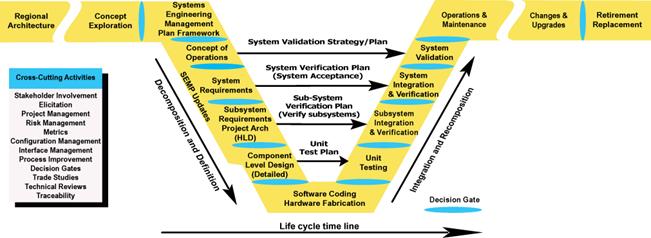
Figure 3-4 Adapted from the Vee Technical Development Model
Basic Terms and Definitions
Architecture: Two definitions [1] A regional ITS architecture is a specific, tailored framework for ensuring institutional agreement and technical integration for the implementation of ITS projects or groups of projects in a particular region. It functionally defines what pieces of the system are linked to others and what information is exchanged between them.[2] A project architecture is a project-specific description of both logical and physical elements arranged in a hierarchical form showing inter-connections among the elements. It has enough definition that component level detailed design specifications can be written and developed.
System: An integrated composite of people, products, and processes which provide a capability to satisfy a stated need or objective.
Systems Engineering: An inter-disciplinary approach and a means to enable the realization of successful systems. Systems engineering requires a broad knowledge, a mindset that keeps the big picture in mind, a facilitator, and a skilled conductor of a team.
FHWA Final Rule: The FHWA Rule on Architecture Standards and Conformity [Final Rule], also referred to as 23 CFR 940, requires that regional ITS architectures and all ITS projects using Federal funds be developed using a systems engineering analysis. The systems engineering analysis includes: identification of the portion of the RA being implemented, participating agencies roles and responsibilities, requirements definition, alternatives analysis, procurement options, identification of applicable ITS standards and testing procedures, and procedures and resources for system operations and management.
Chapter 3.2.1 to 3.8.1 Process Activities
The following is a summary of the process steps in the Vee technical model.
Interfacing with Planning and the regional ITS architecture [ 3.2.1]
This initial step interfaces with the ITS architecture for a region. Development of a regional ITS architecture is not covered by this Guidebook since it is well described in the Regional ITS Architecture Guidance Document. Key activities of this phase are: 1] the identification of the regional stakeholders and 2] the building of consensus for the purposes of information sharing and long term operations & maintenance. The architecture is coordinated with the long range transportation plan and candidate ITS projects are programmed through the Transportation Improvement Program, Statewide Transportation Improvement Program, and agency capital plans. For more information on developing a regional ITS architecture please refer to Regional ITS Architecture Guidance Document at: http://www.its.dot.gov/research_archives/arch/.
Needs Assessment, Concept Exploration & Benefits Analysis [3.3.1 & 3.3.2]
Concept Exploration is used to perform an initial feasibility & benefits analysis and needs assessment for the candidate projects from the regional ITS architecture. This results in a business case and specific cost benefit analyses for alternative project concepts. The output of this stage is a definition of the problem space, key technical metrics, and refinements to the needs, goals, objectives, and vision. This stage identifies the highest cost/benefit concept [best business case] project to move forward into development. This activity may result in combining or dividing candidate projects based on the best cost/benefit analysis. The decision gate is to gain management support & approval for the project to move into the planning and definition phases of the project.
Systems Engineering Planning [3.4.1 & 3.4.2]
Each project that moves forward into development must be planned. Planning takes place in two parts. In part one, the system’s owner develops a set of master plans and schedules that identifies what plans are needed and, at a high level, the schedule for implementation of the project. This becomes the framework for what is developed in part two. In part two, the plans are completed during the steps from the concept of operations to the high level design. These plans, once approved by the system’s owner, become the control documents for completion of the development and implementation of the project.
Concept of Operations [3.4.3]
Concept of Operations is the initial definition of the system. At this stage, the project team documents the way the envisioned system is to operate and how the envisioned system will meet the needs and expectations of the stakeholders. The envisioned operation is defined from multiple viewpoints consisting of operators, maintainers, and managers. The focus is on how the system will be validated [proof that the envisioned system meets the intended needs]. A refinement of the problem space, definition, needs, goals, expectations, stakeholder lists, and project constraints is placed into the concept of operations document. This document contains the updated, refined summary of work done at the concept exploration phase.
System Level Requirements [3.5.1]
Requirements are developed for the system. At the system level; the definition of what the system is to do, how well it is to do it, and under what conditionsisdocumented. System requirements are based on the user needs from the Concept of Operations. Requirements do not state how [design statements] the system will be implemented unless it is intended to constrain the development team to a specific solution.
High Level Design [Project Architecture] and Sub-system Requirements [ 3.5.2]
The High Level Design stage defines the project level architecture for the system. System level requirements are further refined and allocated [assigned] to the sub-systems of hardware, software, databases, and people.
Requirements for each sub-system element are documented the same way as the system level requirements. This process is repeated until the system is fully defined and decomposed. Each layer will have its own set of interfaces defined. Each layer will require an integration step that is needed when the sub-system is developed. The control gate that is used for this final review is sometimes called the Preliminary Design Review [PDR].
Component Level Detailed Design [ 3.5.3]
At the Component Level Detailed Design step the development team defines how the system will be built. Each sub-system has been decomposed into components of hardware, software, database elements, firmware, and/or processes. For these components, Detailed Design specialists in the respective fields create documentation [“build-to” specifications] which will be used to build or procure the individual components. A final check is done on the “build–to” specifications before the design moves forward to the actual coding and hardware fabrication. At this level, the specific commercial off-the-shelf [COTS] hardware and software products are specified. They are not purchased until the review is completed and approved by the system’s owner and stakeholders. The control gate used for this final review is sometimes called the Critical Design Review [CDR].
Hardware/Software Procurement or Development and Unit Test [3.6.1]
This stage involves hardware fabrication, software coding, database implementation, and the procurement & configuration of COTS products. This stage is primarily the work of the development team. The system’s owner and stakeholders monitor this process with planned periodic reviews, e.g. code walkthroughs and technical review meetings. Concurrent with this effort, unit test procedures are developed that will be used to demonstrate how the products will meet the detailed design. At the completion of this stage, the developed products are ready for unit test.
Unit Testing [3.6.1]
The components from the hardware and software development are verified in accordance with the unit Verification Plan. The purpose of unit testing is to verify that the delivered components match the documented Component Level Detailed Design. This is done by the development team in preparation for the next level of integration. It is also a good review point for the system’s owner and stakeholders.
Sub-system Integration and Verification [ 3.6.2, 3.6.3]
At this step, the components are integrated and verified at the lowest level of the sub-systems. The first level of verification is done in accordance with the Verification Plan and is carried out in accordance with the Verification Procedures [step-by-step method for carrying out the verification] developed in this stage. Prior to the actual verification, a Test Readiness Review is held to determine the readiness of the sub-systems for verification. When it has been determined that verification can proceed, the sub-systems are then verified. When the integration and verification is completed, the next level of sub-system is integrated and verified in the same manner. This process continues until all sub-systems are integrated and verified.
System Verification [ 3.6.3]
System Verification is done in two parts. The first part is done under a controlled environment [sometimes called a “factory test”]. The second part is done within the environment that the system is intended to operate [sometimes called “on-site testing/verification”] after initial system deployment. At this stage, the system is verified in accordance with the Verification Plan developed as part of the system level requirements performed early in the development. The system acceptance will continue through the next stage, Initial System Deployment. The final part of System Verification is then completed. A control gate is used for this conditional system acceptance.
Initial System Deployment [ 3.6.4]
At Initial System Deployment, the system is finally integrated into its intended operational environment. This step may take several weeks to complete to ensure that the system operates satisfactorily in the long term. This is sometimes called a “system burn-in”. Many system issues surface when the system is operating in the real world environment for an extended period of time. This is due to the uncontrollable nature of inputs to the system, such as long term “memory” leaks in software coding and race conditions [unexpected delays between signals] that may only occur under specific and infrequent conditions. Once the System Verification is completed, the system is accepted by the system’s owner and stakeholders and then moves into the System Validation and Operations & Maintenance phases.
System Validation [ 3.7.1]
Validating the system is a key activity of the system’s owner and stakeholders. It is here that they will assess the system’s performance against the intended needs, goals, and expectations documented in the Concept of Operations and the Validation Plan. It is important that this validation takes place as early as possible [after the acceptance of the system] in order to assess its strengths, weaknesses, and new opportunities. This activity does not check on the work of the system integrator or the component supplier [that is the role of System Verification]. It is performed after the system has been accepted and paid for. As a result of validation, new needs and requirements may be identified. This evaluation sets the stage for the next evolution of the system.
Operations & Maintenance [3.7.2]
After the initial deployment and system acceptance, the system moves into the Operations & Maintenance phase. In this phase the system will carry out the intended operations for which it was designed. During this phase routine maintenance is performed as well as staff training. This phase is the longest phase, extending through the evolution of the system and ends when the system is retired or replaced. This phase may continue for decades. It is important that there are adequate resources to carry out the needed Operations & Maintenance activities; otherwise, the life of the system could be significantly shortened due to neglect.
Changes & Upgrades [3.7.3]
Changes & Upgrades should be implemented in accordance with the Vee technical process recommended by this Guidebook. Using the Vee process for changes & upgrades will help maintain system integrity [synchronization between the system components and supporting documentation]. When the existing system is not well documented, start by reverse engineering the affected area of the system in order to develop the needed documentation for the forward engineering process.
Retirement/Replacement [3.8.1]
Eventually, every ITS system will be retired or replaced for one of the following reasons:
This phase looks at how to monitor, assess needed changes, and make change/upgrade decisions.
Cross-Cutting Activities [3.9]
A number of cross-cutting activities are needed to support the development of Intelligent Transportation Systems. The following are the enabling activities used to support one or more of the life-cycle process steps.
Stakeholder Involvement [ 3.9.1]
Stakeholder involvement is regarded as one of the most critical enablers within the development and life-cycle of the project and system. Without effective stakeholder involvement, the systems engineering and development team will not gain the insight needed to understand the key issues and needs of the system’s owner and stakeholders. This increases the risk of not getting a valid set of requirements to build the system or to obtain buy-in on changes & upgrades.
Elicitation [ 3.9.2]
Elicitation is an activity that when performed correctly, effectively, and accurately, gathers and documents information needed to develop the system. The typical types of information include needs, goals, objectives, requirements, and stakeholder expectations. Some information may be in a documented form or stated clearly by the stakeholders, but much of the needed information may be implied or assumed. The elicitation processes help draw out and resolve this information, resolve conflicting information, build consensus, and validate the information.
Project Management Practices [ 3.9.3]
Various project management practices are needed to support the development of the system. Project management practices provide a supportive environment for the various development activities. It provides the needed resources, then monitors and controls costs and schedules. It also communicates status between and across the development team members, system’s owner, and stakeholders.
Risk Management [ 3.9.4]
There will be risks for ITS system development efforts. Risk Management is a process used to identify, analyze, plan, and monitor risk. Then, it mitigates, avoids, transfers, or accepts those risks.
Project Metrics [ 3.9.5]
Project metrics are measures that are used by both the project manager and systems engineer to track and monitor the project and the expected technical performance of the system development effort. The identification and monitoring of metrics allow the team to determine if the project is “on-track” both programmatically and technically.
Configuration Management [ 3.9.6]
Managing change to the system is a key process that occurs throughout the life of the system. Configuration management is the process that supports the establishment of system integrity [the documentation matches the functional and physical attributes of the system]. It maintains this integrity throughout the life of the system [synchronizes changes to the system with its documentation]. A lack of change management will shorten the life of the system and may prevent a system from being implemented and deployed.
Process Improvement [3.9.7]
A quality aspect of the system’s life cycle is to continuously improve the process. This is done by learning from previous efforts how to improve future work. Process Improvement is an enabler that provides insight about what worked and what needs improvement in the processes. This activity is used to improve the documented processes over time.
Decision Gates [ 3.9.8]
Decision Gates are formal decision points along the life cycle that are used by the system’s owner and stakeholders to determine if the current phase of work has been completed and if the team is ready to move onto the next phase of the life cycle. By setting entrance and exit criteria for each phase of work, the control gates are used to review and accept the work products done for the current phase of work. They also evaluate the readiness for moving to the next phase of the project.
Decision Support/Trade Studies [ 3.9.9]
Technical decisions on alternative solutions are a key enabler for each phase of system development. This starts when alternative concepts are evaluated and continues through the system definition and design phases. This chapter provides a method to perform a trade study.
Technical Reviews [ 3.9.10]
Technical reviews are used to assess the completeness of a product, identify defects in work, and align team members in a common technical direction. This chapter provides a process for conducting a technical review.
Traceability [ 3.9.11]
Traceability is a key cross-cutting process that supports verification & validation of requirements by ensuring that all needs are traced to requirements and that all requirements are implemented, verified, and validated. Traceability supports impact analysis for changes, upgrades, and replacement.
Key Observations for the Vee
Development Model
Some Basic Systems Engineering Principles
The Systems Engineer should have the following mindset when developing a system:
1. View the system from the stakeholder point of view [walk in the shoes of the system’s owner and stakeholders]. Key processes include needs assessment, elicitation, Concept of Operations, and stakeholder involvement.
2. Start at the finish line to define the output of the system and the way the system is going to operate. Key processes include Concept of Operations and Validation Plan.
3. Address risks as early as possible when the cost impacts are lowest. Key processes include risk management, requirements, and stakeholder involvement [spend more time on the left side of the Vee].
4. Push technology choices to the last possible moment. Define what is to be done before defining how it is to be done [form follows function].
5. Focus on interfaces of the system during the definition of the system. Defining clear and standard interfaces and managing them through the development will ease the integration of the individual elements of the system.
6. Understand the organization of the system’s owner, stakeholders, and development team.
Phases, Tasks, Activities and Products
Table 3-1 to Table 3‑5 provide an overview of the typical tasks, activities products, and decision gates that are associated with each phase of the development life cycle.
Table 311 Phase [-1] & 0 Tasks, Activities Products, Decision Gates
| Phase | Phase [-1] Regional Architecture |
Phase 0 Concept Exploration |
|
|---|---|---|---|
| Chapter | 3.2.1 | 3.3.1 | 3.3.2 |
| Tasks |
|||
| Activities |
|
|
|
| Products |
|
|
|
|
|
|
|
Table 3-2 Phase 1 Tasks, Activities, Products, Decision Gates
| Phase |
Phase 1 |
||
|---|---|---|---|
| Chapter |
3.4.1 |
3.4.2 |
3.4.3 |
| Tasks |
|||
| Activities |
|
|
|
| Products |
|
|
|
· Project Plan |
|
||
Table 3-3 Phase 2 Tasks, Activities, Products, Decision Gates
| Phase | Phase 2 System Definition and Design |
||
|---|---|---|---|
| Chapter | 3.5. | 3.5.2 | 3.5.3 |
| Tasks | Requirements Development | High Level Design | Component Level Detailed Design> |
| Activities |
|
· Develop, decompose, and evaluate project level architecture alternatives · Identify and evaluate internal and external interfaces · Evaluate industry standards · Select & document the high level design · Perform preliminary design review |
· Evaluate COTS commercial off the shelf products and applications · Perform detailed design · Perform technical reviews · Perform critical design review |
| Products |
· System and sub-system requirements document · Verification Plan |
· High level design document · Internal and external interfaces · Select appropriate industry standards · Sub system verification plans |
· Selected COTS products · Component detailed design document · Unit Verification Plan |
| Decision Gates |
· System Requirements |
· Sub systems requirements |
· Detailed design |
Table 3‑4 Phase 3 Tasks, Activities, Products, Decision Gates
| Phase |
Phase 3 System Development & Implementation |
|||
|---|---|---|---|---|
| Chapter |
3.6.1 |
3.6.2 |
3.6.3 |
3.6.4 |
| Tasks |
||||
| Activities |
|
|
|
|
| Products |
|
|
|
|
|
· Verification Readiness |
· Acceptance of sub-system products |
· Acceptance of System |
|
Table 3-5 Phase 4 & 5 Tasks, Activities, Products, Decision Gates
| Phase |
Phase 4 Changes & Upgrades |
Phase 5 Retirement/ Replacement |
||
|---|---|---|---|---|
| Chapter |
3.7.1 |
3.7.2 |
3.7.3 |
3.8.1 |
| Tasks |
||||
| Activities |
· Develop Validation Strategy · Plan Validation · Validate system |
· Plan O&M · Collect O&M information · Perform O&M |
|
|
| Products |
· Validation Master Plan · Validation Plan · Validate system · Validation report |
· O&M plan · Improved O&M · Updated O&M procedures · Requirements for next evolution |
· Documented legacy systems · Updated system products and documentation |
|
|
|
|
· Retirement / Replacement |
|

