U.S. Department of Transportation
Federal Highway Administration
1200 New Jersey Avenue, SE
Washington, DC 20590
202-366-4000
California Division

The ITS Project Life cycle on the following pages shows the entire set of systems engineering tasks required for an ITS project. All of these are described in detail in this Guidebook.
The entire sequence of systems engineering tasks is grouped into six phases [0 through 5], covering everything from the initial concept exploration to the final system retirement. Each phase includes from one to four tasks. Each task is described according to its major activities, primary products, and control gates. The chapter number in this Guidebook identifies each task.
Sequence of Phases, Tasks, and Activities
Each of the ITS Project Life cycle phases described in this Guidebook require a specific set of management and engineering skills. In large system development projects, activities within each task may be performed by a different set of people. For most ITS projects, this is not the case. The same individuals may perform several, or even all, of the activities within a task.
For these reasons, the phases and tasks in this Guidebook are to be performed sequentially, especially for phases 1 and 2. In these early phases, there is a temptation to start the next task prior to the completion and acceptance by the stakeholders of the current task, this is sometimes called concurrent engineering. For ITS, depending on the complexity of the project this decision to move forward prior to completing a previous phase must be done with great care and in some cases it is not recommended. It might appear that overlapping the tasks can shorten the schedule. But, this introduces significant risks into the project. For example, starting the high level design prior to the development and acceptance of the system level requirements introduces the risk of reworking both. Or worse, the team moves on to detailed design prior to completing either of the previous phases. Within each task, the activities are designed to work together to meet the objectives of that part of work. In some cases, similar activities can show up in different tasks or even phases. For example, prototyping is a primary activity of the detailed design task. Also, prototyping is often done at the concept of operations and requirement development stage to ensure the feasibility of the concept or requirements and to validate concepts and requirements to the stakeholders.
Relative Durations of System Development Tasks
The following discussion only considers the duration of the system development activities. That includes the phases following Concept Exploration; culminating in Operations & Maintenance. System development refers to phases 1, 2, and 3 as illustrated in Figure 3‑5. A detailed list of tasks, activities, products, and control gates is located in this chapter. Tasks performed before and after system development are subject to too great of variation [both for institutional and operations reasons] to make any generalizations on their duration meaningful.
Roughly speaking, phase 1 [Project Planning and Concept of Operations] takes about 10% of the total project duration, phase 2 [System Definition] about 30%, phase 3 [System Development and Implementation] about 50% and on going project management approximately 10%.
These relative levels of duration are useful as a rule-of-thumb or a reality check. The duration of every individual project must eventually be estimated on a bottom-up basis. That is, each individual task must be described in an appropriate level of detail. Then the time required for each task must be estimated based on the complexity of the individual task within the context of the specific project. Only then can a reasonably realistic schedule for a project be compiled.
The following is a detailed look at each of the phases, inputs, outputs, enablers, and controls for each activity.
Phase [-1]: Figure 3‑6 Phase [-1] - Interfacing with the Regional Architecture
Phase 0: Figure 3‑7 Phase 0 - Concept Exploration and Benefits Analysis Roadmap
Phase 1: Figure 3‑8 Phase 1 - Project Planning and Concept of Operations Development Roadmap
Phase 2: Figure 3‑9 Phase 2 - System Definition Roadmap
Phase 3: Figure 3‑11 Phase 3 - System Development and Implementation Roadmap
Phase 4: Figure 3‑14 Phase 4 - Validation, O&M, Changes & Upgrades Roadmap
Phase 5: Figure 3‑15 Phase 5 - System Retirement and/or Replacement Roadmap
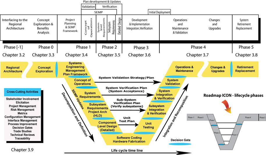
Figure 3-5 Roadmap through Chapter 3 of the Guidebook

