

| << Previous | Contents | Next >> |
Geotechnical Aspects of Pavements Reference Manual
Chapter 5.0 Geotechnical Inputs For Pavement Design (continued)
5.4.5 Structural Layer Coefficients
The material quality of granular base and subbase layers is characterized in the AASHTO flexible pavement design procedures in terms of structural layer coefficients ai (see Section 3.5.2). These coefficients were entirely empirical through the 1972 version of the Guide. Beginning with the 1986 Guide, the recommended procedure for estimating structural layer coefficients is through correlations with resilient modulus.
It must be emphasized that structural layer coefficients are not fundamental engineering properties for a material. There are no laboratory or field procedures for measuring structural layer coefficients directly. The structural layer coefficients were originally defined as simple substitution ratios - i.e., how much additional thickness of granular base at a given reference stiffness must be added if a unit thickness of asphalt concrete of a given stiffness is removed in order to maintain the same surface deflection under a standardized load? These substitution ratios were evaluated in the 1986 AASHTO Guide1 via a parametric analytical study for a limited range of flexible pavement geometries and layer stiffnesses. In this approach, the value of the structural layer coefficient for a given material also depends not only on its inherent stiffness, but also upon the material's location within the pavement structure (e.g., the a2 value for a given material when used in a base layer is different from the a3 value for that same material when used as a subbase). Subsequent correlations between structural layer coefficients and other engineering properties such as resilient modulus and CBR are entirely empirical. Structural layer coefficients are not used in mechanistic-empirical design procedures like the NCHRP 1-37A Design Guide.
New Construction/Reconstruction
The relationship in the 1993 AASHTO Guide between the structural layer coefficient a2 and resilient modulus EBS (in psi) for granular base materials is given as:
(5.16)a2 = 0.249 log10 EBS - 0.977
The value for EBS in Eq. (5.16) will be a function of the stress state within the layer. The relationship suggested in the 1993 AASHTO Guide is:
(5.17)EBS = k1 θk2
in which
| θ | = | sum of principal stresses = σ1 + σ2 + σ3 (psi) |
| k1, k2 | = | material properties |
Typical values for the material properties are (see also Table 5-39):
| k1 | = | 3000 to 8000 psi |
| k2 | = | 0.5 to 0.7 |
The values of EBS from the base layers in the original AASHO Road Test are summarized in Table 5-40. Note that the EBS values are not only functions of moisture, but also of stress state θ, which in turn is a function of the pavement structure - i.e., subgrade modulus and thickness of the surface layer. Typical values of θ recommended in the 1993 AASHTO Guide for use in base design are summarized in Table 5-41.
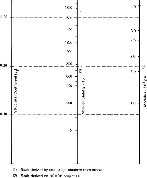
Figure 5-19 summarizes correlations between the a2 structural layer coefficient for nonstabilized granular base layers and corresponding values of CBR, R-Value, Texas triaxial strength, and resilient modulus. Similar correlations between a2 and various strength and stiffness measures for cement- and bituminous-treated granular bases are given in Figure 5-20 and Figure 5-21.
Figure 5-19. Correlations between structural layer coefficient a2 and various strength and stiffness parameters for unbound granular bases (AASHTO, 1993).
Click here to view text version of image
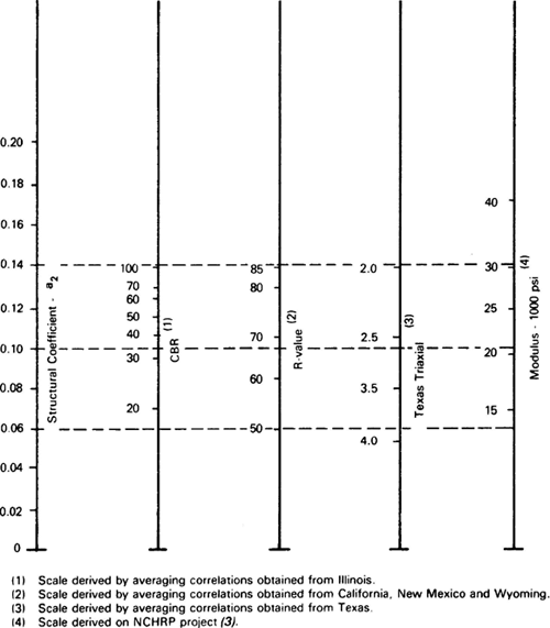
Figure 5-20. Correlations between structural layer coefficient a2 and various strength and stiffness parameters for cement-treated granular bases (AASHTO, 1993).
Click here to view text version of image
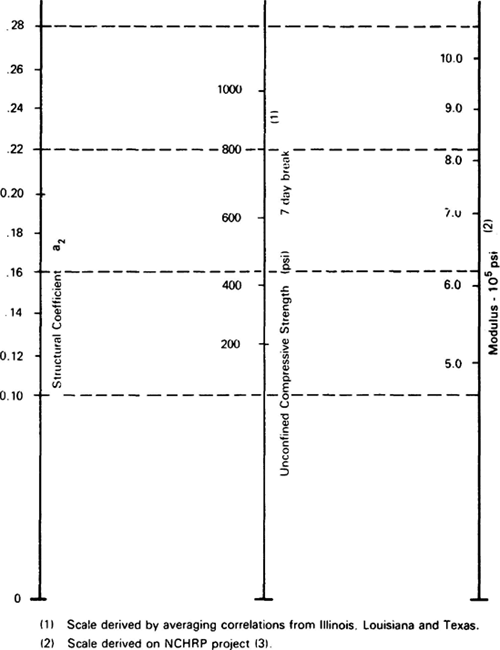
Figure 5-21. Correlations between structural layer coefficient a2 and various strength and stiffness parameters for bituminous-treated granular bases (AASHTO, 1993).
Click here to view text version of image
| Moisture Condition | k1* (psi)** | k2* |
|---|---|---|
| (a) Base | ||
| Dry | 6,000 - 10,000 | 0.5 - 0.7 |
| Damp | 4,000 - 6,000 | 0.5 - 0.7 |
| Wet | 2,000 - 4,000 | 0.5 - 0.7 |
| (b) Subbase | ||
| Dry | 6,000 - 8,000 | 0.4 - 0.6 |
| Damp | 4,000 - 6,000 | 0.4 - 0.6 |
| Wet | 1,500 - 4,000 | 0.4 - 0.6 |
- *Range in k1 and k2 is a function of the material quality
- **1 psi = 6.9 kPa
| Moisture State | Equation | Stress State (psi*) | |||
|---|---|---|---|---|---|
| θ = 5 | θ = 10 | θ = 20 | θ = 30 | ||
| Dry | 8,000 θ0.6 | 21,012 | 31,848 | 48,273 | 61,569 |
| Damp | 4,000 θ0.6 | 10,506 | 15,924 | 24,136 | 30,784 |
| Wet | 3,200 θ0.6 | 8,404 | 12,739 | 19,309 | 24,627 |
*1 psi = 6.9 kPa
| Asphalt Concrete Thickness (inches*) | Roadbed Soil Resilient Modulus (psi*) | ||
|---|---|---|---|
| 3,000 | 7,500 | 15,000 | |
| < 2 | 20 | 25 | 30 |
| 2 - 4 | 10 | 15 | 20 |
| 4 - 6 | 5 | 10 | 15 |
| > 6 | 5 | 5 | 5 |
*1 inch = 25.4 mm; 1 psi = 6.9 kPa
The relationship in the 1993 AASHTO Guide between the structural layer coefficient a3 and resilient modulus ESB (in psi) for granular subbase materials is given as:
(5.18)a3 = 0.227 log10 ESB - 0.839
The resilient modulus ESB for granular subbase layers is influenced by stress state in a manner similar to that for the base layer, as given in Eq. (5.17). Typical values for the k1 and k2 material properties for granular subbases are:
- k1 = 1500 to 6000
- k2 = 0.4 to 0.6
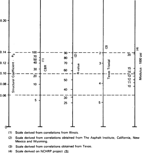
The values of ESB from subbase layers in the original AASHO Road Test are summarized in Table 5-42. Note that the ESB values are not only functions of moisture, but also of stress state θ, which in turn is a function of the pavement structure - i.e., thickness of the asphalt concrete surface layer. Typical values of θ recommended in the 1993 AASHTO Guide for use in subbase design are summarized in Table 5-43. Figure 5-22 summarizes relationships between the a3 structural layer coefficient for granular subbase layers and corresponding values of CBR, R-Value, Texas Triaxial strength, and resilient modulus.
| Moisture State | Equation | Stress State (psi*) | ||
|---|---|---|---|---|
| θ = 5 | θ = 7.5 | θ = 10 | ||
| Damp | 5,400 θ0.6 | 14,183 | 18,090 | 21,497 |
| Wet | 4,600 θ0.6 | 12,082 | 15,410 | 18,312 |
*1 psi = 6.9 kPa
| Asphalt Concrete Thickness (inches*) | Stress State (psi*) |
|---|---|
| < 2 | 10.0 |
| 2 - 4 | 7.5 |
| > 4 | 4.0 |
*1 inch = 25.4 mm; 1 psi = 6.9 kPa
Figure 5-22. Correlations between structural layer coefficient a3 and various strength and stiffness parameters for unbound granular subbases (AASHTO, 1993).
Click here to view text version of image
Rehabilitation
Depending on the types and amounts of deterioration present, the layer coefficient values assigned to materials in in-service existing pavements should in most cases be less than the values that would be assigned to the same materials for new construction. Exceptions to this general rule would include unbound granular materials that show no sign of degradation or contamination.
Limited guidance is available for the selection of layer coefficients for in-service pavement materials. Recommendations from the 1993 AASHTO Pavement Design Guide are provided in Table 5-44. In addition to evidence of pumping noted during a visual condition survey, samples of base and subbase materials should be obtained and examined for evidence of erosion, degradation, and contamination by fines, as well as evaluated for drainability, and layer coefficients should be reduced accordingly. Coring and testing are recommended for evaluation of all materials and are strongly recommended for evaluation of stabilized layers.
| Material | Surface Condition | Coefficient |
|---|---|---|
| AC Surface | Little or no alligator cracking and/or only low-severity transverse cracking | 0.35 - 0.40 |
| <10% low-severity alligator cracking and/or <5% medium- and high-severity transverse cracking | 0.25 - 0.35 | |
| >10% low-severity alligator cracking and/or <10 percent medium-severity alligator cracking and/or >5-10% medium- and high-severity transverse cracking | 0.20 - 0.30 | |
| >10% medium-severity alligator cracking and/or <10% high-severity alligator cracking and/or >10% medium- and high-severity transverse cracking | 0.14 - 0.20 | |
| >10% high-severity alligator cracking and/or >10% high-severity transverse cracking | 0.08 - 0.15 | |
| Stabilized Base | Little or no alligator cracking and/or only low-severity transverse cracking | 0.20 - 0.35 |
| <10% low-severity alligator cracking and/or <5% medium- and high-severity transverse cracking | 0.15 - 0.25 | |
| >10% low-severity alligator cracking and/or <10% medium-severity alligator cracking and/or >5-10% medium- and high-severity transverse cracking | 0.15 - 0.20 | |
| >10% medium-severity alligator cracking and/or <10% high-severity alligator cracking and/or >10% medium- and high-severity transverse cracking | 0.10 - 0.20 | |
| >10% high-severity alligator cracking and/or >10% high-severity transverse cracking | 0.08 - 0.15 | |
| Granular Base/Subbase | No evidence of pumping, degradation, or contamination by fines | 0.10 - 0.14 |
| Some evidence of pumping, degradation, or contamination by fines | 0.00 - 0.10 |
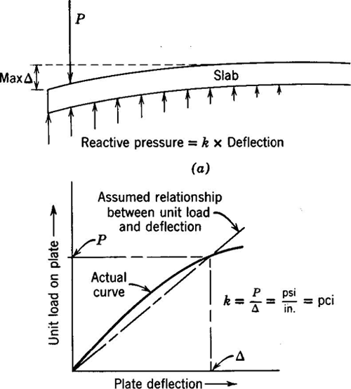
5.4.6 Modulus of Subgrade Reaction
Mechanistic solutions for the stresses and strains in rigid pavements have historically characterized the stiffness of the foundation soil in terms of the modulus of subgrade reaction k (Figure 5-23). However, the modulus of subgrade reaction is not a true engineering property for the foundation soil because it depends not only upon the soil stiffness, but also upon the slab (or footing) size and stiffness. For an example of a square footing on a homogeneous isotropic elastic foundation soil, k can be expressed as:
(5.19)| k = | 0.65 E | EB4 | |
| B ( 1 - ν2 ) | Ef I |
in which
| B | = | width of footing |
| E | = | elastic modulus of soil |
| ν | = | Poisson's ratio of soil |
| Ef | = | elastic modulus of footing |
| I | = | moment of inertia of footing = Bt3 / 12, t = footing thickness |
For a given slab/footing size and stiffness, k is directly proportional to the effective elastic modulus of the foundation soil in Eq. (5.19).
The effective modulus of subgrade reaction is a direct input in the AASHTO design procedures for rigid pavements (see Section 3.5.2). The modulus of subgrade reaction was first introduced in the 1972 version of the Guide, with the recommendation that its value be determined from plate loading tests. Beginning with the 1986 Guide, the recommended procedure for estimating k for new/reconstruction designs is through correlations with subgrade MR plus various adjustments for base layer stiffness and thickness, presence of shallow rock, potential loss of slab support due to erosion, and seasonal variations2. The recommended procedure for determining k for rehabilitation designs is backcalculation from FWD test results.
Figure 5-23. Coefficient of subgrade reaction k (Yoder and Witczak, 1975).
The subgrade, base, and subbase resilient moduli values are the direct inputs in the NCHRP 1-37A design methodology. These values are adjusted internally within the NCHRP 1-37A Design Guide software for environmental effects and then converted into an average monthly effective k-value for structural response calculation and damage analysis.
The detailed procedures used in the 1993 AASHTO and NCHRP 1-37A Design Guides to determine k for new/reconstruction and rehabilitation designs are described in the following subsections.
1993 AASHTO Guide
New Construction/Reconstruction
The steps recommended in the 1993 AASHTO Design Guide for determining the effective modulus of subgrade reaction for new/reconstruction designs are as follows:
- Identify the subgrade and subbase type(s), thicknesses, and other properties.
- Determine the subgrade resilient modulus MR values for each season. Appropriate techniques for this are similar to those described earlier in Section 5.4.3.
- Determine the subbase3 resilient modulus ESB for each season (similar to step 2). The 1993 AASHTO Guide recommends the following limits for the subbase resilient modulus:
(5.20)
15,000 (spring thaw) < ESB (psi) < 50,000 (winter freeze)
(5.21)ESB < 4 MR (psi)
- Using Figure 5-24, determine a composite k value for each season that represents the combined stiffness of the subgrade and subbase. Figure 5-24 is based on the following model (see Appendix LL in Volume 2 of AASHTO, 1986):
(5.22)
ln k∞ = -2.807 + 0.1253 ( ln DSB )2 + 1.062 ( ln MR ) + 0.1282 ( ln DSB ) ( ln ESB ) - 0.4114 ( ln DSB ) - 0.0581 ( ln ESB ) - 0.1317 ( ln DSB ) ( ln MR ) in which
k∞ = composite modulus of subgrade reaction (pci) assuming a semi-infinite roadbed soil DSB = subbase thickness (inches) ESB = subbase elastic modulus (psi) MR = subgrade resilient modulus (psi) - Using Figure 5-25, correct the composite k values from step 4 for any effects of shallow bedrock. Figure 5-25 is based on the following model (see Appendix LL in Volume 2 of AASHTO, 1986):
(5.23)
ln krf = 5.303 + 0.0710 ( ln DSB ) ( ln MR ) + 1.366 ( ln k∞ ) - 0.9187 ( ln DSG ) - 0.6837 ( ln MR ) in which
krf = composite modulus of subgrade reaction (pci) considering the effect of a rigid foundation near the surface DSG = depth to rigid foundation (inches) and the other terms are as defined previously in Eq. (5.22).
- Determine the seasonal average composite k value using the following procedure:
- Estimate the design thickness of the slab and use Figure 5-26 to determine the relative damage uri for each season. Figure 5-26 is based on the following simplified damage model (see Appendix HH in Volume 2 of AASHTO, 1986):
(5.24)
uri = [ D0.75 - 0.39 ki0.25 ]3.42
in which D is the slab thickness (inches) and ki is the modulus of subgrade reaction for each season.
- Compute the average relative damage u as the sum of the relative damage values for each season divided by the number of seasons.
- Determine the seasonally averaged composite k from Figure 5-26 using u and the estimated slab thickness. This seasonally averaged composite k is termed the effective modulus of subgrade reaction keff.
- Estimate the design thickness of the slab and use Figure 5-26 to determine the relative damage uri for each season. Figure 5-26 is based on the following simplified damage model (see Appendix HH in Volume 2 of AASHTO, 1986):
(5.24)
- Using Figure 5-27 and Table 5-45, correct the effective modulus of subgrade reaction keff for loss of support due to subbase erosion. This corrected keff is the value to be used for design. Table 5-46 summarizes the recommended design values for the modulus of subgrade reaction from the low-volume road section of the 1993 Design Guide.
Figure 5-24. Chart for estimating composite modulus of subgrade reaction k∞, assuming a semi-infinite subgrade depth (AASHTO, 1993).
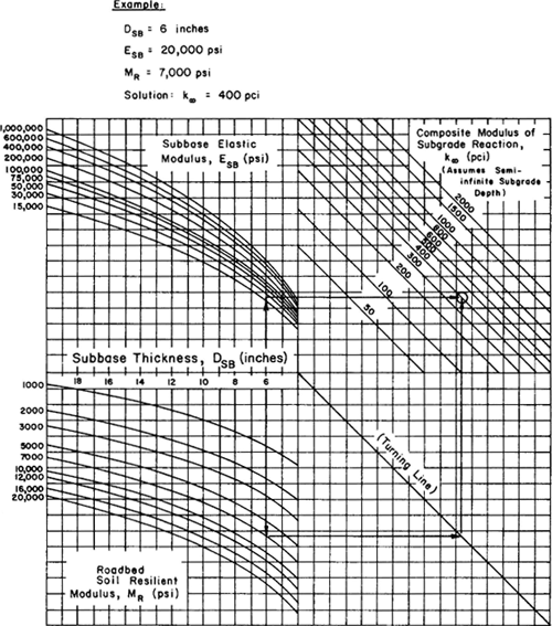
Figure 5-25. Chart to modify modulus of subgrade reaction to consider effects of rigid foundation near surface (within 10 ft) (AASHTO, 1993).
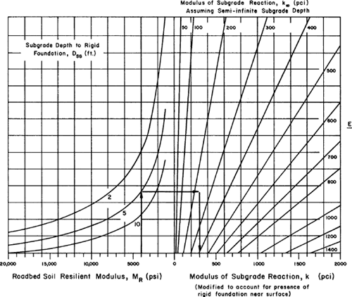
Figure 5-26. Chart for estimating relative damage to rigid pavements based on slab thickness and underlying support (AASHTO, 1993).
![GRAPH: Graph of the model contained in Equation 5.24: {u sub ri equals [ D to the three-quarters power minus 0.39 times k to the one-quarter power] to the 3.42 power}](images/f073.gif)
Figure 5-27. Correction of effective modulus of subgrade reaction for potential loss of subbase support (AASHTO, 1993).
Click here for text version of image
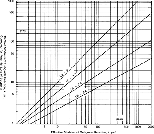
| Type of Material | Loss of Support (LS) |
|---|---|
| Cement treated granular base (E = 1,000,000 to 2,000,000 psi) | 0.0 to 1.0 |
| Cement aggregate mixtures (E = 500,000 to 1,000,000 psi) | 0.0 to 1.0 |
| Asphalt treated base (E = 350,000 to 1,000,000 psi) | 0.0 to 1.0 |
| Bituminous stabilized mixtures (E = 40,000 to 300,000 psi) | 0.0 to 1.0 |
| Lime stabilized (E = 20,000 to 70,000) | 1.0 to 3.0 |
| Unbound granular materials (E = 15,000 to 45,000 psi) | 1.0 to 3.0 |
| Fine grained or natural subgrade materials (E = 3,000 to 40,000 psi) | 2.0 to 3.0 |
| Roadbed Soil Quality | Range for keff (pci) |
|---|---|
| Very Good | > 550 |
| Good | 400 - 500 |
| Fair | 250 - 350 |
| Poor | 150 - 250 |
| Very Poor | < 150 |
Rehabilitation
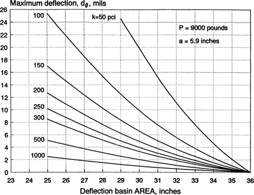
For rehabilitation projects, the modulus of subgrade reaction k can be determined from FWD deflection testing of the existing PCC pavement. An FWD with a load plate radius of 5.9 inches and a load magnitude of 9000 pounds is recommended, with deflections measured at sensors located at 0, 12, 24, and 36 inches from the center of the load along the outer wheel path. For each slab tested, a dynamic kdynamic value (pci) can be determined from Figure 5-28 based on the deflection at the center of the loading plate, d0 (inches) and the AREA of the deflection basin as computed by4:
(5.25)| AREA = 6 | 1 + 2 | d12 | + 2 | d24 | + | d36 | ||||||||
| d0 | d0 | d0 |
in which the di values are the deflections at i inches from the plate center. The static keff value for design is then determined as:
(5.26)| keff = | kdynamic |
| 2 |
As is the case for new/reconstruction, this keff value may need to be adjusted for seasonal effects.
Figure 5-28. Effective dynamic k value determination from d0 and AREA (AASHTO, 1993).
Click here for text version of image
NCHRP 1-37A Design Guide
New Construction/Reconstruction
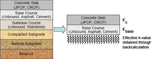
All subgrade and unbound pavement layers for all pavement types are characterized using MR in the NCHRP 1-37A design methodology. The pavement response model for rigid pavement design, however, is based on a Winkler-spring foundation model that requires a value for the modulus of subgrade reaction kdynamic (see Appendix D for more details on the rigid pavement response model). The modulus of subgrade reaction is obtained from the subgrade and subbase MR values and the subbase thickness through a conversion process that transforms the actual multilayer pavement structure into an equivalent three-layer structure consisting of the PCC slab, base, and an effective dynamic k, as shown in Figure 5-29. This conversion is performed internally in the NCHRP 1-37A Design Guide software as a part of input processing.
The procedure to obtain the effective value of kdynamic for each time increment in the analysis can be summarized in the following steps:
- Assign initial estimates of the stiffness parameters MR and n to each unbound layer in the pavement structure.
- Using multilayer elastic theory, simulate an FWD load and compute the stresses in the subgrade and subbase.
- Adjust the subgrade and subbase MR values to account for the stress states determined in Step 2.
- Using multilayer elastic theory, again simulate an FWD load using the updated subgrade and subbase MR values from Step 3. Calculate the PCC surface deflections at specified radii from the center of the load plate.
- Using the rigid pavement response model, determine the kdynamic value that gives the best fit to the PCC surface deflections from Step 4.
The kdynamic value represents the compressibility of all layers beneath the base layer.
It is a computed quantity and not a direct input to the NCHRP 1-37A design procedure for new/reconstruction. Note also that kdynamic is a dynamic value, which should be distinguished from the traditional static k values used in previous design procedures.
The kdynamic value is calculated for each month of the year. It is used directly in the computation of the critical stresses, strains, and deflections for the incremental damage accumulation algorithms in the NCHRP 1-37A performance forecasting procedure. Environmental factors like water table depth, depth to bedrock, and freeze/thaw that can significantly affect the value for kdynamic are all considered in the NCHRP 1-37A calculations via the Enhanced Integrated Climate Model (EICM). Additional details of these algorithms are provided in Appendix D.
Figure 5-29. Structural model for rigid pavement structural response computations.
Rehabilitation
The modulus of subgrade reaction is a direct input for rigid pavement rehabilitation designs in the NCHRP 1-37A procedure. Measured surface deflections from FWD testing are used to backcalculate a kdynamic for design. The mean backcalculated kdynamic for a given month is input to the NCHRP 1-37A Design Guide software, and the kdynamic values for the remaining months of the year are seasonal adjustment factors computed by the EICM.
5.4.7 Interface Friction
1993 AASHTO Guide
The reinforcement design of jointed reinforced concrete pavements (JCRP) is dependent upon the frictional resistance between the bottom of the slab and the top of the underlying subbase or subgrade. This frictional resistance is characterized in the 1993 AASHTO Guide by a friction factor F that is related (but not equal) to the coefficient of friction between the slab and the underlying material. Recommended values for natural subgrade and a variety of subbase materials are presented in Table 5-47. The friction factor is required only for JCRP design.
| Type of Material Beneath Slab | Friction Factor F |
|---|---|
| Surface treatment | 2.2 |
| Lime stabilization | 1.8 |
| Asphalt stabilization | 1.8 |
| Cement stabilization | 1.8 |
| River gravel | 1.5 |
| Crushed stone | 1.5 |
| Sandstone | 1.2 |
| Natural subgrade | 0.9 |
NCHRP 1-37A Procedure
The NCHRP 1-37A procedure for flexible pavements permits specification of the degree of bonding between each layer and the layer immediately beneath. The degree of bonding is characterized by an interface coefficient that varies between the limits of 1 for fully bonded conditions and 0 for a full slip interface. No guidance is provided at present in the NCHRP 1-37A procedure for specifying intermediate values for the interface coefficient to represent partial bond conditions between layers in flexible pavements.
The NCHRP 1-37A procedure for jointed plain concrete pavements (JPCP) requires specification of fully bonded for fully unbonded interface conditions between the bottom of the slab and the underlying layer. No provision is provided for intermediate bond conditions. The friction conditions at the bottom of continuously reinforced concrete pavements (CRCP) are specified in terms of a base/slab friction coefficient. Guidelines for specifying this coefficient are provided in Table 5-48. Jointed reinforced concrete pavement design is not included in the NCHRP 1-37A design procedures.
| Subbase/Base Type | Friction Coefficient (low - medium - high) |
|---|---|
| Fine grained soil | 0.5 - 1.1 - 2.0 |
| Sand* | 0.5 - 0.8 - 1.0 |
| Aggregate | 0.5 - 2.5 - 4.0 |
| Lime stabilized clay* | 3.0 - 4.1 - 5.3 |
| Asphalt treated base | 2.5 - 7.5 - 15 |
| Cement treated base | 3.5 - 8.9 - 13 |
| Soil cement | 6.0 - 7.9 - 23 |
| Lime-cement-flyash | 3.0 - 8.5 - 20 |
| Lime-cement-flyash, not cured* | > 36 |
*Base type did not exist or was not considered in the NCHRP 1-37A calibration process.
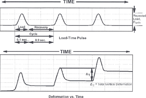
5.4.8 Permanent Deformation Characteristics
The permanent deformation characteristics of unbound materials are used in the empirical rutting distress models in the NCHRP 1-37A design methodology. This information is not required for rigid pavement design in the NCHRP 1-37A Design Guide or at all in the 1993 AASHTO design procedure. Permanent deformation characteristics are measured via triaxial repeated load tests conducted for many cycles of loading; Figure 5-30 shows schematically the typical behavior measured in this type of test. The repeated load permanent deformation tests are very similar to the cyclic triaxial tests used to measure resilient modulus (see 5.4.3), except that the cyclic deviator stress magnitude is kept constant throughout the test. There are at present no ASTM or AASHTO test specifications for repeated load permanent deformation testing. However, the first 1000 conditioning cycles of the AASHTO T307-99 resilient modulus testing procedure are often used for permanent deformation modeling.
The NCHRP 1-37A design methodology characterizes the permanent deformation behavior of unbound base, subbase, and subgrade materials using a model based on work by Tseng and Lytton (1989):
(5.27)| δa ( N ) = ξ1 | εo | e-(ρ/N)ξ2β εvh | ||
| εr |
in which
| δa | = | Permanent deformation for the layer/sublayer |
| N | = | Number of traffic repetitions |
| εo, β, ρ | = | Material properties |
| εr | = | Resilient strain imposed in laboratory test to obtain material properties εo, b, and r |
| εv | = | Average vertical resilient strain in the layer/sublayer as obtained from the primary response model |
| h | = | Thickness of the layer/sublayer |
| ξ1, ξ2 | = | Field calibration functions |
Tseng and Lytton provide regression equations for the εo/εr, ρ, and β terms. These regression equations were substantially revised during development of the NCHRP 1-37A design methodology. The revised equations implemented in the NCHRP 1-37A procedure are as follows:
(5.28)| log | εo | = 0.74168 + 0.08109 Wc - 0.000012157 MR | ||
| εr |
log β = -0.61119 - 0.017638 Wc
(5.30)log ρ = 0.622685 + 0.541524 Wc
In Eq. (5.28) through Eq. (5.30), MR is the resilient modulus in psi, and Wc is an estimate of the average in-situ gravimetric water content in percent. The NCHRP 1-37A procedure proposes the following equation for determining Wc in the absence of measured values:
(5.31)Wc = 51.712 ( CBR )-0.3586(GWT)0.1192 Wc ≤ Wsat
In Eq. (5.31), GWT is the depth to the groundwater table in feet, and CBR can be estimated from resilient modulus using:
(5.32)| CBR = | MR | (1/0.64) | ||
| 2555 |
The Wsat limit in Eq. (5.31) can be determined from
(5.33)| Wsat = | 2.75 | - 1 | * 100 / 2.75 | ||
| SPG |
where SPG is the saturated specific gravity of the soil. For laboratory test conditions, Wc is presumably equal to the tested water content.
Although fine-tuning of the calibration is still underway and therefore the expressions for ξ1, ξ2 may yet change, the current best estimates are as follows:
(5.34)ξ1 = 1.2 - 1.39 e-0.058(MR/1000) ≤ 1 × 10⁻⁷
(5.35)ξ2 = 0.7
In Eq. (5.34), a lower bound of 2.6 is set for MR/1000.
Figure 5-30. Accumulation of permanent deformations with repeated cyclic loading (LTPP, 2003).
5.4.9 Coefficient of Lateral Pressure
The coefficient of lateral earth pressure K0 is defined as the ratio of the horizontal to vertical in-situ effective stress:
(5.36)| K0 = | σho |
| σvo |
The coefficient of lateral earth pressure is an input in the NCHRP 1-37A design procedure. It is used to compute the combined in-situ and induced stress states within the pavement system.
Elasticity theory can be used to estimate K0 based on the confined Poisson expansion:
(5.37)| K0 = | ν |
| 1 - ν |
in which ν is Poisson's ratio. Values of K0 predicted by Eq. (5.37) for typical geomaterials range between 0.4 and 0.6.
A common empirical correlation for K0 for cohesionless and normally consolidated cohesive soils is the Jaky relationship:
(5.38)K0 = 1 - sin φ
in which φ is the friction angle. Overconsolidation in cohesive soils will increase the value for K0 above that given in Eq. (5.38). Figure 5-31 shows the typical relationship between K0, the overconsolidation ratio OCR, and the plasticity index PI.
Loading followed by unloading and reloading, such as occurs during compaction of unbound materials in pavements, often results in an increase in K0. The relative magnitudes of horizontal and vertical stress during a load-unload-reload path are shown schematically in Figure 5-32. Mayne and Kulhawy (1982) proposed the following model for K0 after loading-unloading-reloading:
(5.39)| K0 = ( 1 - sin φ ) | OCR | + | 3 | OCR | ||||
| OCRmax(1-sinφ) | 4 | OCRmax |
in which OCRmax is the maximum overconsolidation ratio achieved in the load path and the other terms are as defined previously.
Figure 5-31. Correlation between coefficient of lateral earth pressure and overconsolidation ratio for clays of various plasticity indices (Carter and Bentley, 1991).
Click here for text version of image
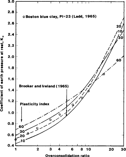
Figure 5-32. Horizontal and vertical in-situ stresses during a load-unload-reload path (Mayne and Kulhawy, 1982).

Notes
- See Appendix GG in Volume 2 of AASHTO (1986). Return to Text
- The 1998 supplement to the 1993 AASHTO Guide provides an alternate approach for determining the effective modulus of subgrade reaction for rigid pavements. Return to Text
- In the 1993 AASHTO Guide terminology, the subbase is defined as the granular layer between the PCC slab and the roadbed (subgrade) soil. This layer is termed the base layer in the 1998 supplement to the 1993 Guide. Return to Text
- For loads within 2000 pounds more or less of the 9000 pound desired value, deflections may be linearly scaled to equivalent 9000-pound deflections. Return to Text
| << Previous | Contents | Next >> |