

Aggregate Image Measurement System 2 (AIMS2): Final Report
EQUIPMENT
Technology
This project was launched on the basis of a prototype research system that was designed for investigating the possibility of using digital image analysis to characterize aggregate shape properties and to investigate the relationship of those characterizations to pavement and aggregate performance. This research system was called the Aggregate Image Measurement System (AIMS1). The system was not designed with manufacturability or convenience of use as primary objectives, and the initial platform proved to be costly to manufacture and cumbersome to operate. Therefore, a new system design was selected that met both the objectives of the project and melded industry requirements and expectations into the system. This system is referred to as AIMS2.
To best understand this project, a brief understanding of the technology is needed. The original research prototype platform, AIMS1, used a variable magnification microscope-camera system and two different lighting modes to capture aggregate images for analysis. The first lighting scheme creates a backlit image, which provides a particle silhouette. This image is converted to a binary tiff file analyzed for the shape characteristics of angularity and cross-sectional form. The second lighting scheme utilizes top lighting, which illuminates the top of each particle. A high-magnification, gray-scale image of the particle surface is captured and analyzed for a micro-texture characterization. The height of each particle is also captured from the position of the focal plane in this texture image, providing a three-dimensional form of each particle.
Original System
The research system utilized a large panel backlight and a microscope ring light for these different illuminations. The illumination hardware on the research system was costly, and uniform illumination was difficult to achieve . The multiple interconnections between system components made setup and troubleshooting of the equipment difficult. The AIMS1 system also had no provision to eliminate ambient laboratory lighting from influencing the results. The AIMS1 system is shown in figure 1.
The heart of the systems is the AIMS Software ©. Both coarse and fine aggregates are now characterized with the AIMS Software© algorithms. This software consists of a series of analysis algorithms that objectively quantify aggregate shape properties on both the macro scale (coarse and fine aggregate angularity, form, and flat and elongated ratio) as well as properties on a micro scale such as surface texture. For simplicity, the entire system will simply be referred to as the AIMS2.
Migration from the original AIMS1 research prototype platform to the newly designed AIMS2 production platform called retained the basic operating premise of variable magnification imaging combined with multiple illumination scenarios. However, it was desired to update the system components to less expensive and more robust hardware, to provide an enclosure to eliminate the ambient light concerns, and to simplify the overall equipment operation.
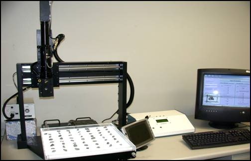
Figure 1. Photo. Original research Aggregate Imaging Measurement System equipment (AIMS1). (Photo courtesy of Pine Instrument).
The new system hardware represents an improvement over the research equipment. The redesign addressed the issues with ambient lighting effects, improved both the backlighting and the top lighting performance, tackled manufacturability issues, and streamlined the operator interface. The new system represents an improvement in overall performance in an integrated system.
Camera technology had progressed significantly after the AIMS1 system was developed. Camera image sensor technology had increased available resolutions while decreasing costs. An updated camera was selected to take advantage of these technology improvements. The higher resolution camera also provided an opportunity to eliminate one of two objective lenses used on the research unit while maintaining the image resolution required for the analysis. The second objective lens had a different focal length, which required a second physical microscope position. The camera-microscope unit was repositioned manually; therefore, eliminating this second objective lens simplified the design and operation of the equipment.
The AIMS1 unit used a microscope ring light in conjunction with external spot lights to achieve the desired top lighting. This configuration was difficult to precisely control. The large backlight panel also proved to be difficult to control for uniform lighting over the entire scan area. Efficient, precise, long-lasting LED technology was selected for both the top-lighting and backlighting requirements to address these shortcomings.
New System
The AIMS1 used an x-y-z gantry system to index the particles for imaging. This setup was expensive and difficult to align. A turntable configuration was selected for the AIMS2, powered by a stepper-motor gear-head combination to provide the sturdy platform needed for presenting the material to the imaging area. This configuration provides an added advantage by helping to reduce the size requirements of the backlight.
The AIMS2 turntable configuration utilizes a removable tray specific for each aggregate size to position the particles properly for imaging. The research system required the operator to place each coarse particle onto the table position accurately at specific grid points. The AIMS2 turntable trays simplify the material loading by requiring the operator to place the particles in a groove in the tray. Separation between particles is required, but the system also has routines to identify touching particles so that they are not included in the results. Fine particles are simply dispersed thinly over the tray groove in a manner similar to that used in the AIMS1 system.
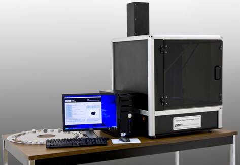
Figure 2. Photo: New Aggregate Imaging Measurement System equipment (AIMS2). (Photo courtesy of Pine Instrument).
In addition to making for easy cleanup, the removable tray design helps address another issue with the research equipment, associated with fine materials. The AIMS1 system was unable to capture images of translucent fine materials. Fine particles of light-colored materials often proved to be too translucent to provide adequate contrast and often were not captured with the original system's backlighting. The new system allows for trays of different colors to help provide contrast between the material particles and the background. The new system is supplied with a black opaque tray and a selectable feature that permits the material sample to be top-lighted for contrast in lieu of backlighting.
The dispersal of the fine material samples over the image field of view in a manner that produces no touching particles is impractical. Analyzing multiple particles as though they were one incorrectly influences the output values generating erroneous data. The research AIMS1 system utilized a Touching Particle Factor (TPF) algorithm to detect multiple fine particles that touched, appearing as one mass. This TPF algorithm worked reasonably well but was based on particle area and was thus sensitive to actual particle size, even within a single Superpave sieve size.
A new algorithm was devised for the AIMS2 system that reduced the sensitivity to particle size. This new method of detecting and removing touching particles from the analysis uses a geometric evaluation based on shape, called the convex hull perimeter. The convex hull perimeter is a track circumscribing the perimeter of the particle outline without any concave features. Areas around the perimeter that have a concave shape, like the valleys typically created when particles touch, are bridged. This convex hull perimeter is compared to the length of the actual silhouette perimeter including the concave valleys as a ratio called the convex hull perimeter ratio (CHPR). The CHPR value of 1.07 was determined to be effective at removing touching particles while still including angular particles in the data. This method is independent of actual particle size.
Details of the AIMS2 equipment and software are available online in the AIMS2 Operation Manual at http://www.pineinst.com/test/pdf/LMAFA2.pdf. The manual presents instructions for operation and maintenance and discusses the analyses and reports that the system generates.