

Asphalt Binder Cracking Device to reduce Low Temperature Asphalt Pavement Cracking
APPENDIX D. ABCD USER'S MANUAL
Detailed Procedure
- 1. Safety Precautions
- 1.1 Latex gloves helpful to keep binder off hands.
- 1.2 Insulated gloves necessary when holding heated asphalt container and pouring.
- 1.3 Safety glasses recommended when working with hot binder.
- 2. Power on Equipment
- 2.1 Turn on cooling chamber.
- 2.2 Turn on data collection hardware.
- 2.3 Computer
- 2.3.1 Plug USB cable from cooling chamber into computer.
- 2.3.2 Plug USB cable from data collection hardware into computer.
- 2.3.3 Power on the computer.
- 2.3.4 Wait long enough for all software to load and any Vista messages to disappear from the screen (a few minutes).
- 2.3.5 Double–click Excel 2007 icon on Desktop. This enables the data analysis add–in macro.
- 2.3.6 If pop–up messages appear anytime with the computer, clicking Cancel is usually appropriate.
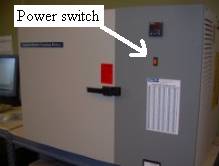
Step 2.1. Cooling chamber. Power switch up in "On" position.
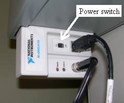
Step 2.2. Data collection hardware. Power switch pushed left in "On" position.
- 3. Prepare Spout
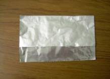
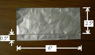
- 3.1 Cut a piece of aluminum foil approximately 6" x 6".
- 3.2 Fold the foil so that about 1" is not covered. Does not matter if the shiny or dull side is "up".
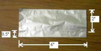
- 3.3 Rotate the foil 180o (do not flip over).
- 3.4 Fold the exposed 1" portion in half.
- 3.5 Fold along the joint you just created. Now you should have four thicknesses of foil for about 1/2" and two thicknesses of foil for about 2"
- 3.6 Fold a partial diagonal.
- 3.7 Fold another partial diagonal. Be sure all folds are creased.
- 3.8 You should have formed a 6–sided shape with approximate dimensions shown in the figure.
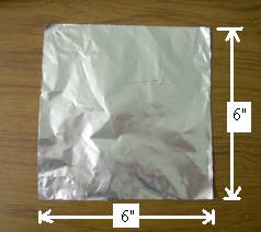
Step 3.1. Aluminum foil.
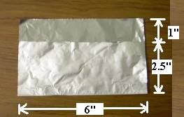
Step 3.2. First crease.
Step 3.3. Same image as Step 3.2 but foil rotated 180 degrees.
Step 3.4. The 1" portion has been folded in half.
Step 3.5. After the fold.
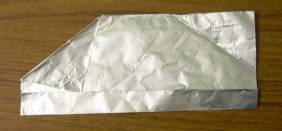
Step 3.6. After folding one diagonal.
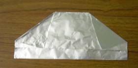
Step 3.7. After folding the second diagonal.
- 4. Mount Spout to Binder Sample Container
- 4.1 Line up foil on outside of container such that foil covers about 1" of height of the container. The thick portion of foil should line up just below the circumferential indent on the container.
- 4.2 Smooth the foil around the container indentation for a good seal.
- 4.3 Mold the foil over the lip of the container for the width of the foil, so binder cannot seep between container and spout.
- 4.4 Use index finger to form a curved spout. Spout should be bent so that it is horizontal.
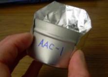
Steps 4.1 and 4.2. Line up foil on container.
Step 4.3. Mold foil onto container for good seal.
Step 4.4. Form curved spout.
- 5. Heating
- 5.1 Set the sample container with attached spout in the pouring ladle (optional) and place into oven.
- 5.2 Place stirring rod into oven.
- 5.3 Heat
- 5.3.1 One hour at 150°C for unaged binders.
- 5.3.2 One hour at 160°C for RTFO binders.
- 5.3.3 One hour at 170°C for PAV binders that have not been degassed. Then apply a 25 to 26.5" Hg vacuum (12.5 to 17.5 kPa absolute pressure) for 30 minutes.
- 6. Lubrication
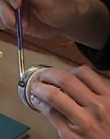
- 6.1 Lubricant should be glycerin/talc mixture in 1:1 mass ratio.
- 6.2 Lubricate four molds (or eight if you have an 8–ring system) using a brush.
- 6.2.1 Apply lubricant to inside portions of mold where the ring and binder will contact the mold.
- 6.2.2 Lubricate top of mold to aid cleaning after the test.
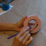
- 6.3 Lubricate four ABCD rings (or eight if you have an 8–ring system) using a brush.
- 6.3.1 Make sure that the ABCD ring is clear of debris.
- 6.3.2 Apply lubricant to the metal circumference portion.
- 6.3.3 Apply lubricant to the plastic top and bottom covers to ease removal of errant binder during trimming and after testing.
Step 6.2.1. Lubricate mold.
Step 6.3.2. Lubricate ring.