

Composite Bridge Decking, Final Project Report
3. DECK FABRICATION
This section describes the materials and methods used to fabricate deck panels. The fabrication method is flexible enough that various support spans can be accommodated with a slight modification of the panel structure; however, all variations are based on a standard pultrusion that serves as a building block for the deck.
Materials
Resin
The resin used is a fire-resistant vinyl ester resin from Ashland Chemical called Derakane 510C.
Fiber
See tables 2 and 3 for detailed descriptions of the fiber layers. The reinforcement is E-glass rovings, woven mat, and chopped strand mat (CSM) from PPG and Owens-Corning. Glass from other manufacturers could be used as well. The individual ply details of the laminate constructions for the horizontal and vertical walls also are given in the tables.
| Material | Angle (°) | Areal Weight (oz/yd2) | Thickness (in.) |
|---|---|---|---|
| 1 ½ oz CSM | n/a | 1.5 | 0.016 |
| E-TTXM 2308 | 45 | 6.27 | 0.032 |
| 90 | 11.52 | ||
| -45 | 6.27 | ||
| CSM | 8.10 | ||
| Roving - 3.7 ends/in. | 0 | 38.3 | 0.038 |
| E-TTXM 2308 | 45 | 6.27 | 0.032 |
| 90 | 11.52 | ||
| -45 | 6.27 | ||
| CSM | 8.10 | ||
| Roving - 3.7 ends/in. | 0 | 38.3 | 0.038 |
| E-TTXM 2308 | 45 | 6.27 | 0.032 |
| 90 | 11.52 | ||
| -45 | 6.27 | ||
| CSM | 8.10 | ||
| 1 ½ oz CSM | n/a | 1.5 | 0.016 |
| TOTALS | 0 | 76.6 | 0.204 |
| 90 | 34.6 | ||
| +45/-45 | 37.6 | ||
| CSM | 27.3 |
| Material | Angle (°) | Areal Weight (oz/yd2) | Thickness (in.) |
|---|---|---|---|
| 1 ½ oz CSM | n/a | 1.5 | 0.017 |
| E-TTXM 2308 | 45 | 6.27 | 0.032 |
| 90 | 11.52 | ||
| -45 | 6.27 | ||
| CSM | 8.10 | ||
| E-TTXM 2308 | 45 | 6.27 | 0.032 |
| 90 | 11.52 | ||
| -45 | 6.27 | ||
| CSM | 8.10 | ||
| Roving – 7.6 ends/in. | 0 | 78.6 | 0.078 |
| E-TTXM 2308 | 45 | 6.27 | 0.032 |
| 90 | 11.52 | ||
| -45 | 6.27 | ||
| CSM | 8.10 | ||
| E-TTXM 2308 | 45 | 6.27 | 0.032 |
| 90 | 11.52 | ||
| -45 | 6.27 | ||
| CSM | 8.10 | ||
| 1 ½ oz CSM | n/a | 1.5 | 0.017 |
| TOTALS | 0 | 78.6 | 0.240 |
| 90 | 46.1 | ||
| +45/-45 | 50.2 | ||
| CSM | 27.3 |
Composite Materials
Table 4 provides details of the material properties of the composite material.
| Laminate Unit Value | Unit | Values for Horizontal Walls Thickness = 0.20 in. |
Values for Inclined Walls Thickness = 0.24 in. |
|---|---|---|---|
| Elastic modulus of 0 degree, Ex | psi | 3.39 E+6 | 3.18 E+6 |
| Elastic modulus of 90 degree, Ey | psi | 2.33 E+6 | 2.39 E+6 |
| Shear modulus, Gxy | psi | 0.74 E+6 | 0.75 E+6 |
| Ultimate tensile strength of 0 degree | psi | 63,600 | 55,600 |
| Ultimate tensile strength of 90 degree | psi | 20,600 | 22,300 |
| Ultimate compressive strength of 0 degree | psi | 54,800 | 51,600 |
| Ultimate compressive strength of 90 degree | psi | 22,300 | 23,600 |
| Ultimate shear strength | psi | 8,000 | 8,600 |
| Poisson’s ratio | - | 0.27 | 0.27 |
Grout
The grout selected was epoxy based. This is used to add compressive strength to tube sections and is used for field joints. Properties are shown in table 5.
| Properties | Unit | Value |
|---|---|---|
| Compressive strength | psi | 1.32E+4 |
| Tensile strength | psi | 2.35E+3 |
| Elastic modulus | psi | 2.16E+6 |
Tubes
A basic building block of the deck is the trapezoid-shaped pultrusion. It is a three-cavity trapezoid, as shown in figure 1. Figure 2 shows the standard dimensions, and figure 3 provides details regarding the fiber architecture.
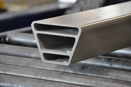
Figure1. Photo. Pultruded tube.
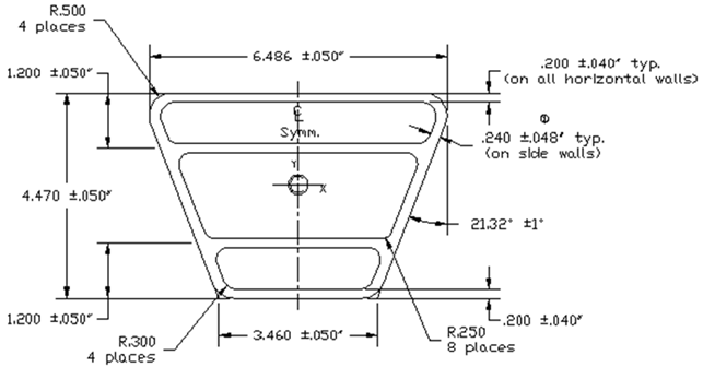
Figure 2. Diagram. Dimensions of tube cross-section.
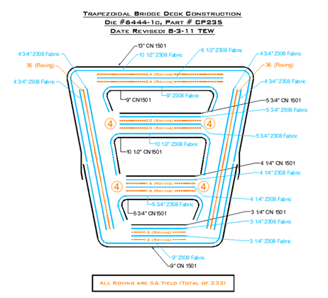
Figure 3. Diagram. Fiber architecture of the tube.
Panel Fabrication Methods
Figures 4 through 11 illustrate the steps for assembling the deck panels.
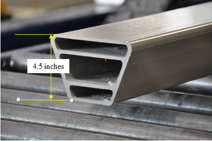
Figure 4. Photo. Pultruded tube subcomponent consisting of E-glass and vinyl ester resin.
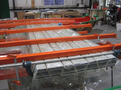
Figure 5. Photo. Tube subcomponents are bonded together with adhesive to form a panel.
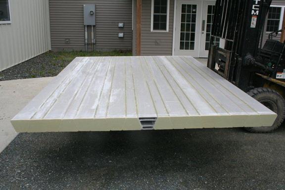
Figure 6. Photo. Panel ends are capped and radii between tubes filled with thixotropic resin.
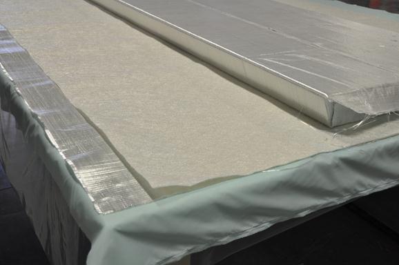
Figure 7. Photo. The panel is wrapped in glass fiber in preparation for infusion with vinyl ester resin.
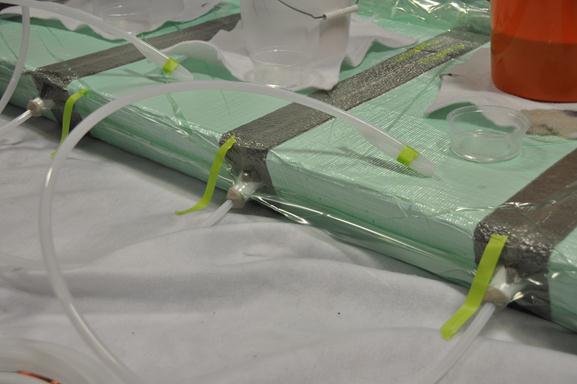
Figure 8. Photo. Infusion of resin for outer wrap using vacuum-assisted resin transfer molding (VARTM) method.
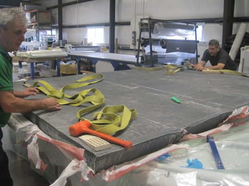
Figure 9. Photo. Infused deck panel is stripped and inspected for thorough wet-out.
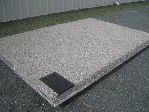
Figure 10. Photo. Adhesive and stone applied for course 1 of the wearing surface. Note the black prefabricated railing post pad and stone bonded to the sloped surface.
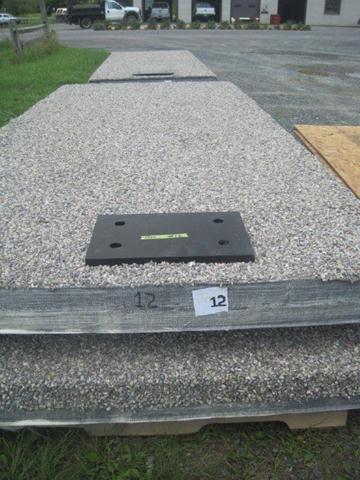
Figure 11. Photo. Panels labeled for shipping to the job site.