

Precast Bent System for High Seismic Regions: Laboratory Tests of Column-to-Footing Socket Connections
CHAPTER 7. SUMMARY AND CONCLUSIONS
Summary
System Concept
A new column-to-footing "socket" connection suitable for use with spread footings was developed and tested at the University of Washington. The connection concept is intended to accelerate the construction of bridge piers and to provide excellent seismic performance.
First, a column is precast with the intentional surface roughening around the base. Then the column is set in the excavation, plumbed, leveled, and braced. Finally, the footing reinforcement is tied around the column, and the foundation is cast.
The column longitudinal bars are straight and are terminated with mechanical anchors instead of being bent outwards into the footing. This configuration has several advantages. It avoids fit-up of bars in ducts at the base of the column, the column detailing can be almost identical to that of a cast-in-place column, and no grouting is needed. Other advantages include better seismic performance, because the force transfer between the column and the footing is more direct, as suggested with strut-and-tie modeling. This use of headed bars also makes fabrication, transportation, and erection safer, easier, and quicker.
Design of Test Specimens
WSDOT selected a prototype bridge to demonstrate the implementation of the proposed rapid construction technology. The laboratory specimens represented the essential details of the bridge footings at 42 percent scale. The tests provided proof of concept for the seismic performance of the system, and the bridge construction was used for field verification of the system's constructability.
Three cantilever-footing specimens were constructed. Specimens SF-1 and SF-2, illustrated in figure 95, were designed and tested before starting the construction of the prototype bridge. Specimen SF-1 was designed to satisfy the conventional cast-in-place requirements of the AASHTO Seismic Guide Specifications, with minor modifications. Slots in each direction were created at the base of the precast column to allow some of the bottom footing reinforcement to pass through the slots.
Specimen SF-2 was similar to SF-1 but simpler and more economical to construct. It did not have slots at the base of the column, and it contained less reinforcement, so it was inherently less conservative. Some classes of reinforcement (such as footing ties) were reduced below the level specified in the Caltrans SDC to determine whether they were needed. In both specimens, the column was segmental and spliced at the top of the anticipated plastic hinge. The segments were included to test the seismic performance of such a splice, because splices were included in the prototype to investigate their constructability.
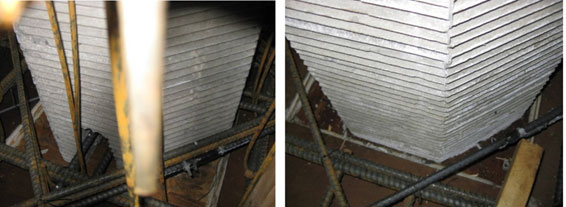
Figure 95. Photos. Specimen SF-1 (left) and specimen SF-2 (right).
Specimens SF-1 and SF-2 failed in column flexure and so revealed little about the strength of the footing connection. To investigate the connection behavior, specimen SF-3 was designed to fail in the connection region. This goal was achieved by reducing the footing depth and adding steel to suppress unwanted modes of failure, such as footing flexure and one-way shear.
Experimental Testing
Each specimen was subjected to the following series of tests:
- First, each specimen was subjected to an axial load of at least 240 kips, which is the largest factored load expected to act on the connection after reduction to laboratory scale. Specimen SF-3 was loaded to an even higher axial load (342 kips).
- Second, the vertical load was reduced to 159 kips, which represented the service dead load plus vertical (overturning) load resulting from horizontal earthquake motion, and cyclic horizontal loading was applied to the column using a displacement controlled actuator.
- Third, after the cyclic loading was complete, specimens SF-1 and SF-2 were subjected to a pure axial-load test to failure to investigate the resistance of the footing to push-through of the column. Such loading was not possible in specimen SF-3, because the footing had already failed in punching shear.
In specimens SF-1 and SF-2, which had the thicker footings, the damage due to lateral loading was concentrated at the base of the columns, and the connections were nearly undamaged. Column flexural failure was initiated by buckling of the longitudinal bars (at drift ratios of about 7 percent) and was completed by fracture of those bars as they straightened during the subsequent tension part of the loading cycle. This behavior has been observed in many cast-in-place columns tested at the University of Washington and elsewhere. The failure of these specimens under pure axial load, in the third phase of testing, was due to crushing of the concrete within the hinging region. When that load was applied, the spiral had already failed during the lateral load tests.
Specimen SF-3, which had a much thinner footing, experienced much more damage in connection region. Nonetheless, the specimen carried the axial load to a drift ratio of 10 percent before the precast column punched through the supporting footing in a failure mode caused by combined punching shear and moment transfer.
Experimental Analysis
The measured responses of the test specimens were compared with the results of analytical models for both the spread footing and column. Table 24 summarizes the ratios of the demands on the footings to the nominal calculated capacities using the measured material properties.
Table 24. Summary of ratios of footing demands to calculated capacities.
| Design Criteria | SF-1 | SF-2 | SF-3 |
|---|---|---|---|
| Footing cracking, Mu /Mcr | 0.91 | 0.89 | 3.97 |
| Footing flexural strength, Mu/Mn | 0.57 | 0.57 | 0.75 |
| Footing one-way shear strength, Vu/Vn | 0.43 | 0.56 | 0.75 |
| Connection combined punching shear and moment transfer under cyclic loading, vu/vn |
0.20 | 0.25 | 1.27 |
| Punching shear strength under pure axial load, Vu/Vn | 1.19 | 1.35 | 1.82 |
| Shear-friction push-through strength under pure axial load, Vu/ Vn |
1.44 | 1.90 | 0.74 |
| Joint shear (compressive), |
0.23 | 0.21 | 0.32 |
| Joint shear (tensile), |
0.24 | 0.22 | 0.44 |
The flexural demands in the footings were approximately 10 percent below the calculated cracking capacities for the two thick footings (SF-1 and SF-2), but the demands greatly exceeded the nominal cracking moment for the thin footing (SF-3). These findings are consistent with the observed damage patterns.
The footing and connection demands for specimens SF-1 and SF-2 were well below the calculated capacities for footing flexural strength, footing one-way shear, combined punching shear and moment transfer, and joint shear. These calculations are also consistent with the observed damage patterns. The demands exceeded the calculated capacities for punching shear under pure axial load and for shear friction. Neither specimen SF-1 nor specimen SF-2 failed in these manners.
The demands on the thin footing in SF-3 were lower than the nominal capacities for footing one-way shear, shear friction, and joint shear. The specimen did not fail in any of these modes. The demands were greater than the capacities for both punching shear pure axial load and for combined punching shear and moment transfer. Specimen SF-3 successfully withstood the pure axial load and demonstrated that the capacity of the thinner spread footing was sufficient. The load exceeded 140 percent of the maximum axial load expected on the connection. Specimen SF-3 failed in the combined punching shear and moment transfer. The demand exceeded the nominal capacity by 27 percent.
Conclusions
Connection concept. The column-to-footing socket connection can be designed to behave at least as well as a comparable cast-in-place column-to-footing connection.
Behavior of precast columns. In all three specimens, the response to cyclic lateral loading of the precast columns was essentially identical to that of a cast-in-place column with the same geometry and reinforcement. Such precast columns can be designed following the same design approach used to design cast-in-place columns, including the calculation of displacement capacity.
Need for mechanical anchors. In specimens SF-1 and SF-2, the bar stress directly behind the anchors reached values of up to about 3 ksi. The headed anchors were more active in SF-3. These measurements showed that the anchors were providing partial anchorage and should be included in future implementations of the socket connection.
Design against overturning . The procedures outlined in the AASHTO Seismic Guide Specifications for determining the expected strength of the column and the size of footing required to prevent overturning proved to be slightly conservative in all three tests.
Design against footing failure. The procedures outlined in the AASHTO Seismic Guide Specifications for determining the required flexural strength of the footing were effective in preventing footing failure in all three column tests. In specimens SF-1 and SF-2, with hfooting = 1.1Dcol, the amount of flexural reinforcement in the footing was controlled by minimum requirements, so the absence of footing failure was expected. In those specimens the footing did not even crack in flexure, and nearly all the moment was carried by the concrete.
In specimen SF-3, with hfooting = 0.5 Dcol, the footing reinforcement was controlled by strength requirements. The footing cracked, but the stress in the footing steel never rose above 26 ksi. Failure was controlled by shear stress in the connection caused by loading in combined shear and moment transfer. For thinner footings, it is advisable to include a check for a potential failure in a combined punching shear and moment transfer, using the procedure outlined in ACI 318-08. The AASHTO LRFD Design Specifications contain no provisions for this potential failure mode, despite the fact that it proved critical here.
Vertical ties in the footing. When the column steel consists of straight bars equipped with headed anchors, rather than the conventional bent-out bars, the prescriptive vertical footing ties specified by the AASHTO Seismic Guide Specifications perform no useful function and can be omitted. This conclusion applies only to the prescriptive ties, and not to ties that are needed to supply shear resistance required to resist computed shear demands.
Shear-friction push-through resistance of connection. The shear friction strength of the connection between column and footing was sufficient to prevent any slip, much less sliding failure, in any of the three test specimens. In specimens SF-1 and SF-2, in which the footing was essentially undamaged, the connection interface withstood a shear stress of 611 psi with no sign of damage even after the specimens had been subjected to large lateral deformations.
Shear-friction reinforcement. The bottom diagonal bars included in the thick footing test specimens (SF-1 and SF-2) experienced little stress during the factored axial-load test and during the cyclic lateral-load tests and, therefore, proved unnecessary for resisting shear friction. During these tests, the footing remained essentially elastic. If the column is circular or octagonal and the opening in the main footing reinforcement is square, it is recommended that at least one set of diagonal bars be included in the top and bottom mat to avoid the existence of unreinforced concrete in the corners.
Joint shear stress. Analysis showed that the permissible tensile and compressive stresses due to joint shear were not exceeded in any of the specimens, and that is in agreement with the observed lack of cracking. The largest joint shear demands were in specimen SF-3.
Column splice location. Any splice in the column should be located outside the plastic hinge length, as defined by the AASHTO Seismic Guide Specifications. The splices inspecimens SF-1 and SF-2 were located exactly where yielding would be first expected when the column moment at the base reached its full plastic value ( Mpo), but they were closer to the base than the prescriptive 1.5Dcol value included in the AASHTO Seismic Guide Specifications criteria for plastic hinge length. The longitudinal reinforcement just yielded there, but the joints did not suffer damage or display any residual crack opening.
Column splice design. The splice length in specimens SF-1 and SF-2 was controlled by the length required to splice the confined column bars outside the ducts. The development length used in design should take into account any top bar effects that arise from casting in a particular direction (i.e., horizontally or vertically).
Column shear resistance at the splice. No shear slip or damage occurred at the splice in either of the two specimens that included a splice (SF-1 and SF-2). Each splice was made with a circular key at the column center. The average shear stress on the gross column section reached a maximum of 156 psi.
Recommendations
The proposed system is ready for implementation in the field in cases where the configuration and geometry are similar to those used in the tests. The tests showed excellent seismic performance, and the construction of the prototype demonstrated the system's constructability.
These three tests begin to form the data set needed for design. More data on the behavior of socket connections are still needed to allow design in wider range of configurations. The wooden strips used here provided sufficient roughness for the column surface, but less labor intensive methods of creating the roughened surface should be investigated as well.
Finite element analysis of the connection should be conducted to investigate numerically the distribution of stress in the connection region and to allow extrapolation of these test results to other situations.