Transportation Research Board 93rd Annual Meeting
PDF files can be viewed with the Acrobat® Reader®
GEORGE WASHINGTON MEMORIAL PARKWAY ARLINGTON MEMORIAL BRIDGE
1
Description of Existing Bridge
- This bridge was built in 1932
- Historic structure
- As-built plans exist – Several Construction Contracts

Bridge deck and sidewalk
2
Description of Existing Bridge (cont.)
- Movable Steel Truss Bascule Span
- Total length of the bridge: 2,108 feet
- Bascule span:
- 216 feet (Main Trunnion to Main Trunnion)
- Approach Spans:
- 10 Total (5 on each side of bascule)
- Curb to curb: 60 feet (6 lanes)
- Sidewalk width 17 feet
|
- Estimated water depth varies (10 feet to 30 feet)
- Known Utilities (Survey Completed):
- Pepco
- FAA
- Tunnel for submarine cable
|

3
Existing Deck and Sidewalks
 of the Arlington Memorial Bridge. The slide in the upper left shows the bumpy surface of the roadway (bridge deck), including ruts, spalls and asphalt patches. Bulges in the pavement are also visible from repeated repair/patching with asphalt. The image in the upper right shows a hole in the road way surface (bridge deck) where the entire asphalt overlay is missing and the concrete bridge deck below it is showing. Also visible is a dark area of asphalt where the roadway had been previously repaired/patched. The image in the lower left shows the sidewalk of the bridge; the sidewalk has large areas of deterioration and cracking It also shows where the deterioration in the sidewalk had been patched with asphalt but the patch also has deteriorated. The image in the lower right shows a pothole in the roadway surface (bridge deck). The asphalt roadway surface also has ruts and there are areas on the road surface that have been previously repaired/patched. The slide number is visible in the lower right corner.")
Deterioration of roadway surface |
 of the Arlington Memorial Bridge. The slide in the upper left shows the bumpy surface of the roadway (bridge deck), including ruts, spalls and asphalt patches. Bulges in the pavement are also visible from repeated repair/patching with asphalt. The image in the upper right shows a hole in the road way surface (bridge deck) where the entire asphalt overlay is missing and the concrete bridge deck below it is showing. Also visible is a dark area of asphalt where the roadway had been previously repaired/patched. The image in the lower left shows the sidewalk of the bridge; the sidewalk has large areas of deterioration and cracking It also shows where the deterioration in the sidewalk had been patched with asphalt but the patch also has deteriorated. The image in the lower right shows a pothole in the roadway surface (bridge deck). The asphalt roadway surface also has ruts and there are areas on the road surface that have been previously repaired/patched. The slide number is visible in the lower right corner.")
Deterioration of the sidewalks |
 of the Arlington Memorial Bridge. The slide in the upper left shows the bumpy surface of the roadway (bridge deck), including ruts, spalls and asphalt patches. Bulges in the pavement are also visible from repeated repair/patching with asphalt. The image in the upper right shows a hole in the road way surface (bridge deck) where the entire asphalt overlay is missing and the concrete bridge deck below it is showing. Also visible is a dark area of asphalt where the roadway had been previously repaired/patched. The image in the lower left shows the sidewalk of the bridge; the sidewalk has large areas of deterioration and cracking It also shows where the deterioration in the sidewalk had been patched with asphalt but the patch also has deteriorated. The image in the lower right shows a pothole in the roadway surface (bridge deck). The asphalt roadway surface also has ruts and there are areas on the road surface that have been previously repaired/patched. The slide number is visible in the lower right corner.")
Deterioration of the roadway surface |
4
Existing Deck - Underside

Photo taken on 07/21/2010 |

Photo taken on 02/08/2012 |
5
Deck - Recent Repairs

Photo taken on 09/29/2012
6
Deck - Recent Repairs

Photo taken on 10/01/2012
7
Deck - Recent Repairs

Photo taken on 09/29/2012
8
Sidewalk - Recent Repairs
. There is also a hole all the way through the sidewalk adjacent to a metal joint that connects portions of the sidewalk. The slide number is visible in the lower right corner.")
Photo taken on 09/20/2012
9
Eagle’s Eye View
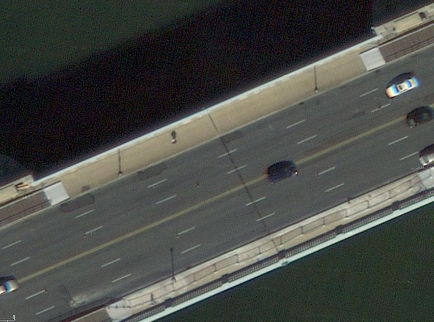
10
Eagle’s Eye View

11
Deck Study – Core Boring Locations
 taken from the deck of the span between Pier 6 and Pier 5; core #5 is located 69 feet from the expansion joint at Pier 5, and 10-ft-3-in south of the traffic-side of the north sidewalk. Four cores have been taken from the concrete deck of the approach span between Pier 5 and Pier 4. The first core in that span is core #12 and is located 68 feet-6-inches from the expansion joint at Pier 5 and 6-ft-5-inches north of the centerline of the bridge deck. The second core in that span is core #6 and is located in the south sidewalk, 17-ft-2-inches from the expansion joint at Pier 5 and 5-ft-3-in south of the traffic-side of the south sidewalk. The third core in that span is core #10, and is located 62-ft-5-inches from the expansion joint at Pier 4 and 3-ft-10-inches north of the centerline of the bridge deck. The fourth core in that span is core #11, and is located 53 feet from the expansion joint at Pier 4 and 4-ft-10-inches south of the traffic-side of the north sidewalk. One concrete core, core #4, was taken from the deck of the span between Pier 4 and Abutment 3; it is located 6-ft-3-in from the expansion joint at Pier 4 and 2-ft-9-inches south of the traffic-side of the north sidewalk.
The second image is below the first image; it is an elevation view of the bridge (view from the side of the bridge), displaying five spans from the Virginia end of the bridge and half of the bascule span. The location of the east face of Abutment 4 is at Station 26+18. The distance from the east face of Abutment 4 on the Virginia end of the bridge to the centerline of the bascule span is 929 feet. Pier 6 is 32-ft wide. Pier 5 is 33-ft wide. Pier 4 is 35-ft wide and Abutment 3 nearest the bascule span is 41-ft wide. The span length of the approach span closest to the Virginia end of the bridge between Abutment 4 and Pier 6 is 66 feet. The span length of the approach span between Pier 6 and Pier 5 is 72-feet-8 inches. The span length of the approach span between Pier 5 and Pier 4 is 177-feet-4 inches. The span length of the approach span closest to the bascule span between Pier 4 and Abutment 3 is 180 feet. The distance from Abutment 3 to the centerline of the bascule span is 92 feet.
The third image is below the second image and it depicts a plane view of the bridge, which is the view one would see from the sky looking down at the bridge. This third image only shows the five spans from the Washington, DC end of the bridge, and half of the bascule span to the centerline of the bascule span. Three cores have been taken from the deck of the span between Pier 3 and Pier 2. The first core in that span is core number 3 and is from the north sidewalk; it is located 17 feet from the expansion joint at Pier 3 and 2-feet-6-inches from the water-side of the sidewalk. The second core in that span is core number 2, and is located 17-feet from the expansion joint at Pier 3 and 3 to 6-inches from the traffic-side of the north sidewalk. The third core in that span is core number 9. It is located 23-feet-8-icnhes from the expansion joint at Pier 2 and 4-feet-1-inch north of the centerline of the bridge deck. There is one core, core number 1, taken from the deck of the span between Pier 2 and Pier 1. It is located 59-feet from the expansion joint at Pier 1 and 3-feet-6-inches south of the traffic-side of the north sidewalk. There is one core, core number 7, taken from the south sidewalk of the span between Pier 1 and Abutment 1. It is located 69-feet-8-inches from west face of Abutment 1 and 12-feet-2-inches north of the water-side of the south sidewalk. The last core is core #8, and it is from the deck of the approach span at the Washington, DC end of the bridge. The core is located 31-feet-8-inches from the west face of Abutment 1 and 4-feet-7-inches north of the centerline of the bridge deck.
The fourth image is below the third image; it is an elevation view of the bridge (view from the side of the bridge), displaying five spans from the Washington, DC end of the bridge and half of the bascule span. The distance from the west face of Abutment 1 on the Washington, DC end of the bridge to the centerline of the bascule span is 929 feet. Abutment 2 is at the east end of the bascule span and is 41-feet wide. Pier 3 is 35-feet wide. Pier 2 is 33-feet wide, and Pier 1 is 32-feet wide. The span length of the approach span between Abutment 2 and Pier 3 is 180 feet. The span length of the approach span between Pier 3 and Pier 2 is 177-feet-4-inches. The span length of the approach span between Pier 2 and Pier 1 is 172-feet-8-inches. The span length of the approach span between Pier 1 and Abutment 1 is 166 feet. The location of the west face of Abutment 1 is at Station 7+60.")
12
Deck Study – Retrieved Core Findings
 and efflorescence. The second image is of core number 2, is located just to the right of the first image, and shows asphalt and concrete rubble. The third image is of core number 3, is located to the right of the second image, and shows a small intact piece of concrete with some spalling and efflorescence at one end of the core. The fourth image is of core number 4, is located to the right of the third image, and shows small pieces of asphalt and concrete rubble and pieces of a membrane. The fifth image is of core number 5, is located to the right of the fourth image, and shows pieces of asphalt with asphalt, membrane, and concrete rubble. The sixth image is of core number 6, is located below the first image, and shows four small pieces of concrete and three very small pieces of concrete; this is evidence of horizontal cracking (delaminations), vertical cracking, and efflorescence. The seventh image is of core number 7, is located below the second image, and shows two separate pieces of concrete, evidence of a vertical crack. The eighth image is of core #8, is located below the third image, and shows one intact piece of asphalt two inches long and many pieces of concrete rubble. The ninth image is of core number 9, is located below the fourth image, and shows a 2-inch piece of asphalt with membrane and three-and-a-half inch concrete core with a horizontal crack at the bottom of it and concrete rubble. The tenth image is of core number 10, is located below the fifth image, and shows asphalt, membrane, and concrete rubble. The eleventh image is of core number 11, is located below the sixth image, and shows a fully intact core made up of two inches of asphalt and three-and-a-half inches of concrete. The twelfth image is of core number 12, is located below the seventh image, and shows a two inch piece of asphalt with membrane with concrete rubble below it.")
13
Eastern Federal Lands Highway Division & Turner-Fairbanks Highway Research Center working together!
RABIT – Data Based Assessment Tool
 |
- Panoramic Camera collects high-quality 360-degree images around the bridge deck.
- High-Definition Imaging collect high-quality images of the bridge deck.
- Electrical Resistivity Probes characterizes the corrosive environment of concrete deck.
- Impact Echo and Ultrasonic Surface Waves determine concrete delamination and concrete deck strength.
- Ground Penetrating Radar (GPR) records and marks location data.
- Global Positioning System (GPS) uses electromagnetic waves to map rebars and assess concrete deterioration.
|
14


