| FHWA > HPMS Field Manual > Appendix N: Procedures for Estimating Highway Capacity |
|
An update of the manual is available! - HPMS Field Manual
HPMS Field ManualAppendix N: Procedures for Estimating Highway CapacityTable of Contents
Procedures for Estimating Highway CapacityHPMS SoftwareThe procedures used in the HPMS software for determining highway capacity conform to the Highway Capacity Manual 2000 (HCM 2000). The capacity calculations are based on service flow rates for level of service E and are for the peak direction. The capacity coded in HPMS is used for system planning analysis, not project level analysis. The number of peak lanes (number of through lanes used in the peak period in the peak direction) coded in HPMS (Item 87) is used in the procedures for determining capacity. The number of through lanes coded in HPMS (Item 34) is used in the procedures to determine the number of lanes on the facility. The equations for determining the volume/service flow ratio (V/SF) are shown at the end of this Appendix along with tables that contain the data items used in the capacity calculations and in the V/SF ratio. All references to chapters, tables, etc., are to the HCM. All calculations and values in the Appendix are in English units; i.e., miles per hour (mph), feet, miles, etc. The assumptions made by FHWA for adjustment factors used in the procedures are consistent with the recommended values in the HCM. The reference to the data item value in the procedures indicates the way the data item is coded in the HPMS. Hierarchy Of Application For Capacity ProceduresFigure 1 presents the decision rules for applying the methodologies of measuring capacity for highway sections. The logic is based on first identifying if the section is on a structure or is a rural unpaved road; and second if it is characterized by "interrupted flow;" that is, a section where traffic is influenced by traffic control devices (signals and stop signs). If the traffic control device density is below the thresholds (0.5 signals or stop signs per mile), the facility is assumed to be an uninterrupted flow facility. For these, the following definitions apply. Freeways (Urban and Rural) For HPMS, the design characteristics, not the functional classification, determine if a section is a freeway ("freeway by design"). The characteristics of a freeway are:
Multilane Highways (Urban and Rural) The main characteristic distinguishing these facilities from freeways is the lack of access control. They are defined by:
Rural Two-Lane Highways All rural sections that have two through lanes of travel and two-way operation are covered by this method. Most of these sections will not have full access control, though this condition does exist in the HPMS data. Rural One-Lane, One-Way Highways This is a rare condition in HPMS, but it does exist. Rural Three-Lane Highways These are highways with two through lanes in one direction and one through lane in the opposite direction. Urban One/Two/Three-Lane Highways These are highway sections in urban areas that do not meet the traffic control device density requirement for either signals or stop signs. They can either have one-way or two-way traffic flow, as follows:
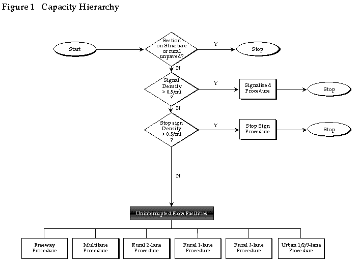 Figure 1. Capacity Hierarchy
|
||||||||
|
Updated: 10/12/2022 |