

Reactive Solutions - An FHWA Technical Update on Alkali-Silica Reactivity
Volume 3, Issue 1 Winter 2010
Inside this Issue:
- The Damage Rating Index: A Useful Took for Determining Damage Caused by ASR in Concrete
- Editor's Corner
- Ask The Experts
- Prestressed Precast Concrete Pavement (PPCP) System Use in Delaware
- Schedule of Events
The Damage Rating Index: A Useful Took for Determining Damage Caused by ASR in Concrete
The Damage Rating Index (DRI) is a petrographic method that was developed by Grattan-Bellew and Dunbar in 1992 and 1995 to evaluate the extent of damage in concrete caused primarily by alkali-silica reactivity (ASR). The test is not intended to replace the petrographic examination of hardened concrete but is proposed as a tool to further quantify the extent of damage in concrete affected by ASR and/or other harmful mechanisms. The DRI can be applied to concrete extracted from field structures or used to perform the diagnostic evaluation in order to determine the cause of deterioration in concrete specimens undergoing laboratory testing. The DRI is used as part of the petrographic evaluation under the Federal Highway Administration's (FHWA) ASR Development and Deployment Program as an additional tool to determine the presence and extent of ASR in structures under evaluation. This test has also proved useful at airports and for other transportation and water retaining structures to help determine which sections or structural elements actually suffered from ASR rather than other similar looking distress mechanisms.
How does it work?A concrete sample, either extracted from a structure or collected after completion of laboratory testing, is prepared for petrographic evaluation. The concrete specimen is generally cut axially in two, providing maximum surface area. The surface is then polished and segmented by a grid of squares that are 0.4 in. x 0.4 in. (1 cm x 1 cm) in size (see Figure 1).
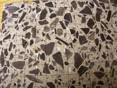
Figure 1. Prepared concrete sample for DRI evaluation.
The sample is then observed using a stereomicroscope at 16-times magnification. Although there are no strict rules regarding the number of squares to examine, it is generally recognized that a minimum of 200 squares forms a valid test. This number may actually be significantly larger in the case of mass concrete containing larger aggregate particles.
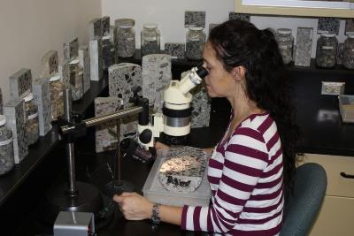
Figure 2. Polished sample being evaluated for its DRI.
The presence of each of the petrographic features listed in Table 1 is counted in each of the squares examined and those counts are multiplied by “weighting factors”. These “weighting factors” represent the relative importance of each of the listed features in the deterioration process caused by ASR. The DRI represents the normalized value [to 16 in² (100 cm2)] of the presence of these features once their counts have been weighted and multiplied.
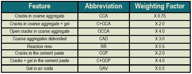
Table 1. Petrographic features and their corresponding weighting factor.
What does it tell us?
Although there is no arbitrary value which will indicate whether the concrete suffers deterioration due to ASR, nor its severity, DRI values above 50 are generally suggestive of significant damage due to ASR. Figure 3 illustrates the results of a DRI evaluation.
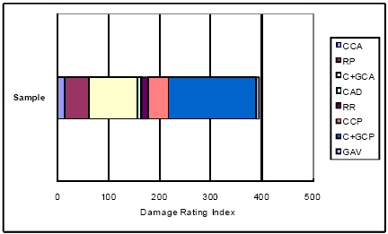
Figure 3. Example of results from a DRI evaluation. The corresponding value for this sample is 395, which would be indicative of considerable deterioration due to ASR. [Refer to Table 1 for abbreviations.]
Limitations of the Test
Although the test can provide very useful information on the type and extent of deterioration in the concrete under evaluation, DRI values can vary significantly as a function of the experience of the operator/petrographer. Recent work performed at Laval University has shown that the operator variability of the test can be reduced significantly by providing proper training in the method. A picture album containing specific instructions has been prepared to help reduce the "interpretative" aspect of the test that can result in significant variations. The album is currently being finalized in French and an English translation is expected in the coming months.
Conclusion
It is generally recommended that concrete samples be sent to a petrographer in order to confirm the presence of ASR in a concrete structure, in addition to laboratory testing, such as stiffness damage testing and direct tensile strength. Using the DRI as a companion evaluation alongside petrography assists greatly in confirming, or ruling out, if the damage to a questionable structure is primarily an effect of ASR. In addition to these benefits, the DRI is even more valuable for determining the extent of damage between various elements or sections of the structure under evaluation.
Editor's Corner
Dear Readers,
This season's issue of the Reactive Times includes articles on a technique for determining a damage rating index for ASR-damaged concrete using petrographic analysis and a novel system for repairing ASR-damaged concrete pavement using prestressed precast concrete panels.
In other developments, the dates have been set for the 14th International Conference on Alkali-Aggregate Reactions (ICAAR), so mark your calendar!. The meeting will be held in Austin, TX from May 20-25, 2012. This will be the first time that the United States has hosted this AAR conference since 1978. Another recent announcement is the formation of the International Centre of Research and Applied Technology for Alkali Aggregate Reactions (AAR), which has been established at the laboratory of Mannvit Engineering, in Iceland. The center includes experts from around the world including North America. For more details check the link at http://www.mannvit.com/TestingResearchLab/CentreofResearchandTechnologyforAAR.
Sincerely,
Mike Thomas
Dr. Michael Thomas, University of New Brunswick.
Ask The Experts
"Do we have currently a method for calculating the potential of ASR based on the amount of alkalis in the cement? Or do we have a minimum level or amount of cement before we would have the potential for ASR?"
Submitted by Tom Romero, CalPortland
Specifications in the United States have historically limited the alkali content in concrete through use of low-alkali cement. American Society for Testing and Materials (ASTM) C150 and American Association of State Highway and Transportation Officials (AASHTO) M 85 define low-alkali cement as having a maximum alkali content of 0.60% Na2Oeq. However using a low-alkali cement is not always effective in mitigating deleterious ASR for two reasons: 1) using a low-alkali cement with a high cement content can still lead to high alkali levels in concrete, and 2) some aggregates are reactive enough to react even at relatively low alkali levels. Both the alkali content of the concrete and the reactivity of the aggregate must be considered when trying to prevent damaging ASR.
The alkali content of the concrete can be calculated by multiplying the portland cement content of the concrete by the alkali content of the cement. For example, a concrete produced with 650 lb/yd3 of portland cement having an equivalent alkali content of 0.52% Na2Oeq (by mass) has an alkali content of 650 x 0.52/100 = 3.38 lb/yd3 Na2Oeq.
Recent guidelines published by FHWA (FHWA HIF-09-0001 (.pdf)) recommend that the alkali content of the concrete be limited to a maximum value in the range of 3 to 5 lb/yd3 Na2Oeq; the precise value given in the recommendation depends on the reactivity of the aggregate, the nature of the structure (including its design life) and the exposure condition. This approach is currently being considered as an AASHTO Recommended Practice that is expected to be published later this year. Note that these recommendations only include the alkali contributed by the portland cement component of the concrete and not those contributed by any supplementary cementing materials (SCM). Although SCM can contain significant amounts of alkali, it is generally considered that SCM such as Class F fly ash, slag or silica fume, actually decrease the availability of the alkalis in the concrete by binding a proportion of the alkalies in the hydration products.
Got a question? Finding it difficult to get a clear-cut answer?
This section of the newsletter is dedicated to answering your ASR-related questions. In each issue, our editorial committee selects and answers one question submitted by you, the reader. Ask one of our experts—we're here to listen.
Email your question to asrnewsletter@transtec.us.
Prestressed Precast Concrete Pavement (PPCP) System Use in Delaware
New technology used to rehabilitate ASR-affected pavementThe Delaware Department of Transportation (DelDOT) recently used the new technology of precast concrete pavement slabs to rehabilitate an ASR-affected pavement at the intersection of northbound Route 896 and US 40 near Glasgow in New Castle County. As seen in the photograph on Page 4, the intersection, which was originally constructed in the early 1990s, was experiencing deterioration due to ASR in the concrete and was a continual maintenance issue for DelDOT's Maintenance personnel.
After reviewing this site, DelDOT decided to complete a rehabilitation project by removing and replacing all of the ASR-affected portions of the pavement, which included just the left and right turning lanes. However, with the high traffic volumes on this section of roadway, the DOT sought to minimize disruption to the traveling public by limiting construction to overnight closures, and precast pavement offered a solution. DelDOT wanted to use a precast system on a couple of other projects but hadn't found an "ideal" candidate. After reviewing this location and discussing it with industry, the Federal Highway Administration (FHWA), and their engineering consultants, the decision was made to utilize a precast system at this location.
Through a contract with FHWA, The Transtec Group worked with members of DelDOT's Pavement Management Section, North District Pave & Rehabilitation Construction Section, and the Materials & Research Section to design a solution for reconstruction of this intersection using a prestressed precast concrete pavement system. Along with the intricate design, the material selection for the new precast panels was of utmost importance as ASR mitigation in the precast panels was a high priority.
The general contractor for the work was A-Del Construction Company from Newark, Delaware and the precast supplier was Coastal Precast Systems (CPS) located in Chesapeake, Virginia. The concrete mix design submitted by CPS included fly ash to mitigate ASR in the new concrete panels.
Per the DelDOT specifications, expansion testing was conducted in accordance to American Standards for Testing and Materials (ASTM) C1260 with expansion limits based on ASTM C1567 [or American Association of State Highway Transportation Officials (AASHTO) T303]. The test was carried out to 28 days to verify expansion did not exceed the 0.08% limit.
After the precast panel fabrication began, the panels were delivered to the site and installed during nightly closures of the intersection. As with all new technologies, there were challenges in the beginning but A-Del's personnel became proficient in the placement of the panels. As seen in the final photograph, after diamond grinding was completed (per design requirements), the intersection rides much smoother and DelDOT is pleased with the final outcome.
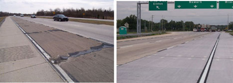
Before rehabilitation (left); After rehabilitation (right).
Schedule of Events
March
13-15 NRMCA 2009 Concrete Technology Forum, Cincinnati, OH
21-25 ACI Spring Convention, Chicago, IL
April
6-8 CP Tech Center Technology Transfer Concrete Consortium and National Concrete Consortium, Savannah, GA
8-9 FHWA Bridge Engineering Conference, Orlando, Florida
13-15 Concrete Sustainability Conference Temple, Arizona
May
9-12 International Symposium on Cement and Concrete, Jinan, China
Technical Editor: Dr. Michael Thomas
Managing Editor: Bebe Resendez
FHWA Contact: Gina Ahlstrom, Concrete Pavement Engineer (Gina.Ahlstrom@dot.gov). FHWA-Office of Pavement Technology
Editorial Committee: Lizanne Davis (FMC Corporation), Steve Lane (Virginia DOT), Colin Lobo (National Ready Mix Concrete Association), Brian Merrill (Texas DOT), Peter Taylor (CP Tech Center), Paul Tennis (Portland Cement Association), Leif Wathne (American Concrete Pavement Association)
Get On the Reactive Solutions Mailing List
Want to subscribe to future issues? Email us at asrnewsletter@transtec.us. — Subscriptions are free.