

Technical Advisory T 5040.29 Paved Shoulders
February 2, 1990
Par.
- Purpose
- Cancellation
- Definition
- Background
- Shoulder Type Selection
- Design
- Common Distresses
- Summary
- References
- Figures
- PURPOSE. To outline recommended practices for the design of paved shoulders.
- CANCELLATION. Technical Advisory T 5040.18, Paved Shoulders, dated July 29, 1982.
- DEFINITION. Shoulder - the portion of the roadway contiguous with the traveled way for accommodation of stopped vehicles for emergency use, and for lateral support of the base and surface courses.
- BACKGROUND
- Over the years, the function of shoulders adjacent to mainline pavements has broadened considerably. Some of the added functions of modern roadway shoulders are: toaccommodate an increasing encroachment of traffic; to expedite water runoff from travel lane pavement; to provide added space for construction and maintenance activities; to provide other usage such as bicycle paths or slow-moving vehicles and equipment lanes; to reduce edge stresses and edge and corner deflections; and to reduce the development of pavement edge dropoffs.
- Paved shoulders are required on all Interstate routes. The decision to pave a shoulder on other routes is an engineering determination based on traffic volume, past experience and availability of funds. Paved shoulders are justified by improved and smoother traffic operations, expectation of better pavement performance, increased pavement life, enhanced highway safety and reduced maintenance. Studies included in TRB Special Report 214, "Designing Safer Roads - Practices for Resurfacing, Restoration, and Rehabilitation" and Publication No. FHWA/RD-87/094, "Safety Cost-Effectiveness of Incremental Changes in Cross-Section Design - Informational Guide" have cited reduced accident rates with the use of paved shoulders.
- SHOULDER TYPE SELECTION
- It is recommended that the shoulder be constructed of the same materials as the mainline pavement in order to facilitate construction, improve pavement performance and reduce maintenance costs.
- The use of full-width paved shoulders is desirable. However, the additional cost of this design may not be warranted on all projects. In those cases, the use of widened lanes should be given strong consideration. Widened lanes reduce edge stresses and the potential for edge drop-offs, increase safety, and reduce maintenance costs. A monolithic widening of 2 to 3 feet outside of the traveled way is recommended. Widened lanes are only effective when striped as 12-foot travel lanes. Consideration should be given to the placement of rumble strips on the shoulder portion of the widened lane.
- DESIGN
- General
- (1) Background. The structural design of shoulders has received less attention than the mainline pavement. Shoulder design has developed gradually through experience rather than from a rational pavementdesign approach. There are currently no nationally recognized procedures for designing shoulders. When designing a shoulder, the following should be considered:
- (a) Consider whether the shoulder will be used as a temporary or permanent traffic lane in the future.
- (b) Integrate shoulder drainage with the overall pavement subdrainage design.
- (c) Avoid the use of aggregate base courses having more than 6 percent minus 200 mesh sieve materials to prevent frost heaving, pumping, clogging of the shoulder drainage system, and base instability.
- (d) Have a definite program of shoulder mainte-nance.
- (e) Take advantage of the desirable performance of concrete shoulders adjacent to concrete mainline pavements.
- (2) Width and Cross-Slope. Documents containing applicable geometric criteria are listed in Federal-Aid Highway Program Manual 6-2-1-1, "Design Standards for Highways." The shoulder cross-slope should be at least 1 percent more than the mainline pavement cross-slope on tangent sections to facilitate drainage but should not be so steep as to preclude the use of the shoulder as a temporary travel lane during future construction. Asphalt and concrete shoulders should be sloped from 2 to 6 percent, gravel or crushed rock from 4 to 6 percent and turf about 8 percent. However, care must be exercised so that the algebraic difference in cross-slope at the pavement edge does not exceed 0.08 in order to avoid a hazardous rollover effect.
- (3) Pavement Markings and Shoulder Texture Treatments
- (a) Distinguishing paved shoulders from the mainline pavement is recommended to discourage the use of the shoulder as a travel lane and provide guidance and warning to drivers. This can be accomplished by pavement markings and differences in shoulder surface texture.
- (b) Shoulder texture treatments that provide an audible/vibrational warning to errant drivers have proven effective in keeping traffic off the shoulder and reducing accidents on long tangent or monotonous highway sections with a history of run-off-the-road accidents. Attachment 1 (Figures 1 through 3) describes treatments used by States on bituminous and concrete shoulders.
- (4) Drainage. The presence of free water beneath the pavement and/or shoulder is detrimental to performance. Grooved shoulder texture treatments, such as discussed in paragraph 6a(3)(b), can affect surface drainage. It is recommended that these treatments be offset from the longitudinal lane/shoulder joint to facilitate point sealing and minimize surface water infiltration. An analysis to provide adequate surface and subsurface drainage should be conducted on each project.
- (1) Background. The structural design of shoulders has received less attention than the mainline pavement. Shoulder design has developed gradually through experience rather than from a rational pavementdesign approach. There are currently no nationally recognized procedures for designing shoulders. When designing a shoulder, the following should be considered:
- Concrete Shoulders
- (1) General
- (a) Concrete shoulders should be tied to the mainline with properly spaced and sized tiebars. Tied concrete shoulders will reduce pavement stresses and edge deflections. Tied concrete shoulders will also result in a tighter, easier to seal longitudinal joint that, when properly maintained, will effectively reduce water infiltration into the pavement structure.
- (b) Retrofitting tied concrete shoulders or lane widening will reduce edge stresses and deflections. The age, condition and remaining service life of the existing pavement play a significant role in determining whether a retrofit is practical. It is recommended that aretrofit be added only when an engineering and economic analysis indicates it to be a cost-effective solution.
- (2) Thickness
- (a) Shoulders should be structurally capable of withstanding wheel loadings from encroaching truck traffic. On urban freeways or expressways, the shoulders should be constructed to the same structural section as the mainline pavement to ensure adequate load capacity at the interface between the mainline and shoulder; to provide for ease and economy of construction; and to prevent a "bathtub" condition under the pavement. This will also allow the shoulder to be used as a temporary detour lane during rehabilitation or reconstruction.
- (b) As an option for other than urban freeways and expressways, a tapered shoulder may be considered. Adjacent to the mainline, the shoulder should be the same thickness as the mainline to permit mid-depth tiebar placement and to provide structural support for truck wheel encroachments. The shoulder may then be tapered to no less than 6 inches at the outside edge. Care must be exercised with a tapered section since a "bathtub" type condition can result, ponding water in the area of the lane/shoulder interface.
- (3) Subbase. It is recommended that the same type of subbase be used under the shoulder as under the mainline, especially on high-volume facilities. Care must be taken in designing the subbase cross-slope under concrete shoulders to avoid pocketing of water under the lane/shoulder joint and at the shoulder edge. Problems are often encountered at this location due to changes in subbase type,resulting in nonuniform support or difference in drainage characteristics.
- (4) Transverse Joint
- (a) Mainline pavement joints should be extended across the shoulder. All transverse shoulder joints should be sawed to a depth of 1/3 the slab thickness.
- (b) Where plain jointed concrete shoulders are used adjacent to continuously reinforced mainline pavement, the shoulder joints should be sawed at 15-foot intervals. Plain concrete shoulders should not be constructed integrally with continuously reinforced concrete pavement. Transverse saw cuts in the integrally constructed shoulders will propagate cracks across the mainline.
- (c) Where plain jointed concrete shoulders are used adjacent to jointed reinforced mainline pavement with skewed joints, intermediate joints should not be sawed in the shoulder. Skewed intermediate shoulder joints tend to propagate two parallel transverse cracks across the mainline pavement.
- (d) Where plain jointed concrete shoulders are used adjacent to jointed reinforced mainline pavement with perpendicular joints, intermediate shoulder joints are optional. However, intermediate joints should not be sawed if the shoulder is constructed integrally with the mainline pavement. Intermediate transverse saw cut in integrally constructed shoulders will propagate cracks across the mainline.
- (5) Longitudinal Joint. Combined lane and shoulder or lane widening widths of 15 feet for the right (outside) lane and 16 feet for the left (inside) lane have generally performed satisfactorily. For widths greater than these, a longitudinal joint should be sawed and sealed.
- (6) Keyway. Keyways are not recommended for use, and should never be used for pavements less than 10 inches thick. If used for pavements 10 inches or greater in thickness, keyways should be placed at mid-slab depth to ensure maximum strength. Properconcrete consolidation, both above and below the keyway, is essential.
- (7) Tiebars
- (a) Tiebars are needed between the mainline pavement and concrete shoulders to keep the longitudinal joint tight so as to provide the necessary load transfer. Tiebars are typically placed on 30-inch centers at mid-slab depth. If tiebars are to be bent and later straightened during construction, Grade 40 steel is recommended, as it better tolerates the bending. When using Grade 40 steel, 5/8-inch by 30-inch tiebars should be used. When using Grade 60 steel, 5/8-inch by 40-inch or 1/2-inch by 32-inch tiebars should be used. These lengths are necessary to develop the allowable working strength of the tiebar.
- (b) Tiebars should not be placed within 15 inches of transverse joints. When using tiebars longer than 32 inches with skewed joints, tiebars should not be placed within 18 inches of the transverse joints.
- (c) The structural adequacy of tiebars can be reduced through corrosion. Corrosion resistant tiebars are recommended.
- (8) Reinforcement. The majority of concrete shoulders are plain with short joint spacing. They have performed well when placed adjacent to either plain jointed, reinforced jointed, or continuously reinforced concrete mainline pavements. The plain jointed design is therefore recommended. In cases where jointed reinforced or continuously reinforced shoulders are placed integrally with the same type of mainline pavement, the steel in the shoulder is normally placed at the same percentage as requiredfor the mainline pavement.
- (9) Lane Widening. A 2- to 3-foot integral widening of the mainline slab will reduce edge strains and deflections. To be effective, the travel lane should be striped at 12 feet with the edge of the slab being moved into the shoulder and away from traffic load applications. The remaining portion of the shoulder may also be paved.
- (1) General
- Flexible Shoulders
- (1) Types
- (a) Bituminous surface treated shoulders consist of an aggregate shoulder on which coats of liquid bituminous material and aggregate chips have been applied and rolled. Regional terminology such as armor coat, double or triple surface treatment, or seal coat all apply.
- (b) Bituminous aggregate shoulders consist of a bituminous mat on top of an aggregate base course of variable depth that may or may not contain a stabilizing agent.
- (c) Full-depth asphalt shoulders consist of asphalt mixtures for all courses laid directly on the prepared subgrade.
- (d) Widened lanes consist of a 2- to 3-foot widening of the mainline structural section with the remaining width of shoulder composed of a bituminous surface treatment, bituminous aggregate section, aggregate or turf. For the widening to be effective, the widened lane should be striped as a 12-foot travel lane.
- (2) Thickness
- (a) Shoulders should be structurally capable of withstanding wheel loadings from encroaching truck traffic. On urban freeways or expressways, the shoulders should be constructed to the same structural section as the mainline pavement to ensure adequate load capacity at the interface between the mainline and shoulder; to provide for ease and economy of construction; and to prevent a "bathtub" condition under the pavement. This will alsoallow the shoulder to be used as a temporary detour lane during rehabilitation or reconstruction.
- (b) For other than urban freeways and expressways, a structural section less than that of the mainline may be warranted. It is recommended that the thickness be based on an evaluation of life-cycle costs and past performance under similar conditions. The use of widened lanes should be considered in the life-cycle cost analysis.
- (1) Types
- General
- COMMON DISTRESSES
- Most shoulder deterioration is attributable to one or more of the following causes: truck encroachments, water intrusion at the longitudinal joint, use of lower quality materials, and inadequate thickness.
- Field observations have shown that shoulder distress is primarily concentrated within 24 inches of the longitudinal mainline/shoulder joint.
- The longitudinal joint between a concrete mainline pavement and a flexible shoulder is a primary source for infiltration of surface water into the subbase. The longitudinal joint has proven to be one of the weakest parts of the mainline/shoulder system. Distress in the form of excessive cracking, breakage, and settlement is concentrated at this location. Separations generally range from 1/8 to as much as 2 inches. The infiltration of water can be minimized by a properly sealed and maintained joint. Some highway agencies add a "wedge" (6 to 19 inches wide) of hot-mixed bituminous material in the low areas where the flexible shoulder has settled. Tied concrete shoulders in lieu of flexible shoulders will minimize the problem associated with a longitudinal joint.
- 8.SUMMARY. Shoulders are an important element in theperformance and overall service provided by highway pavements. Proper attention to the selection, design, construction and maintenance of shoulders is an important part of pavement management and can result in improved performance and service cost effectiveness.
- 9.REFERENCES. Attachment 2 lists reference documents that should prove useful in the area of design, construction and rehabilitation of paved shoulders.
- 10.FIGURES. Attachment 1 (below) contains three figures which describe shoulder surface treatments used by States on bituminous and concrete shoulders.
Thomas O. Willett
Acting Associate Administrator
for Engineering and
Program Development
Attachments
Attachment 1: Typical Shoulder treatments
Figure 1
Bituminous Shoulders
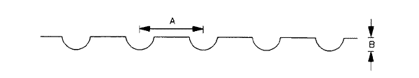
Figure 1. Indented Strip - A continuous stretch of indentations is impressed in the shoulder through the use of a steel roller. In a method developed by California, steel bars are welded to a vibratory roller to impress indentations. Georgia specifies that a nominal 1 and ½ inch diameter pipe be welded to the roller drum to form the indentations. Typically the indentations are spaced 8 inches apart (A) and 3/4 inch to 1 inch deep (B). Most States offset this treatment 6 to 12 inches from the edge of the mainline pavement and the typical treatment width is 3 feet.
| STATE | Appl | 1 | 3/4" | 1/2" | 3/8" | #4 | #8 | #16 | #100 | #200 | #/SY |
|---|---|---|---|---|---|---|---|---|---|---|---|
| NC | 1st | 90-100 | 20-55 | 0-10 | 0-5 | --- | --- | --- | --- | 0-1.5 | 45-50 |
| 2nd | 100 | 90-100 | 20-55 | 0-15 | 0-5 | --- | --- | --- | 0-1.5 | 35-40 | |
| 3rd | --- | 100 | 98-100 | 75-100 | 20-95 | 0-15 | --- | --- | 0-1.5 | 17-22 | |
| SC | 1st | 100 | 90-100 | --- | 0-20 | 0-5 | --- | --- | --- | --- | 28-32 |
| 2nd | --- | 100 | 95-100 | 80-100 | 20-50 | --- | 0-6 | 0-2 | --- | 18-22 |
Figure 2. Bituminous Surface Treatment - The effectiveness of a textured shoulder is largely dependent upon the gradation of aggregate used. Treatments containing 3/4 inch to 1 inch stone have been observed to be very effective as an alerting texture.
Figure 3
Concrete Shoulders
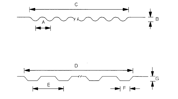
Figure 3. Corrugations or rumble strips - The top configuration is the one most commonly used. Most States build this type of section 3 to 6 feet wide (C); 3 to 4 and ½ inches between corrugations (A); and 1 inch deep (B). Corrugations generally extend the full width of the shoulder and are placed at 40 to 100 foot intervals. One variation of this treatment is to offset the section ½ to 4 feet from the edge of mainline pavement. The corrugations may also be placed in the middle 1/3 of the shoulder, if desired, to accommodate traffic during future rehabilitation or maintenance work or to accommodate bicyclists.
The bottom configuration is generally built 4 feet wide (D); 6 to 12 inches between corrugations (E); and 3/4 to 1 inch deep (G). Corrugations are generally offset ½ to 2 feet from the edge of the mainline pavement and are placed at 40 to 90 foot intervals.
Attachment 2
References
1. "AASHTO Guide for Design of Pavement Structures, 1986," American Association of State Highway and Transportation Officials.
2. "Design and Use of Highway Shoulders," National Cooperative Highway Research Program Synthesis Number 63, August 1979.
3. "Design Practices for Paved Shoulders," Transportation Research Board 594, 1976, R. G. Hicks, Richard D. Barksdale and Donald K. Emery.
4. "State-of-the-Art Review of Paved Shoulders," Transportation Research Record 594, 1976, J. M. Portigo.
5. "Thickness Design - Asphalt Pavements for Highway and Streets," The Asphalt Institute, Manual Series No. 1, September 1981.
6. "Current Practices in Shoulder Design, Construction Maintenance and Operations," Highway Research Circular Number 142, April 1973.
7. "Design of Zero-Maintenance Plain Jointed Concrete Pavement," FHWA-RD-77-111, June 1977, Michael I. Darter.
8. "Structural Analysis and Design of PCC Shoulders," FHWA-RD-81-122, April 1982, Jihad S. Sawan, Michael I. Darter, and Barry J. Dempsey.
9. "What We Have Learned to Date from Experimental Concrete Shoulder Projects," Highway Research Record 434, Edwin C. Lokken, 1973.
10. "Portland Cement Concrete Shoulder Performance in the United States (1965-1980)," Proceedings, 2nd International Conference on Concrete Pavement Design, Charles Slavis, 1981.
11. "Concrete Shoulders for CRC Pavements," Proceedings, Continuously Reinforced Concrete Pavement Workshop, FHWA-78-80-231, June 1980, Gordon Ray.
12. "Improved Pavement-Shoulder Joint Design," National Cooperative Highway Research Program Report 202, Richard D. Barksale and R. G. Hicks.
13. "Paved Highway Shoulder and Accident Experience," Transportation Engineering Journal of ASCE, Volume 100, 1974, C. L. Heimbach, W. W. Hunter, and G. C. Chao.
14. "A Policy on Geometric Design of Highways and Streets, 1984," American Association of State Highway and Transportation Officials.
15. "Design and Performance of Highway Shoulders," Kentucky Research Report UKTRP-87-8, David Q. Hunsucker, Gary W. Sharpe and Robert C. Deen.
16. "Shoulder Geometrics and Use Guidelines," National Cooperative Highway Research Program Report 254, Hugh G. Downs, Jr., and David W. Wallace.
17. "Structural Design of Roadway Shoulders," FHWA/RD-86/089, Kamran Majidzadeh and George J. Ilbes.