U.S. Department of Transportation
Federal Highway Administration
1200 New Jersey Avenue, SE
Washington, DC 20590
202-366-4000
A Summary of Vehicle Detection and Surveillance Technologies use in Intelligent Transportation SystemsChapter 3 - Overview of Vehicle Detection and Surveillance TechnologiesSensors used for vehicle detection and surveillance may be described as containing three components, the transducer, a signal processing device, and a data processing device. The transducer detects the passage or presence of a vehicle or its axles. The signal-processing device typically converts the transducer output into an electrical signal. The data-processing device usually consists of computer hardware and firmware that converts the electrical signal into traffic parameters. Typical traffic parameters include vehicle presence, count, speed, class, gap, headway, occupancy, weight, and link travel time. The data processing device may be a part of the sensor, as with devices that produce serial output data, or may be controllers external to the sensor as utilized with sensors that have optically-isolated semiconductor or relay outputs. The following chapters describe the operating principles, sensor measurement accuracies, costs, advantages, and disadvantages of technologies that find application in in-roadway and over-roadway sensors. The in-roadway and over-roadway terminology is that used in the Traffic Detector Handbook published by the U.S. Federal Highway Administration ( Klein , et al., 2006). Each technology section also contains equipment-specific data supplied by the manufacturers or vendors of representative sensors. In-roadway sensorsAn in-roadway sensor is one that is either
Examples of in-roadway sensors include inductive loop detectors, which require sawcuts in the pavement; weigh-in-motion sensors, which are embedded in the pavement; magnetometers, which may be embedded or placed underneath a paved roadway or bridge structure; and tape switches, microloops, pneumatic road tubes, and piezoelectric cables, which are mounted on the roadway surface. The operation of most of these sensors is well understood as they generally represent applications of mature technologies to traffic surveillance. The drawbacks to their use include disruption of traffic for installation and repair and failures associated with installations in poor road surfaces and use of substandard installation procedures. Resurfacing of roadways and utility repair can also create the need to reinstall these types of sensors. Over-roadway sensorsAn over-roadway sensor is one that is mounted above the surface of the roadway either
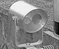
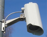
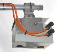
Examples of over-roadway sensors are video image processors (i.e., machine vision based sensors) that utilize cameras mounted on poles adjacent to the roadway, on structures that span the roadway, or on traffic signal mast arms over the roadway; microwave radar sensors mounted adjacent to the roadway or over the lanes to be monitored; ultrasonic, passive infrared, and laser radar sensors normally mounted over the lanes to be monitored (some passive infrared models can be mounted adjacent to the roadway); and passive acoustic sensors mounted adjacent to the roadway. Some emerging applications for wide area surveillance envision over-roadway sensors mounted on tall buildings and radio towers near the roadway and on aerial platforms. Recent evaluations have shown that modern over-roadway sensors produce data that meet the requirements of many current freeway and surface street applications (Klein and Kelley, 1996; Kranig J., E. Minge, and C. Jones, 1997; MnDOT, 2002; Middleton, D. and R. Parker,2002). Similar to in-roadway sensors, the over-roadway sensors provide vehicle count, presence, and passage. However, many also provide vehicle speed, vehicle classification, and multiple-lane, multiple-detection zone coverage. Some over-roadway sensors incorporate more than one technology. Figure 1 displays sensors that combine passive infrared with ultrasound andDoppler microwave radar. The passive infrared-ultrasound combination provides enhanced accuracy for presence and queue detection, vehicle counting, and height and distance discrimination. The passive infrared-Doppler microwave radar sensor is designed for presence and queue detection, vehicle counting, speed measurement, and length classification. The Doppler microwave radar sensor measures high to medium speeds and the passive infrared measures vehicle count, presence, and occupancy. At medium speeds, the multiple detection zone passive infrared sensor automatically calibrates its speed measurements against the radar's. This calibration permits the infrared to measure slow vehicle speeds and detect stopped vehicles. The passive infrared-microwave radar sensor combination may also be utilized to detect wrong-way drivers. The triple technology infrared-Doppler radar-ultrasound sensor provides vehicle classification, vehicle counts and speed, presence and queue detection, occupancy and time gap data, and travel direction.
Figure 1. Combination technology sensors. (Photographs courtesy of ASIM Technologies, Uznach , Switzerland ). Relative Cost of SensorsA satisfactory cost comparison between various sensor technologies can only be made when the specific application is known. For example, a relatively inexpensive ultrasonic, microwave, or passive infrared sensor may seem to be the low-cost choice at first glance for instrumenting a surface street intersection if inductive loop detectors are not desired. But when the number of sensors needed is taken into account along with the limited amount of directly measured data that may be available (e.g., speed is not measured directly by a single zone infrared sensor), a more expensive sensor such as a video image processor (VIP) may be the better choice. Consequently, if it requires twelve to sixteen conventional inductive loop detectors (or ultrasonic, microwave, infrared, etc. sensors) to fully instrument an intersection, the cost becomes comparable to that of a VIP. Furthermore, the additional traffic data and visual information made available by the VIP may more than offset any remaining cost difference. In this example, the VIP is assumed to meet the other requirements of the application, such as the desired 100 percent detection of vehicles at the intersection. Similar arguments can be made for freeway applications using multiple sensors and requiring information not always available from the less expensive sensors. Microwave presence-detecting radar mounted in a side-looking configuration may be another cost-effective replacement for in-roadway sensors. Presence-detecting radar sensors can monitor multilane freeway traffic flow and surface street vehicle presence and speed. In these applications, the microwave sensors replace a greater number of inductive loop detectors that are needed in the travel lanes. Furthermore, the microwave sensor potentially provides direct measurement of speed at a greater accuracy than provided by the loops. Other factors that affect the cost and selection of sensors are the need for road closure for installation and maintenance, maturation of the designs and manufacturing processes for sensors that use the newer technologies, reduced prices through quantity buys, and availability of mounting locations and communications links at the application site. In some urban areas, the cost of trenching in the street and restoration for lead-in wire and cable to connect to a controller cabinet is very high, e.g., $50 per foot (0.3 m) or more. Trenching thus becomes a significant part of the installation cost. In these cases, over-roadway sensors that utilize an RF, microwave, or spread spectrum radio links may be the low-cost alternative to gather and transmit sensor data to the controller. Sensor Technology ComparisonTable 1 compares the strengths and weaknesses of the sensor technologies that will be discussed in the following chapters with respect to installation, parameters measured, performance in inclement weather and variable lighting conditions, and suitability for wireless operation. Most over-roadway sensors are compact and not roadway invasive, making installation and maintenance relatively easy. Some installation and maintenance applications may require the closing of the roadway to normal traffic to ensure the safety of the installer and motorist. All the sensors discussed operate under day and night conditions, although video-image processors may show improved performance at night when some street lighting is available (D. Bullock, 2002). Table 2 lists the types of data typically available from each sensor technology, coverage area, communication bandwidth requirements, and purchase costs. Several technologies are capable of supporting multiple lane, multiple detection zone applications with one or a limited number of units. These devices may be cost effective when larger numbers of detection zones are needed to implement the traffic management strategy. The communication bandwidth is low to moderate if only data and control commands are transmitted between the sensor, controller, and traffic management center. The bandwidth is larger if real-time video imagery is transmitted at 30 frame/s. The requirement for large bandwidth communications media such as T1 telephone lines, which support transmission rates of 1.544 X 106 bits/s or baud at a bandwidth of 125 MHz, and fiber can be reduced if compressed imagery (e.g., transmission rates of 256,000 bit/s at a bandwidth of 20.5 MHz) is suited for the application. The required transmission rate increases when large numbers of sensors, roadside information devices such as changeable message signs and highway advisory radio, signal timing plans, and traveler information databases are used to implement traffic management strategies. Table 1. Strengths and weaknesses of commercially available sensor technologies ( Klein , 2001; Rhodes , 2005; Klein , et al., 2006).
Table 1 (continued). Strengths and weaknesses of commercially available sensor technologies.
Table 2. Traffic output data (typical), communications bandwidth, and cost of commercially available sensors ( Klein , 2001).
a Installation, maintenance, and repair costs must also be included to arrive at the true cost of a sensor solution as discussed in the text. b Speed can be measured by using two sensors a known distance apart or estimated from one sensor and the effective detection zone and vehicle lengths. c With specialized electronics unit containing embedded firmware that classifies vehicles. d With special sensor layouts and signal processing software. e With microwave radar sensors that transmit the proper waveform and have appropriate signal processing. f With multi-detection zone passive or active mode infrared sensors. g With models that contain appropriate beamforming and signal processing. h Depends on whether higher-bandwidth raw data, lower-bandwidth processed data, or video imagery is transmitted to the traffic management center. i Includes underground sensor and local detector or receiver electronics. Electronics options are available to receive multiple sensor, multiple lane data. The range of purchase costs shown for a particular sensor technology reflects cost differences among specific sensor models and capabilities. If multiple lanes are to be monitored and a sensor is capable of only single lane operation, then the sensor cost must be multiplied by the number of monitored lanes. Direct purchase cost is not the only cost associated with a sensor. Installation, maintenance, and repair should also be factored into the sensor selection decision. Installation costs include fully burdened costs for technicians to prepare the road surface or subsurface to install the sensor and mounting structure (if one is required), close traffic lanes where required, and verify proper functioning of the device after installation is complete. Maintenance and repair estimates may be obtained from manufacturers and from other agencies and localities that have deployed similar sensors. The technologies listed in Table 2 are mature with respect to traffic management applications, although some may not provide the data required for a specific application. Some technologies, such as video image processing, continue to evolve by adding capabilities that measure additional traffic parameters, track vehicles, or link data from one camera to those from another. Inductive loop detectors continue to be widely used to monitor traffic flow and control signals because of their relatively low cost, maturity, aesthetics, and policy issues. Some of the over-roadway sensor technologies, such as video image processing, multizone microwave radar, and passive infrared sensors, can replace several inductive loops. In these applications, the higher cost of the over-roadway sensor technologies can offset the costs associated with installing and maintaining multiple inductive loops. The mounting location is critical to the selection and proper operation of a traffic sensor. Experience by state DOTs has indicated that suitable mounting locations must be available with the proper elevation and proximity to the roadway in order for above- roadway sensors to function properly. Sensors selected for a first time application should be field tested under actual operating conditions that include variations in traffic flow rates, day and night lighting, and inclement weather. The operation and applications of the following vehicle detection and surveillance technologies are discussed in the following chapters:
|
|||||||||||||||||||||||||||||||||||||||||||||||||||||||||||||||||||||||||||||||||||||||||||||||||||||||||||||||||||||||||||||||||||||||||||||||||||||||||||||||||||||||||||||||||||||||||||||||||||||||||||||||||||||||||||