U.S. Department of Transportation
Federal Highway Administration
1200 New Jersey Avenue, SE
Washington, DC 20590
202-366-4000
Puerto Rico and US Virgin Islands Division
Documentation Report
Replacement of Bridge #1
Over San Antonio Channel
San Juan, Puerto Rico
June 2002
Prepared by
Eddie Rivera, Highway Safety Engineer
Rosana Aguilar - Civil Engineering Student
Damaris Santiago - Civil Engineering Student
Federal Highway Administration
Puerto Rico Division Office
Federal Building, Room 329
Carlos Chardón Street
San Juan, PR 00918
Index
The purpose of this report is to document the installation procedure of a tubular steel bridge rail by the Puerto Rico Highway and Transportation Authority (PRHTA). This report could be use as a reference for future steel bridge railing installations. The design of this bridge rail was developed by the Washington, DC Department of Public Works, in cooperation with the Federal Highway Administration (FHWA), in order to attend roadside safety concerns on historic bridges. This bridge rail system is known as the Washington, DC Historic Bridge Rail, see Drawing 1.1. See Attachment B for complete Standard Drawing. This bridge rail is aesthetically pleasing for use with bridges on highways through historic areas.
The bridge over San Antonio Channel is located at the entrance of the historic area of San Juan, Puerto Rico. The original bridge was constructed in 1925, and became deteriorated by the environment conditions, like exposure to marine conditions and heavy loads. When the PRHTA decided to replace the original bridge they consulted the FHWA Puerto Rico Division. It was important to consider the roadside safety and aesthetics of the new bridge during the design process. The FHWA recommended the use of the Washington, DC Historic Bridge Rail to enhance the bridge aesthetics and safety. This bridge rail satisfied both design criteria, aesthetic requirements and highway safety standards.
The PRHTA contracted Las Piedras Construction Corporation (from Las Piedras, PR) to replace the existing bridge #1. The Contractor hired Engineering Design International of Florida (from Miami, FL) for the fabrication of the bridge rail sections. The bridge rail was installed during the spring of 2002.
This report could be a helpful reference document for future projects involving historic bridges. The lessons learned and recommendations included on this report could be used as a reference during the design and construction process on similar bridges.
Drawing 1.1. WASHINGTON DC HISTORIC BRIDGE RAIL CURB MOUNTED RETROFIT
Cross Section
(PDF, 63 Kb)
Longitudinal barriers (including bridge railing) installed on the National Highway System (NHS) must comply with NCHRP 350 crash testing criteria. The Washington, DC Historic Bridge Rail was crash tested; see Appendix A-Crash Test Report for additional information. The crash test performed is equivalent to NCHRP 350 (Test Level -2).
The bridge replacement construction plans included a bridge rail standard drawing. This standard drawing included details for the typical section and end sections. These details (front view, top view, and cross sections) are standard. See Appendix C-Historic Bridge Rail Standard Drawings for additional information.
Using the Historic Bridge Rail Standard Drawings as a guide, the Contractor ordered the custom design and fabrication of the bridge rail at a metal shop located outside the island (Miami, FL). The following firm prepared the shop drawings and manufactured the bridge railing sections:
Engineering Design International of Florida (EDI), Inc.
9200 SW 80th Terrace
Miami, Florida 33173
Telephone: 305-596-6643
Due to the unique bridge rail design and the geometry of the bridge deck, this bridge rail was custom built by experienced steel workers. EDI prepared detailed shop drawings depicting each section using the standard drawing included on the project construction plans. During the bridge rail design EDI considered the bridge geometry (horizontal and vertical alignments).
The fabrication of this type of rail represents a challenge for any steel worker and welder. The long and continuous welding of the box beams can cause the bridge rail to warp significantly due to the change in temperature. On previous projects in the Washington, DC area, welders had to use a heat treatment (and a sledge hammer) to the top of the beam elements in order to straighten them out after warping occurred due to the long welding. However, EDI built a jig that eliminated the warping problem. This jig holds the steel elements tight during welding operations, avoiding warping.
Finally, the sections were finished with a hot dipped galvanized treatment to protect them from corrosion. Each section had a unique identification number stamped at the base for identification purposes (see Figures 4-5). The shop drawings depicted the exact location of each section according to the position from the center of the bridge to the end of it. This identification ensures the correct position of the sections in the field assembly.
4.1. Curb and Concrete Sidewalk Construction
The Contractor ordered the fabrication of the bridge rail at a metal shop located outside the island. Due to the unique design and the geometry of the bridge deck, this bridge rail was custom built by experienced steel workers. The metal shop prepared detailed shop drawings depicting each section using the standard drawing included on the project construction plans.
While the railing was under construction, the Contractor started the construction of the curbs and the concrete sidewalks (see Figure 1).
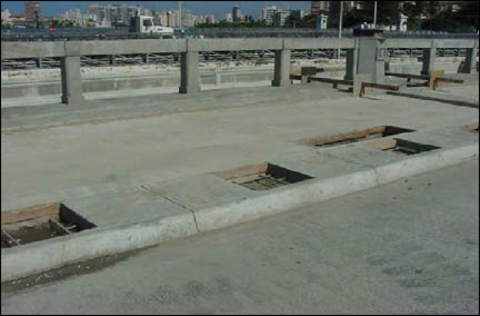
Figure 1. Concrete sidewalk and curb, Bridge #1 over San Antonio Channel
The bridge rail standard drawing included on the construction plan (see Drawing 1.1), called for the sidewalk to be completed before the rail is installed; then partially demolished (chip out) to place the rail post; and finished again. The Contractor did not like the alternative of partially demolishing (just finished) sidewalks and decided for a different alternative.
Rather than partially demolishing the sidewalk, he left open rectangular spaces for the anchorage of the base plates of the bridge rail sections. These spaces have dimension of 24 in x 24 in (see Figure 2). For a detail of the curb and sidewalk, see Drawing 4.1.
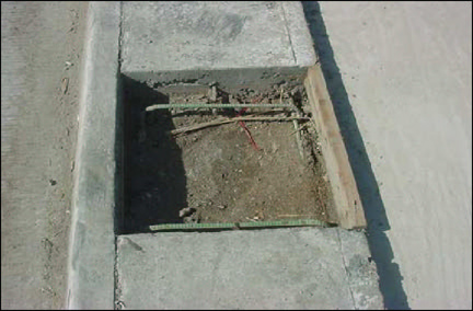
Figure 2. Open rectangular spaces left for the anchorage of the base plates
Drawing 4.1. BRIDGE RAIL SECTION
BRIDGE OVER SAN ANTONIO CHANNEL
CURB MOUNTED RETROFIT
Cross Section
(PDF, 157 Kb)
4.2. Bridge Rail Preliminary Location
The bridge rail sections were placed near the open rectangular spaces for the preliminary location (see Figure 3). Every section had been identified in the shop drawings according to its corresponding position in the bridge. These identification codes have a nomenclature that shows the position and the section number from the beginning toward the center of the bridge. The identification codes were stamped at the base of each section. For example, the section identified as NW2 corresponds to the Northwest side of the bridge, and the section is the second one from the beginning of the bridge (see Figure 4). For the end sections, the bridge rail sections had been identified differently. For example, the section identified as ESW4 corresponds to the Southwest extension, and the section is the fourth one from the beginning of the transition part toward the beginning of the bridge (see Figure 5).
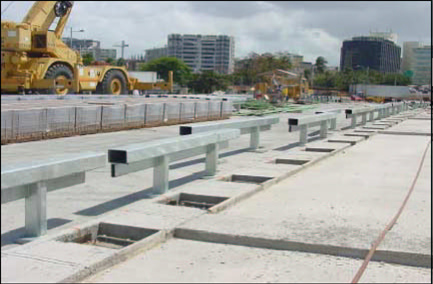
Figure 3. Back side view of the bridge rail preliminary location
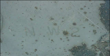
Figure 4. Bridge rail section that corresponds to the Northwest direction and position number 2
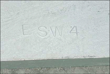
Figure 5. Extension section number 4 that corresponds to the Southwest part of the bridge
4.3. Dry Fitting and Marking of Pilot Holes
The bridge rail sections were set in place for the preliminary fitting using a crane. Each bridge rail section is connected to each other by inserting a joint sleeve. This joint sleeve is welded on one side only, and let free on the other. Due to this connection design, the Contractor was not able to install section by section easily. In order to fit just one section, the Contractor had to handle and fit adjacent sections at the same time. Consequently, the Contractor dry fitted the entire bridge rail on one side of the bridge in order to mark the pilot holes (see Figures 6-7).
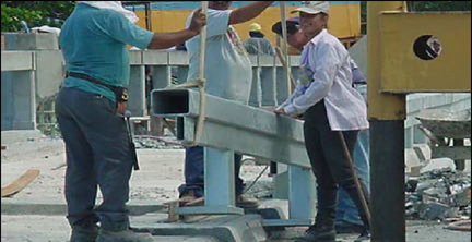
Figure 6. The bridge rail section was dry fitted to mark the pilot holes
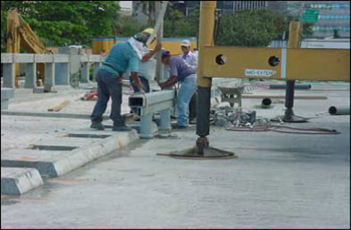
Figure 7. The bridge rail section was dry fitted to mark the pilot holes
During the dry fitting, the Contractor realized that providing the 3 in offset from the curb's bottom edge to the bridge rail face was not possible because the curb was in the way (see Figures 8-9).
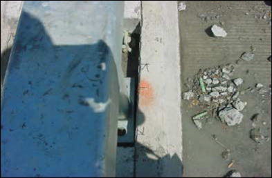
Figure 8. Front side view of the bridge rail placement
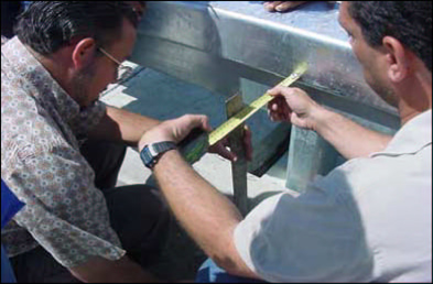
Figure 9. The Contractor verified the distance between the bottom edge of the curb and the face of the bridge rail.
Consequently, the Contractor demolished the curbs. He used a saw cut machine (see Figures 10-11)
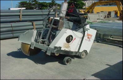
Figure 10. A saw cut machine was used to cut some parts of the curbs
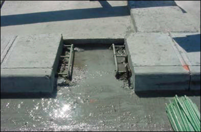
Figure 11. Front view of the saw cut curb
After the entire section of bridge rail was dry fitted correctly, the Contractor use spray paint to mark the pilot holes (see Figure 12).
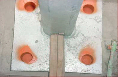
Figure 12. The pilot holes were marked with spray paint
After all the pilot holes were marked, the bridge rail sections were removed to drill the pilot holes for the anchor bolts. Every hole was drilled using an impact hammer drill with carbide drill bit (see Figure 13). The depth required for the pilot holes was 8 in. The diameter of the pilot holes is 1/2 in bigger than the diameter of the anchor bolts. The anchor bolts were embedded with epoxy to maximize the anchorage.
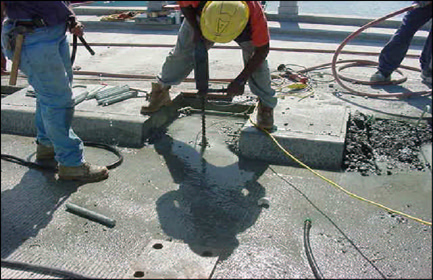
Figure 13. The impact hammer drill with carbide drill bit was used to drill the pilot holes
Sometimes, the workers hit reinforcing bars while they were drilling the pilot holes (see figure 14). The structural effect of cutting the reinforced bars is negligible. These bars are not subjected to direct loading and the removed sections are relatively small compared with the entire structure. When this happened, the workers had to change the drill. In order to cut through reinforcing bars, they used an industrial drill with a diamond core bit (see Figures 15-17). Figure 18 shows the pilot holes completed.
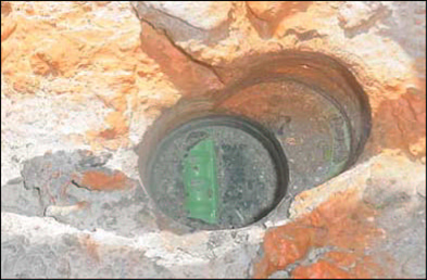
Figure 14. Steel bar of the deck found when drilling the 1 1/2 inch- diameter holes. The additional drill holes were covered with epoxy.
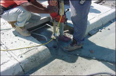
Figure 15. The diamond core bit was used to cut the steel bars found
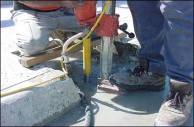
Figure 16. They used water to clean the holes and avoid over heating of the driller.
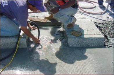
Figure 17. Workers cleaned the holes to eliminate any debris
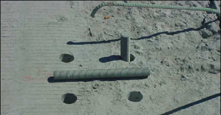
Figure 18 . The anchor bolts were placed in the holes already drilled
The bridge rail sections were placed in their final location (using the pilot holes as a guide). Construction grade epoxy was used to anchor the bolts into the bridge deck. The application of the epoxy was done with a funnel (see Figure 19). After the epoxy was poured, the anchor bolts were inserted in the pilot holes.
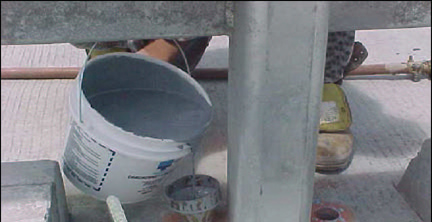
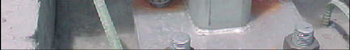
Figure 19. Epoxy Application
There was a little squeeze out of epoxy after inserting the bolts into the pilot holes (see Figure 20).
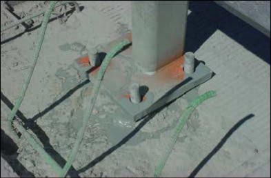
Figure 20. Epoxy Application
Unfortunately, some epoxy was splattered on the bridge rail. These stains were later cleaned up (see Figure 21).
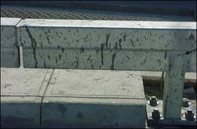
Figure 21. Bridge Rail section with epoxy stains. They were removed with an anti-abrasive liquid.
After the epoxy cured, washers and nuts were tightened, anchoring the bridge rail to the bridge deck (see Figures 22-24).
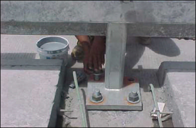
Figure 22. Placing of the washers and tightening of the nuts of the bridge rail sections
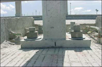
Figure 23. The nuts were tightened after the epoxy cured.
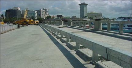
Figure 24. Partial assembly of the bridge rail sections
All the nuts were tightened after the epoxy application. Duct tape was placed at the free end of the anchor bolts (see Figure 25). The Contractor decided to do this to prevent future damage of the anchor bolts. This technique was used for future benefits, because if in the future the anchor bolts have to be removed, it will be easier to do it.
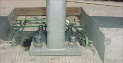
Figure 25. Duct tape application for prevent damage of the anchor bolts. The reinforced steel bars were left cut as shown.
4.7. Formwork Installation for the Re-construction of the Curbs and the Concrete Sidewalks
The formworks were installed after the tightening of the nuts to re-construct all the curbs that were demolished (see Figures 26-28). Also the open rectangular spaces, which were left for the bridge rail installation process, will be filled with concrete. Formworks were also installed at the other side of the concrete sidewalk (brick sidewalk side).
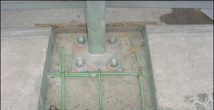
Figure 26. Formworks installation for the construction of the curbs and the concrete sidewalks
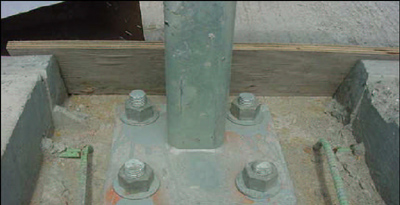
Figure 27. Formwork installation from the curb side
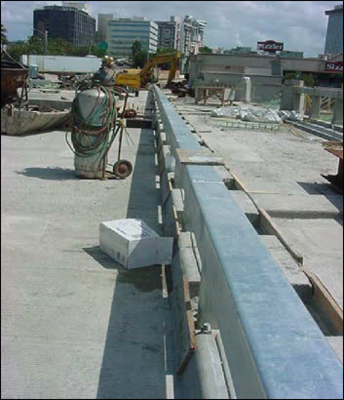
Figure 28. Complete installation of the formworks
4.8. Concrete placement for the Re-construction of the Curbs and the Concrete Sidewalks
After the formworks were placed, the concrete was poured to fill the open rectangular spaces that were left for the bridge rail installation process and to re-construct all the curbs that were demolished (see Figures 29-30).
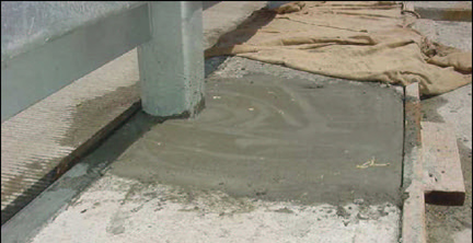
Figure 29. Type D concrete (5000 psi) concrete poured for the construction of the curbs and the concrete sidewalks
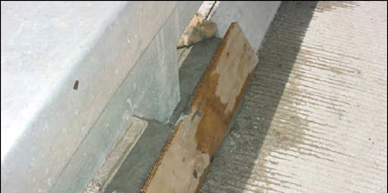
Figure 30. Concrete placement. Curb's side view
4.9. Curing of Concrete and Finished Curbs
The Contractor utilized moist burlap for curing the concrete. Water was added every two hours to the moist burlap to maintain its humidity and obtain a good curing of the concrete (see Figure 31).
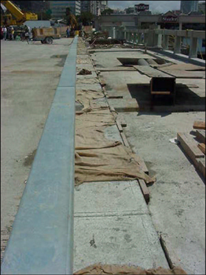
Figure 31. Moist burlap for curing the concrete
The curbs are finished (see Figures 32-33).
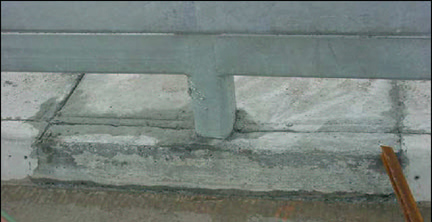
Figure 32: Front view of a finished curb
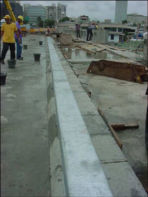
Figure 33: Finished concrete sidewalk and curb
4.10. Bridge Deck Expansion Joint
The bridge rail sections at the bridge deck expansion joint were adjusted. The bridge rail connection at this point coincided with the expansion joint. This connection was made with a separation of 2 in, the same separation at the expansion joint. Note that the joint sleeve was welded only to one section and free to move on the other section (see Figure 35).
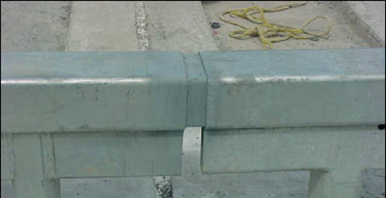
Figure 34. Bridge rail connection at the bridge deck expansion joint
4.11. Approach Slab and End Sections
The bridge rail sections at the approach slab and the rail end sections were constructed in the same way as the bridge rail at the deck (see Figures 35-38).
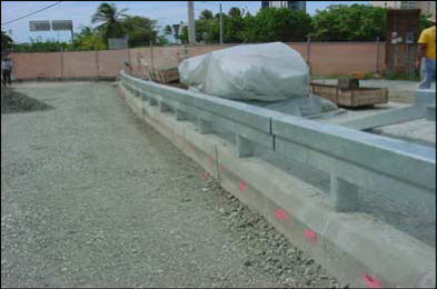
Figure 35. Sections corresponding to the approach slab
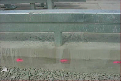
Figure 36. Finished curb and concrete sidewalks for the sections of the approach slab
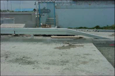
Figure 37. End section of the bridge rail system
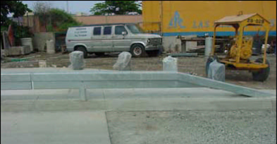
Figure 38 . End section of the bridge rail system
See Figures 39 and 40 for the complete view of the bridge rail finally installed as shown on the plans.
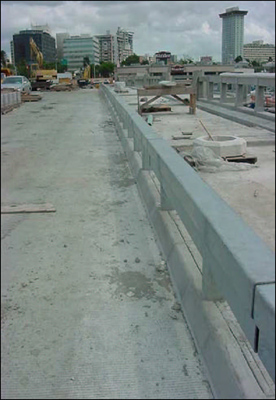
Figure 39. Final assembly of the bridge rail system
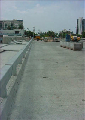
Figure 40. Final assembly of the bridge rail system
The following is a summary of the findings:
The following recommendations can be use as guidelines for future projects that include the installation of the Historic Bridge Rail System.

