Effects of Inlet Geometry on Hydraulic Performance of Box Culverts
CHAPTER 7. CONCLUSIONS AND RECOMMENDATIONS
Since most highway designers use HY-8 or a similar program for hydraulic design of culverts,highway agencies do not receive much benefit from research results until the results are finally coded into a computer program. Even the Corps of Engineers Hydrologic Engineering Center River Analysis System (HECRAS) program, used for most water surface profile studies, includes the HY-8 logic for culvert evaluations. The HY-8 program is currently being revised to incorporate recent research results and to allow for user-defined design coefficients.
As it is currently coded, HY-8 does not allow for user-defined design coefficients, which restricts practitioners from using research results until they are finally coded into a program. Since HY-8 and other similar programs are based on HDS-5, the best current approach for advancing the research to an implementation stage is to develop coefficients and performance curves in a format that is equivalent to the HDS-5 format, to derive fifth-order polynomials to facilitate coding inlet control performance curves in a computer program, and to identify which results will have the most impact on the applicability or clarity of HDS-5.
HDS-5 is the most widely recognized publication available on culvert hydraulics. All of the inlets tested in this study were inlets covered in HDS-5 with various combinations of entrance improvements. HDS-5 does not include thumbnail sketches of the inlet configurations that go with the descriptions, and it is sometimes difficult to visualize some of the details of the inlets. Nevertheless, experimental results in this study were compared to published coefficients in HDS-5 in cases where the inlets appeared to match the descriptions in HDS-5.
FINDINGS AND CONCLUSIONS
The major findings and conclusions of this study are:
- The discharge intensity is the primary independent variable used in culvert hydraulic analyses. As it is defined in HDS-5, the discharge intensity unnecessarily has units of ft1/2/s,, but it could just as easily be defined as a dimensionless Froude number by including the acceleration of gravity in the denominator. Almost all other parameters in culvert hydraulics are dimensionless and to make discharge intensity also dimensionless would greatly facilitate converting from one system to another in this period of dual units.
- The 20.32-cm- (8-inch-) radius top plate bevel was the optimum shape among six shapes tested. That radius is the full wall thickness of the top plate. The optimum top plate bevel does improve culvert performance significantly. The improvement is more pronounced for multiple barrels at higher headwater depths.
- The 45-degree straight top plate bevel, used for SDDOT field cast inlets, is an improvement over the square-edge top plate specified in HDS-5 for concrete box culverts with 0-degree wingwall flare angles.
- The precast models with 0-degree wingwall flare and optimum curved top plate bevels, as tested in these experiments, performed consistently better than the comparable field cast models with 0-degree wingwall flare and the traditional 45-degree top plate bevel. The precast models performed between the 0- and 30-degree flared wingwall field cast models, as illustrated in figures 83 and 84, except for multiple barrels at HW/D ratio greater than 1.5. At those ratios, the precast models actually performed better than the 30-degree-flared wingwall field cast model.
- The rounded bevels for wingwall top edges had no discernible effect on culvert performance.The square-edge models performed as well as the models with rounded bevels.
- The size of corner fillets had no discernible effect on the performance curves provided the net culvert area was used in the computation of the discharge intensity. The performance curves associated with various corner fillets in figures 46 and 47 can reasonably be combined as single curves, as illustrated in figure 85. The inlet control tests showed no difference for the various corner fillet sizes. There was a slight difference in the outlet control coefficient for the 30.48-cm (12-inch) corner fillets, but that difference can probably be attributed to experimental scatter.
- Multiple barrels had very little effect on performance curves for the field cast models. The double, triple, and quad curves in figures 50 and 51 can reasonably be combined as single curves, as illustrated in figures 86 and 87, and they could further be combined with the single barrel curves without much loss in accuracy. This observation gives credibility to the common practice of using single barrel design coefficients for multiple barrel culverts.
- Multiple barrels had more pronounced effect on performance curves for the precast models with the optimum top bevels, especially when the HW/D ratio was greater than 1.5, as illustrated in figure 88. This was an unexpected result, and several tests were rerun to confirm it. Most highway agencies, however, design culverts for headwater depth ratios below 1.5. Consequently, the practice of using single barrel coefficients is still reasonable.
- Span-to-rise ratios greater than 1:1 had very little effect on performance curves for either the field cast or the precast models, as illustrated in figures 89 to 91. Nevertheless, the error in using the 1:1 design coefficients for wider span culverts tends to be on the unconservative side, especially for inlets with flared wingwalls, as illustrated in figure 90.
- Extending the inner walls onto the approach apron for multiple barrel culverts had no discernible effect on performance curves. There is no hydraulic advantage (or disadvantage) from extending the inner walls.
- Skewed headwalls are unavoidable for some highway alignments, but they do have a detrimental effect on performance curves, as illustrated in figure 92. Results from this study do not agree with the limited guidance in HDS-5 for skewed headwalls.
- Exit flow from culvert models expanded at a gradual expansion angle of 5 to 6 degrees for a significant distance downstream from the culvert for both low and high tailwater depths.
- Entrance loss coefficients for low flows are important for fish passage considerations, but the unacceptable scatter, which can be attributed to instrumentation limitations for the very small losses that were associated with low flows, makes those results unreliable. Consequently,those coefficients for outlet control with free surface flow are not among the recommended results from this study. They are tabulated in an appendix for the benefit of other researcherswho may have similar difficulties.
- A commonly used prefabricated inlet for small circular culverts was highlighted from the literature review. Although it was not tested in this study, results were fairly consistent in two separate studies from the literature, and design coefficients from those studies are considered reliable.
Figure 83. Graph. PC and FC single barrel models (sketches 1, 7, 11 in figure 93).
Figure 84. Graph. PC and FC multiple barrel models (sketches 1, 2, 7, 8, 11, 12 in figure 93).
Figure 85. Graph. Combined corner fillet data, FC-S-0 and PC-A models (sketches 7, 10, 11, 14 in figure 93).
Figure 86. Graph. Combined multiple barrel data, FC-0 models (sketches 7, 8 in figure 93)
Figure 87. Graph. Combined multiple barrel data, FC-30 models (sketches 1, 2 in figure 93).
Figure 88. Graph. Combined multiple barrel data, PC models (sketches 11, 12 in figure 93).
Figure 89. Graph. Combined span-to-rise data, FC-S-0 models (sketches 7, 9 in figure 93).
Figure 90. Graph. Combined span-to-rise data, FC-S-30 models (sketches 1, 3 in figure 93).
Figure 91. Graph. Combined span-to-rise data, PC models (sketches 10, 13 in figure 93).
Figure 92. Graph. Skewed and nonskewed headwalls, FC-T-30 models (sketches 4, 5 in figure 93).
RECOMMENDATIONS
The following recommendations are for consideration by practitioners involved in field cast and precast culvert installations:
- Use the 20.32-cm- (8-inch-) radius top plate bevel for precast inlets where it is feasible to use more detailed forms.
- Continue the practice of using straight chamfer on the top edge of wingwalls because testing showed no benefit from rounding these edges.
- Base decisions to extend inner walls of multiple barrel culverts onto the apron on issues— such as debris control or aesthetics—other than hydraulics because testing showed no hydraulic advantage or disadvantage to extending these walls.
The following recommendations are for consideration as enhancements to future editions of hydraulic design manuals such as HDS-5 and future generations of hydraulic design software such as HY-8:
- Redefine discharge intensity as a dimensionless parameter, Q/A(gD)0.5, to facilitate conversion from one system of units to another. Keep the acceleration of gravity, g, in the independent parameter rather than embedding it in the design coefficients.
- Use thumbnail sketches, similar to those used in this report (figure 93), to clarify which inlet configurations correspond to design coefficients. Thumbnail sketches should also indicate the test conditions embankment slope if the applicable range of design coefficients might be affected.
- Define culvert area as net area rather than gross area when corner fillets are used. This should not affect current coefficients in HDS-5 because most historical testing was done without considering corner fillets.
- Expand the table of design coefficients to include box culverts with 30-degree-flared wingwalls and 45-degree straight beveled top plates, as described for sketch 1 in table 11.This expansion would reflect the performance of SD’s field cast culverts with flared wingwalls.
- Expand the table of design coefficients to include box culverts with 0-degree-flared wingwalls and 45-degree straight beveled and rounded top plates, as described for sketches 6 and 10 in table 11. This expansion would reflect the performance of SD field cast and precast culverts with straight-mitered inlets.
- Expand the table of design coefficients to include multiple barrel box culverts, as described for sketches 2, 8, and 12 in table 11. This expansion would document that multiple barrel culverts were tested and had very little effect on performance.
- Expand the table of design coefficients to include wide-span box culverts, as described for sketches 3, 9, and 13 in table 11. This expansion would document that, for flared wingwall installations, wide-span box culverts are slightly less effective than culverts with 1:1 span-torise ratios.
- Use the design coefficients in table 11 for inlets skewed to the flow direction due to skewed highway alignment relative to the flow direction. More research is needed to develop design coefficients for culvert barrels that are skewed to the flow direction. Although skewing culvert barrels to the flow direction is considered "bad practice," research is needed to show just how bad it is because the practice is not uncommon.
- Use table 12 for fifth-order polynomial coefficients that correspond to design coefficients in table 11. Fifth-order polynomials are coding expedients for computer software.
Table 11. Design coefficients suggested for future editions of HDS-5.
| Description | Source | Ke | K1 | M1 | K2 | M2 | c | Y |
|---|
Box, reinforced concrete |
30° to 75° flared wingwalls |
Chart 8/1, HDS-5 |
|
|
|
0.469 |
0.696 |
0.033 |
0.751 |
30° to 75° flared wingwalls, Square-edged crown |
Table 12, HDS-5 |
0.4 |
|
|
|
|
|
|
30° to 75° flared wingwalls, Crown edge rounded or top edge beveled |
Table 12, HDS-5 |
0.2 |
|
|
|
|
|
|
30° flared wingwalls, top edge beveled at 45° |
Single barrel |
Sketch 1, figure 93 |
0.26 |
0.005 |
1.05 |
0.44 |
0.74 |
0.04 |
0.48 |
2, 3, and 4 multiple barrels |
Sketch 2, figure 93 |
0.32 |
|
|
0.47 |
0.68 |
0.04 |
0.62 |
2:1 to 4:1 span-to-rise ratio |
Sketch 3, figure 93 |
0.20 |
|
|
0.48 |
0.65 |
0.041 |
0.57 |
15° skewed headwall, multiple barrels |
Sketch 4, figure 93 |
0.36 |
|
|
0.69 |
0.49 |
0.029 |
0.95 |
30° to 45° skewed headwall, multiple barrels |
Sketch 5, figure 93 |
0.45 |
|
|
0.69 |
0.49 |
0.027 |
1.02 |
0° flared wingwalls, extended sides |
Square-edged at crown |
Chart 8/3, HDS-5 |
0.7 |
|
|
0.55 |
0.64 |
0.05 |
0.55 |
Square-edged at crown |
Sketch 6, figure 93 |
0.79 |
0.055 |
0.68 |
0.55 |
0.64 |
0.047 |
0.55 |
45° straight bevel at crown, 0- and 6-inch corner fillets |
Sketch 7, figure 93 |
0.48 |
|
|
0.56 |
0.62 |
0.045 |
0.55 |
45° straight bevel at crown, 2, 3, and 4 multiple barrels |
Sketch 8, figure 93 |
0.52 |
|
|
0.55 |
0.59 |
0.038 |
0.69 |
45° straight bevel at crown, 2:1 to 4:1 span-to-rise ratio |
Sketch 9, figure 93 |
0.37 |
|
|
0.61 |
0.57 |
0.041 |
0.67 |
Crown rounded at 8-inch radius, 0- and 6-inch corner fillets |
Sketch 10, figure 93 |
0.24 |
|
|
0.56 |
0.62 |
0.038 |
0.67 |
Crown rounded at 8-inch radius, 12-inch corner fillets |
Sketch 11, figure 93 |
0.3 |
|
|
0.56 |
0.62 |
0.038 |
0.67 |
Crown rounded at 8-inch radius, 12-inch corner fillets, 2, 3, and 4 multiple barrels |
Sketch 12, figure 93 |
0.54 |
|
|
0.55 |
0.60 |
0.023 |
0.96 |
Crown rounded at 8-inch radius, no fillets, 2:1 to 4:1 span-to-rise ratio |
Sketch 13, figure 93 |
0.30 |
|
|
0.61 |
0.57 |
0.033 |
0.79 |
| Note: The source column refers to two documents: HDS-51 and figure 93 in this report. Empty cells mean no data are available. | 1 inch = 2.54 cm |
Table 12. Fifth-order polynomial coefficients.
| Description | Source | a | b | C | d | e | f |
Box, reinforced concrete |
30° to 75° flared wingwalls |
Chart 8/1, HDS−5 |
0.175897 |
0.20233 |
0.139818 |
−0.071970 |
0.014148 |
−0.000930 |
30° to 75° flared wingwalls, Square-edged crown |
Table 12, HDS−5 |
|
|
|
|
|
|
30° to 75° flared wingwalls, Crown edge rounded or top edge beveled |
Table 12, HDS−5 |
|
|
|
|
|
|
30° flared wingwalls, top edge beveled at 45° |
Single barrel |
Sketch 1, figure 93 |
0.163450 |
0.127103 |
0.256193 |
−0.131630 |
0.025211 |
−0.001600 |
2, 3, and 4 multiple barrels |
Sketch 2, figure 93 |
0.112542 |
0.375074 |
0.002657 |
−0.026380 |
0.006867 |
−0.000470 |
2:1 to 4:1 span-to-rise ratio |
Sketch 3, figure 93 |
0.182681 |
0.209471 |
0.158774 |
−0.092970 |
0.019381 |
−0.001310 |
15° skewed headwall, multiple barrels |
Sketch 4, figure 93 |
0.182031 |
0.686256 |
−0.277040 |
0.082113 |
−0.01167 |
0.000654 |
30° to 45° skewed headwall, multiple barrels |
Sketch 5, figure 93 |
0.363958 |
0.283523 |
0.069040 |
−0.044221 |
0.008965 |
−0.000595 |
0° flared wingwalls, extended sides |
Square-edged at crown |
Chart 8/3, HDS−5 |
|
|
|
|
|
|
Square-edged at crown |
Sketch 6, figure 93 |
0.278122 |
−0.002930 |
0.448521 |
−0.228310 |
0.044973 |
−0.00299 |
45° straight bevel at crown, 0- and 6-inch corner fillets |
Sketch 7, figure 93 |
0.244295 |
0.129322 |
0.339620 |
−0.189660 |
0.038635 |
−0.0026 |
45° straight bevel at crown, 2, 3, and 4 multiple barrels |
Sketch 8, figure 93 |
0.164261 |
0.43842 |
−0.03128 |
−0.01919 |
0.006288 |
−0.00046 |
45° straight bevel at crown, 2:1 to 4:1 span-to-rise ratio |
Sketch 9, figure 93 |
0.254968 |
0.273934 |
0.154712 |
−0.09911 |
0.020506 |
−0.00135 |
Crown rounded at 8-inch radius, 0- and 6-inch corner fillets |
Sketch 10, figure 93 |
0.203424 |
0.31092 |
0.10783 |
−0.07609 |
0.015779 |
−0.00102 |
Crown rounded at 8-inch radius, 12-inch corner fillets |
Sketch 11, figure 93 |
0.203424 |
0.31092 |
0.10783 |
−0.07609 |
0.015779 |
−0.00102 |
Crown rounded at 8-inch radius, 12-inch corner fillets, 2, 3, and 4 multiple barrels |
Sketch 12, figure 93 |
0.10315 |
0.619895 |
−0.23147 |
0.071093 |
−0.01075 |
0.000628 |
Crown rounded at 8-inch radius, no fillets, 2:1 to 4:1 span-to-rise ratio |
Sketch 13, figure 93 |
0.199715 |
0.446748 |
−0.02414 |
−0.02334 |
0.006761 |
−0.00048 |
| Note: The source column refers to two documents: HDS-51 and figure 93 in this report. Empty cells mean no data are available. | 1 inch = 2.54 cm |
Figure 93. Thumbnail sketches of inlets recommended for implementation.
a. Sketch 1
30°-flared wingwalls; top edge beveled at 45° |  |
b. Sketch 2
30°-flared wingwalls; top edge beveled at 45°; 2, 3, and 4 multiple barrels | 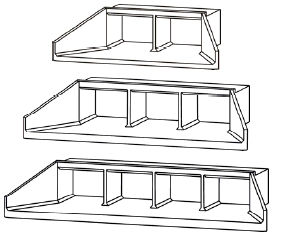 |
c. Sketch 3
30°-flared wingwalls; top edge beveled at 45°; 2:1 to 4:1 span-to-rise ratio | 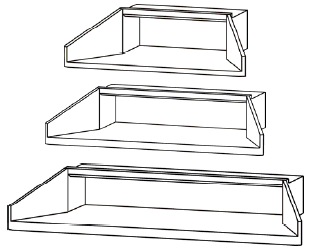 |
d. Sketch 4
30°-flared wingwalls; top edge beveled at 45°; 15° skewed headwall with multiple barrels |  |
e. Sketch 5
30°-flared wingwalls; top edge beveled at 45°; 30° to 45° skewed headwall with multiple barrels | 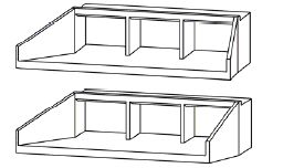 |
f. Sketch 6
0°-flared wingwalls (extended sides); square-edged at crown |  |
g. Sketch 7
0°-flared wingwalls (extended sides); top edge beveled at 45°; 0- and 6-inch corner fillets |  |
h. Sketch 8
0°-flared wingwalls (extended sides); top edge beveled at 45°; 2, 3, and 4 multiple barrels | 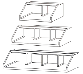 |
i. Sketch 9
0°-flared wingwalls (extended sides); top edge beveled at 45°; 2:1 to 4:1 span-to-rise ratio | 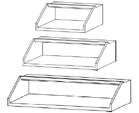 |
j. Sketch 10
0°-flared wingwalls (extended sides); Crown rounded at 8-inch radius; 0- and 6-inch corner fillets |  |
k. Sketch 11
0°-flared wingwalls (extended sides); Crown rounded at 8-inch radius; 12-inch corner fillets |  |
l. Sketch 12
0°-flared wingwalls (extended sides); Crown rounded at 8-inch radius; 12-inch corner fillets; 2,3, and 4 multiple barrels | 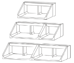 |
m. Sketch 13
0° -flared wingwalls (extended sides); Crown rounded at 8-inch radius; 12-inch corner fillets; 2:1 to 4:1 span-to-rise ratio. | 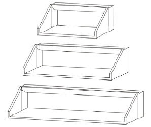 |
n. Sketch 14
0°-flared wingwalls (extended sides); top edge beveled at 45°; 12-inch corner fillets |  |
| Note: Extended center walls do not affect flow conditions. | 1 inch = 2.54 cm |
Previous | Contents | Next
|
