U.S. Department of Transportation
Federal Highway Administration
1200 New Jersey Avenue, SE
Washington, DC 20590
202-366-4000
Federal Highway Administration Research and Technology
Coordinating, Developing, and Delivering Highway Transportation Innovations
 |
| This report is an archived publication and may contain dated technical, contact, and link information |
|
Publication Number: FHWA-RD-99-156 Date: August 2004 |
Enhanced Abutment Scour Studies for Compound ChannelsCHAPTER 4. ANALYSIS OF RESULTSEQUILIBRIUM SCOUR DEPTHClear-water scour at a bridge abutment located on the floodplain of a compound open channel is influenced by the flow distribution between the floodplain and the main channel in the approach and contracted bridge cross sections. It has been shown that the effect of the flow contraction can be accounted for by the discharge contraction ratio M, which depends on both the abutment length and the discharge distribution in the approach section of a compound channel.(20) In addition, previous equations for predicting clear-water scour depths at abutments have depended on the ratio of floodplain velocity V1 to critical velocity Vc in the bridge approach section,(14,20) with maximum clear-water scour occurring when V1 approaches Vc (see chapter 2). In this formulation, the independent variables for scour prediction are determined from one-dimensional numerical models such as WSPRO. Sturm and Chrisochoides(86) have explored the suitability of these one-dimensional estimates of reference velocities and depths for scour prediction, and their results will be given in this chapter. For the case of significant backwater caused by the bridge opening, Sturm and Sadiq(23) have shown that the appropriate reference depth is the unconstricted floodplain depth rather than the approach floodplain depth with the bridge constriction in place. Extension of this methodology to abutments that encroach on the banks of the main channel in a compound channel has been reported by Sturm and Chrisochoides(87) and will be discussed in this chapter along with a consideration of the live-bed scour case. A possible alternative to parameterizing scour depth in terms of approach velocity and discharge distribution is to relate it directly to local hydraulic conditions near the abutment face, although these conditions can only be predicted by two- or three-dimensional numerical models. Possible advantages of this alternative formulation include: (1) it may provide a means of unifying scour-prediction equations obtained from experiments in rectangular channels with those based on the more realistic compound-channel geometry, and (2) it may offer greater sensitivity of scour predictions to changes in local depth and velocity at the location of scour initiation near the abutment face. Theoretically, local scour is initiated when the ratio of local flow velocity to critical velocity exceeds unity, and it continues at an ever-decreasing rate until equilibrium is reached. The initial rate of scour and limiting equilibrium depth of scour might be expected to depend on the excess of the local velocity ratio in comparison to unity among other variables. The implementation procedure for the prediction of clear-water abutment scour that is described herein is based on laboratory experiments in two different compound-channel cross sections as described in chapter 3. Abutment length, abutment shape, discharge, and sediment size were varied, and the resulting equilibrium scour depths were measured. In this chapter, a relationship for the prediction of equilibrium scour depth is formulated. CLEAR-WATER SCOUR: FORMULATION IThe first formulation is based on Laursen's long contraction scour theory for clear-water scour(13) as modified by Sturm and Sadiq(23) for abutments ending on the floodplain of a compound channel (setback abutments). The long contraction theory is also extended to the case of the abutment encroaching on the bank of the main channel (bankline abutments) for both clear-water and live-bed scour. The theoretical development for clear-water scour is given first, followed by correlation of the scour data for both compound channels A and B. Theoretical Clear-Water Contraction Scour for Setback Abutments With reference to figure 23 for equilibrium scour conditions in a long contraction, it is assumed that the approach conditions tend toward the unconstricted depth and velocity on the floodplain, yf0 and Vf0, respectively. This assumption is consistent with the assumption of an idealized contraction with negligible head loss and velocity-head changes made by Laursen(13) in his analysis of clear-water contraction scour. The continuity equation for the floodplains from the approach section to the contracted section at equilibrium is:
where Vf0 and yf0 = average unconstricted velocity and depth in the approach floodplain, respectively; Vf2 and yf2 = average velocity and depth in the contracted floodplain, respectively; and µf = generalized discharge contraction ratio. If the channel is rectangular with a width equal to the floodplain width, then µf = Bf2/Bf0, the ratio of contracted floodplain width to approach floodplain width. However, in a compound channel, some of the approach floodplain flow joins the main-channel flow in the contracted section as shown previously in figure 7(b). Under these circumstances, µf becomes an empirical factor that depends on the flow distribution in the approach channel and its redistribution between the main channel and the floodplain in the contracted section. For equilibrium clear-water scour conditions, the velocity in the contracted floodplain section, Vf2, is set equal to the critical velocity, Vf2c. If this substitution is made in equation 24, and it is divided by the critical velocity in the approach section, Vf0c, the result is:
Now from equation 23 for critical velocity, the ratio of critical velocities, Vf2c/Vf0c, is proportional to the ratio of the corresponding depths to the 1/6 power (i.e., (yf2/yf0)1/6). If this substitution is made in equation 25 and it is solved for yf2/yf0, the resulting equation is:
An equation of this form has been suggested by Richardson and Davis(8) in HEC-18 for estimating clear-water contraction scour, except that µf is evaluated as a geometric contraction ratio. Using the assumption that velocity-head changes and head losses at equilibrium contraction scour are small,(13) it can be shown that yf2 = dsc + yf0 (see figure 23). Then equation 26 can be written in terms of the theoretical contraction scour depth, dsc, as:  Figure 23. Definition sketch for idealized floodplain contraction scour in a laboratory compound channel, compound channel A.
Laursen's(13) assumption is that local abutment scour ds = rdsc, where r is some constant greater than 1 that multiplies the theoretical contraction scour depth given by equation 27. Although the contraction scour predicted by equation 27 is for a fictitious long contraction with several restrictive assumptions, including the assumption that the approach depth and velocity tend toward their unconstricted values as scour approaches equilibrium, it suggests that an equation for abutment scour might take the form:
where Cr and C0 are constants to be determined by experiment, and the exponent in equation 27 has been taken to be approximately unity as found in several experimental investigations.(14,19) There are two dimensionless ratios of interest on the right-hand side of equation 28. The velocity ratio in the numerator is the unconstricted floodplain velocity in the approach section in ratio to the critical velocity under the same conditions. Theoretically, once this velocity ratio reaches the value of unity, maximum clear-water scour occurs and live-bed scour begins, assuming that the approach depth and velocity tend toward their unconstricted values as equilibrium is reached. The other independent dimensionless variable in equation 28, which is especially relevant in the present experiments, is the discharge contraction ratio at equilibrium, µf. Sturm and Janjua(20) suggested the use of the discharge contraction ratio M, which is defined as the ratio of unobstructed discharge in the approach channel to total discharge at the beginning of scour, as an estimate of µf. They showed that M was a good estimate of µf for small depth changes in the contraction, which was indeed the case for their experiments with a contraction experiencing negligible changes in depth through the contraction because the tailwater was high with respect to critical depth. However, if there is choking in the contraction and/or significant upstream backwater at the beginning of scour, then an improved estimate of µf is needed. If it is assumed that M is an estimate of qf1/qf2 as shown by Sturm and Janjua,(20) then µf can be estimated as:
where M is evaluated for the approach depth at the beginning of scour and can be obtained from the WSPRO output,(21) qf0 = Vf0yf0 at the end of scour as estimated by the unconstricted approach floodplain velocity and depth, and qf1 = Vf1yf1 at the beginning of scour determined by the approach floodplain velocity and depth obtained from the constricted water-surface profile in the WSPRO output. Substituting equation 29 into equation 28 results in:
Theoretical Clear-Water Contraction Scour for Bankline Abutments For the abutment encroaching on the main-channel banks, the floodplain portion of the contracted section no longer exists, and the formulation of equation 30 has to be revised for this case. As shown in figure 24, the idealized contraction scour is assumed to occur in the contracted main-channel section, and by definition for La = Bf, M is exactly equal to qm1/qm2 for a constant-width main channel. Thus, in the contracted section, continuity for critical conditions at equilibrium scour results in:
where Vm2c = critical velocity in the main channel at the contracted section at equilibrium, ym2 = depth of flow in the contracted section in the main channel for equilibrium scour, qm1 = flow rate per unit width in the approach main-channel section at the beginning of scour, and M = discharge contraction ratio. Dividing equation 31 by Vm0cym0 gives:
where Vm0c = the critical velocity in the main channel for the unconstricted flow depth in the main channel of ym0. Using equation 23 to replace the ratio of critical velocities on the left side of equation 32 with the ratio of depths to the 1/6 power, (ym2/ym0)1/6, and solving for ym2/ym0 produces:
To be consistent with the case of the abutment terminating on the floodplain, it seems convenient to define the depth of scour relative to the floodplain elevation in both cases. Then, as  Figure 24. Definition sketch for idealized main-channel contraction scour in a laboratory compound channel, compound channel B. shown in figure 24, ym2 = dsc + yf0. Again, for consistency with equation 30, equation 33 can be multiplied by ym0/yf0 to yield:
Finally, if it is assumed that the 6/7 power can be approximated by unity as in the previous floodplain scour analysis, equation 34 can be placed in a form similar to equation 30:
where the coefficients Cr' and C0', in general, would not be the same for floodplain scour as given by equation 30. Correlation of Results The correlation of scour-depth measurements according to equation 30 is presented in figure 25 for the shorter abutment lengths with significant setbacks from the bank of the main channel (setback abutments). The results for vertical-wall abutments are given for both compound channels (A and B) and for relative abutment lengths La/Bf varying from 0.17 to 0.66. Sediment sizes of 1.1 mm, 2.7 mm, and 3.3 mm are included in the results in figure 25. Shown for comparison in figure 25 is the proposed relationship suggested by Sturm and Janjua(20) from a much more limited data set in a short, horizontal laboratory compound channel. In the latter data set, the tailwater essentially submerged the contraction so that there was very little backwater from the contraction; however, these data agree with the present data if the unconstricted floodplain depth is substituted for yf0, even though it is not the normal depth. The best-fit relationship for all of the data is also given in the figure for which Cr = 8.14 and C0 = 0.40 in equation 30. For this relationship, the coefficient of determination r2 is 0.86, and the standard error of estimate in ds/yf0 is 0.68. In figure 26, the scour data for longer abutments that approach the bank of the main channel (bankline abutments) are correlated according to equation 35. These additional data comprise relative abutment lengths La/Bf of 0.88, 0.97, and 1.0. The major differences between equations 30 and 35 are the replacement of qf1 in equation 30 with qm1 in equation 35, and the evaluation of the critical velocity in the main channel for the unconstricted depth ym0 in equation 35 instead of the critical velocity in the floodplain in equation 30. The value qm1 was evaluated approximately as the measured discharge in the approach main channel divided by the main-channel topwidth. For those cases in which the tailwater depth exceeded normal flow depth, the tailwater depth yftw was substituted for the normal depth yf0. It can be observed from figures 11 and 12 that the tailwater depth is representative of the depth in the contracted section as was the normal depth  Figure 25. Scour-depth relationship based on approach hydraulic variables for VW abutments with 0.17  Figure 26. Scour-depth relationship based on approach hydraulic variables in main channel for VW and ST abutments with 0.88 for the unsubmerged cases. Strictly speaking, the derivation of equation 35 applies only to the case of La/Bf = 1.0; however, the additional abutment length data seem to follow the same trend in figure 26. The scour hole clearly extends from the floodplain into the main channel for La/Bf = 0.88 in figures 18(a) and 20(a), while it is localized near the abutment face on the floodplain in figure 19(c). In all cases of La/Bf = 0.97 and 1.0 in figures 18, 19, and 20, the scour hole is located in the main channel. The best-fit values of the coefficients in equation 35 are Cr' = 2.0 and C0' = 0.47, with an r2 = 0.92 and a maximum value of ds/yf0 of approximately 10. The data shown in figure 26 represent the maximum total scour depths regardless of their classification as local or contraction scour. Indeed, these two types of scour occur simultaneously at different locations, as in figure 18(b), while interfering and combining as in figure 18(c), for example. Furthermore, the lengthening of the scour hole in the upstream direction in figures 20(b) and 20(c) seems to reflect the interaction of the floodplain and main-channel flows well upstream of the abutment in a contraction-scour effect. Based on these results, the artificial addition of contraction and local abutment scour when the abutment is near the bank of the main channel may be responsible for the overestimates of scour in these cases. If the scour is a combined local and contraction effect for abutments near the bank of the main channel, it would seem that either equation 30 or 35 might serve as scour predictors because both are based on acceleration of the flow caused by the contraction (i.e., the floodplain flow in the case of equation 30 and the main-channel flow in the case of equation 35). Accordingly, the data for both short and long abutments are combined in figure 27, with the critical velocity calculated in the main channel for La/Bf = 0.97 and 1.0, and in the floodplain for all other cases. In other words, equation 30 is modified as:
where Vxc = Vf0c for abutments located on the floodplain (setback abutments), and Vxc = Vm0c for abutments near the bank of the main channel (bankline abutments). In addition, the data for spill-through and wingwall abutments are incorporated into figure 27. It is apparent that the relative scour depth levels off to a constant value for large values of the independent variable just as in figure 26. The actual mean value of the relative scour depth is 9.4 ± 1.0 after the point of leveling off; however, considering the uncertainty involved and remaining on the conservative side, the maximum value is shown as 10 in figure 27. The scour data for the linear portion of the graph are compared with the best-fit relationship given previously in figure 25 for the setback abutments only. The data for compound channel A are not shown in the figure to retain clarity; nevertheless, the best-fit regression analysis remains essentially unchanged with the addition of the long abutment data (Cr = 8.14, C0 = 0.40), except that the standard error of estimate for the relative scour depth increases from 0.68 to 0.75. In all cases, the scour depth is defined as the maximum depth in the scour hole measured below the undisturbed floodplain elevation. The fact that equations 30 and 35 both predict the scour depth reasonably well for the long abutments seems to be indicative of the contraction process controlling scour, whether it is measured by the main-channel flow acceleration or the floodplain flow acceleration. Both equations 30 and 35 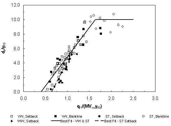 Figure 27. Scour-depth relationship based on approach hydraulic variables in floodplain for all abutments and sediments, compound channel B require an estimate of average floodplain depth in natural channels, and it is recommended that the average depth of flow blocked by the abutment and embankment on the floodplain in the approach section be used for the unconstricted flow (yf0) and the constricted flow (yf1) for consistency. Also shown in figure 27 are data for the spill-through and wingwall abutments. The spill-through data appear in two different regions, depending on the magnitude of the independent variable in figure 27. For shorter abutments, or more precisely, abutments that block less floodplain flow, the scour depth is smaller for the spill-through than for the vertical-wall abutment. The difference becomes less and less as the independent variable increases, which corresponds to an increasing discharge or an abutment that blocks more flow. The spill-through data seem to merge with the vertical-wall data for qf1/(MVxcyf0) greater than about 1.2 and remain comingled with the vertical-wall data as the best-fit line levels off at a maximum value of relative scour depth of about 10. Apparently, the local flow effects at the face of the abutment caused by the differences in the abutment shape become unimportant as the degree of contraction becomes large. A scour-depth correction for the spill-through shape can be derived from the data in figure 27. A least-squares best fit for the spill-through data produces a linear relationship, as shown in figure 27, having a coefficient of determination of r2 = 0.93, with a standard error of estimate for ds/yf0 of 0.45. If the relative scour depth for a spill-through abutment is taken as a ratio to the value for a vertical-wall abutment, the result is a shape correction factor for the spill-through abutment KST:
where Because of the influence of the discharge contraction ratio M and the backwater effects, it should not be assumed that the maximum clear-water scour depth of 10 times the unconstricted floodplain depth as shown in figure 27 is always the appropriate estimate of equilibrium scour depth. In other words, the scour depth can be less than 10 times the unconstricted floodplain flow depth measured below the floodplain even though the approach velocity has reached critical velocity and the threshold of live-bed scour. For example, as the abutment length decreases and less flow is blocked, M increases and approaches 1. In addition, backwater effects become less likely so that yf1 approaches yf0. So even if Vf1 = Vc, equation 29 gives a maximum relative scour depth ds/yf0 of approximately 5. Considered from a different viewpoint, large main channels with very rough floodplains tend to have larger values of M, which reduce the relative scour depth even if threshold live-bed conditions are reached in the approach channel. In addition, for increasing tailwater depths at the same discharge and abutment length, or for increasing the abutment length at the same discharge, the approach floodplain velocity is reduced, making threshold live-bed scour conditions much less likely to occur. In conclusion, it should not be assumed from figure 27 that a scour depth of 10 times the unconstricted floodplain depth is always the maximum equilibrium scour depth expected. CLEAR-WATER SCOUR: FORMULATION IIClear-water scour at a bridge abutment located on the floodplain of a compound open channel occurs at an ever-decreasing rate from the initiation of scour until equilibrium is achieved. Theoretically, local scour is initiated when the ratio of the local bed shear velocity U* to its critical value U*c, or the ratio of local flow velocity V to critical velocity Vc, exceeds unity. Furthermore, the initial rate of scour and limiting depth of scour have been shown to increase with the value of V/U*c in experiments on scour by jets of water.(79) Thus, although the local depth-averaged velocity near the abutment face is continually decreasing as the scour hole grows larger with time, it seems possible to relate the maximum depth of scour to the maximum depth-averaged velocity near the abutment face Vab at the beginning of scour as defined in figure 23. This velocity cannot be predicted by one-dimensional models. Biglari and Sturm(55) have applied a depth-averaged k- Dimensional Analysis As a test of the hypothesis that scour depends on the local depth-averaged velocity near the abutment face, a relationship for the equilibrium clear-water scour depth is sought in the form:
where ds = equilibrium scour depth, yf0 = unconstricted flow depth in the floodplain set by the uniform flow downstream of the bridge, yab = floodplain flow depth at the location of Vab in the contracted section, Vab = maximum velocity near the upstream corner of the abutment face,
where Fab = Vab/(gyab)0.5 = Froude number in the contracted floodplain near the abutment face, and Ns = Vab/[(SG - 1)gd50]0.5 = sediment number in the contracted section as defined by Carstens,(80) with SG = specific gravity of the sediment. The value of the relative roughness (d50/yab) can be replaced by the critical value of the Froude number Fc, or the critical value of the sediment number Nsc, for the case of fully rough turbulent flow(85) as in these experiments. For quartz sediment and water, either Fab or Ns can be considered redundant with respect to the other. If it is further assumed that scour is related to the excess of velocity (or sediment number) with respect to its critical value as suggested by several sediment transport formulas,(80, 90-92) a relationship for dimensionless scour can be presented as:
Alternatively, the scour relationship could be given as:
Correlation of Results Figure 28 illustrates the correlation of scour data in terms of the excess velocity ratio suggested by equation 41. The experimental scour data for compound channel A were measured by Sadiq(22) and reported by Sturm and Sadiq,(23) while the scour data for compound channel B were collected as part of this study. The values of Vab and yab were predicted by Biglari's numerical two-dimensional turbulence model for compound channel A,(54) while they were measured for compound channel B. For compound channel A, the left and right floodplains were slightly asymmetrical because of finite construction tolerances so that slightly different scour depths were measured for the left and right abutments. These two scour depths in each experiment were averaged for comparison with the numerical model runs, which assumed perfect symmetry. The value of Vc was calculated from Keulegan's equation as a function of d50/yab, with the appropriate values of Shields' parameter. The results in figure 28 include experimental data for compound channels A and B for six different values of La/Bf up to a maximum of 0.66, and for three different sediment sizes (1.13 to 3.30 mm). The value of La/yf0 varied from 3 to 90, which includes both intermediate- and large-scale abutment lengths according to Melville's classification.(14) The variable yab/yf0 in equation 41 is an indication of relative local water-surface drawdown near the upstream corner of the abutment; however, it was found not to be a significant explanatory variable for the observed scour depths in these experiments. The coefficient of determination for the least-squares best-fit relationship in figure 28 is r2 = 0.88, and the best-fit equation is: 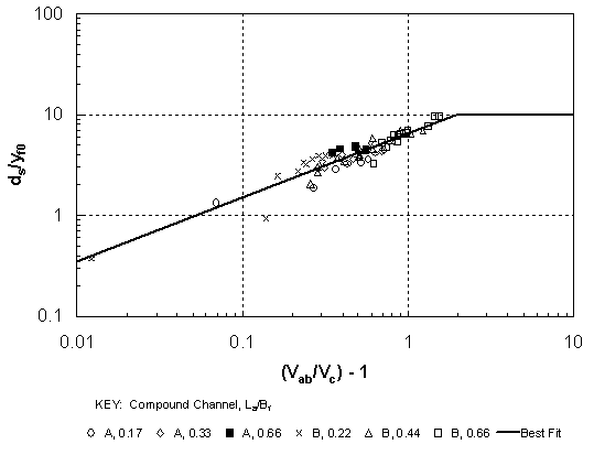 Figure 28. Scour-depth relationship based on local hydraulic variables for VW abutments with La/Bf
for [(Vab/Vc) - 1] If the data for longer abutments are also plotted according to equation 42, it can be observed in figure 29 that the best-fit relationship does not compare well with these data. It is plausible that the measurement of Vab as a depth-averaged, resultant velocity is no longer sufficient to explain the complex, three-dimensional flow pattern that occurs at the face of the abutment as the abutment encroaches on the main channel. Clearly, an additional flow factor is needed to explain better the scour data for this case, barring the use of a three-dimensional numerical model. DISCUSSIONA comparison of figures 25 and 28 shows relatively little difference in using formulations I or II for scour prediction for relative abutment lengths less than 0.66. Formulation I is based on variables easily determined by WSPRO, while formulation II requires output from at least a two-dimensional, depth-averaged numerical model. It is not clear that the finite elements surface water modeling system (FESWMS) will satisfy this need with its assumption of constant eddy viscosity. Biglari's model(54-55) used a k- There is ample precedent for taking the "hydraulic approach" and developing a simple method for predicting Vab along with a velocity adjustment factor for longer abutments until more advanced numerical models are readily available and usable. For example, one possible reference velocity is the mean cross-sectional velocity in the contracted cross section that can be obtained from WSPRO. However, relating Vab to the average cross-sectional velocity for the whole cross section is complicated by the fact that WSPRO predicts the average cross-sectional velocity at the downstream face of the bridge, whereas Vab is the resultant, depth-averaged velocity at the upstream corner of the abutment face. In addition, the average cross-sectional velocity is not at all representative of the floodplain velocity for setback abutments that are located on the 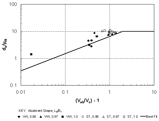 Figure 29. Scour-depth relationship based on local hydraulic variables for VW and ST abutments with La/Bf floodplain. The floodplain velocity in the contracted section is, in reality, determined by both the local acceleration near the abutment face and the entrainment of the floodplain flow into the main channel. Furthermore, the practice of taking the WSPRO streamtube velocity nearest the abutment face in the floodplain is bound to fail (as will be shown subsequently) because the flow distribution in WSPRO is determined by the conveyance distribution, which does not reflect the flow acceleration around the abutment face. As the abutment encroaches on the main channel, the entrainment of the floodplain flow into the main-channel flow occurs near the abutment face so that again a simple estimate of mean cross-sectional velocity cannot properly predict the scour potential in this highly three-dimensional flow region. In spite of these difficulties, there remains one other possibility suggested by the fact that the independent dimensionless variables in figures 25 and 28 provide a similar degree of explanation of scour depth so that they must be related to each other. The correlation between the two for the shorter abutments (La/Bf
Equation 43 has the advantage that it depends on hydraulic variables on the right-hand side that can be predicted well by a one-dimensional model such as WSPRO. However, the data for longer abutments (La/Bf APPLICATION TO LIVE-BED CONDITIONSLive-bed scour is the condition in which sediment transport occurs in the channel approaching the bridge contraction so that sediment continuously passes through the scour hole. Equilibrium is reached when the sediment transport rate out of the scour hole equals the sediment transport rate into the scour hole. For a compound channel in riverbank flow, the floodplain velocities are quite likely to be less than the critical velocity so that live-bed conditions can be realized only in the main channel. Thus, as a practical matter, abutment scour under live-bed conditions is often limited to the case of the abutment's encroaching on the bank of the main channel with sediment transport occurring only in the approach main channel. Even this condition may be difficult to find in practice if there is significant upstream backwater, which leads to a rise in stage and a reduction in approach velocity below the value required to carry sediment. The live-bed scour analysis is based initially on contraction scour. The basic condition that must be satisfied for equilibrium live-bed scour comes from a continuity of sediment transport rates between the approach main channel and the main channel in the contracted section, which may, in general, have different widths. If we use the Meyer-Peter and Mueller bedload function,(75) for example, then it must be true that:
where subscripts 1 and 2 refer to the approach and contracted main channel, respectively, and q*bv is the dimensionless volumetric sediment transport rate given as:
where qbv = volumetric sediment transport rate per unit width, SG = specific gravity of the sediment, d50 = median sediment grain size,
Note that for Bm2 = Bm1, Now Shields' parameter can be expressed in terms of the shear stress formula and Manning's equation for uniform flow in a wide channel in SI units as:
Then, taking the ratio of Shields' parameter between the approach and contracted sections, and replacing the velocity, V, with Q, using continuity for a rectangular main channel, the result is:
where it has been assumed that Manning's n remains constant from the approach to the contracted section in the main channel. Solving for the depth ratio, we have:
Now, equations 46 and 49 can be solved simultaneously for the scour depth ym2 relative to the water surface. The solution is shown graphically in figure 31 in the form of a live-bed scour coefficient, CLB, defined as:
where
From equation 51 and figure 31, it is apparent that the coefficient CLB depends on the ratio of approach shear stress to critical shear stress in the main-channel It is useful at this point to compare the theoretical clear-water contraction scour given by equation 33 and the live-bed contraction scour given by equations 50 and 51. Both equations are for bankline abutments for which the abutment is at the edge of the main channel (La = Bf). In the limiting case where there is no backwater (ym0 = ym1) and the approach and contracted main-channel sections have equal widths (Bm1 = Bm2), the threshold live-bed scour occurs for Vm1 = Vm0c in equation 33. Under these conditions, equation 33 becomes:
Upon comparison with the live-bed scour equation given by equations 50 and 51, it is clear that equations 50-52 are identical for CLB = 1, which is true for Bm1 = Bm2 and from the definition of M = Qm1/Q. Furthermore, the live-bed scour coefficient remains equal to 1 as For live-bed scour in the main channel and Bm1 is not equal to Bm2, the data in this report are not directly applicable. However, it has been shown theoretically that live-bed and clear-water contraction scour equations are identical for Bm1 = Bm2 and CLB = 1.0 at the threshold of live-bed scour. Furthermore, the experimental data taken in this study resulted in equation 35, which predicts a combined abutment and contraction scour of approximately twice (Cr' = 2) the theoretical contraction scour for the abutment at or near the bank of the main channel. This suggests that an equation like equation 35 could be combined with the theoretical live-bed coefficient of equation 51 to predict total contraction and abutment live-bed scour for bankline abutments even if Bm1 is not equal to Bm2. Further experiments are needed to confirm this hypothesis. This theoretical analysis does not account for the observation that a second live-bed scour peak different from the threshold live-bed scour peak ( WSPRO PREDICTIONSTo determine the adequacy of one-dimensional hydraulic computations to be used in formulation I scour predictions, WSPRO simulations of the water-surface profiles and approach velocity distributions for both compound channels A and B are compared to measured laboratory results in this section. Some comparisons are also made with the results from Biglari's two-dimensional numerical model. (54, 55) More extensive comparisons and discussion can be found in a previous report by the author(78) and in a paper by Sturm and Chrisochoides.(86) In the WSPRO runs for compound channel A, Manning's n was assumed to be constant with depth, with values of 0.020 for the main channel and 0.0174 for the floodplain based on the experimental data for uniform flow. Computed and measured water-surface profiles for compound channel A are compared in figure 32 for a discharge of 0.057 m3/s and for a vertical-wall abutment having a relative length of La/Bf = 0.33. The two-dimensional numerical model tracks the experimental results for depth very closely, both upstream and downstream of the abutment, including the expansion zone immediately downstream of the abutment where WSPRO merely produces a constant depth. This is clearly a limitation of the one-dimensional model. Of more interest, however, are the comparisons upstream of the abutment where WSPRO consistently overestimates floodplain depths by about 10 percent. Predicted velocity distributions in the bridge approach section are compared with measured values in figure 33 for the same experimental conditions as in figure 32. Both WSPRO and the two-dimensional numerical model predict approach floodplain velocities reasonably well. The two-dimensional model seems to capture well the velocity distribution in the interaction zone between the main channel and the floodplain, which was the reason for choosing a k- Comparisons between measured and computed velocity distributions in the bridge contraction section are shown in figure 34. In this section, WSPRO cannot predict the velocity distribution because of the accelerating nonuniform flow in the vicinity of the abutment face. The numerical model, however, shows computed resultant velocities at the upstream face of the bridge opening that agree well with the measured resultant velocities. Computed water-surface profiles for compound channel B are compared with measurements in figure 35 for a relative abutment length of La/Bf = 0.44 and a discharge of Q = 0.085 m3/s. In spite of the change in cross-sectional shape and channel roughnesses, the WSPRO comparisons are very similar to those for compound channel A. Downstream of the abutment, the WSPRO depth is nearly constant for uniform flow, while upstream of the abutment, the computed WSPRO depths are larger than the measured values, resulting in a relative error in floodplain depth of about 10 percent. In general, the computed WSPRO depths at the downstream face of 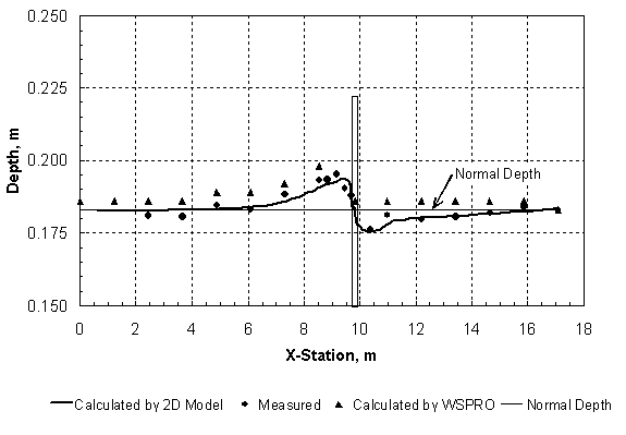 Figure 32. Calculated and measured water-surface profiles for compound channel A. (VW abutment, La/Bf = 0.33, Q = 0.057 m3/s).  Figure 33. Calculated and measured approach velocity distributions for compound channel A. (VW abutment, La/Bf = 0.33, Q = 0.057 m3/s). 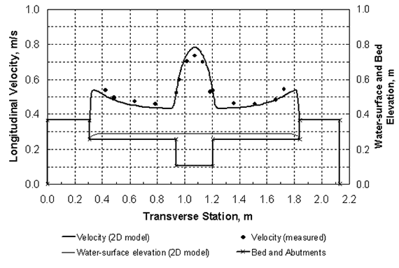 Figure 34. Calculated and measured resultant velocity distributions in the contracted section for compound channel A. (VW abutment, La/Bf = 0.33, Q = 0.057 m3/s). 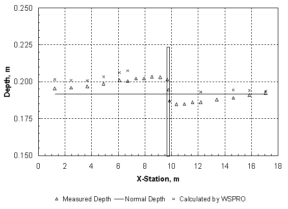 Figure 35. Calculated and measured water-surface profiles for compound channel B. (VW abutment, La/Bf = 0.44, Q = 0.085 m3/s). the bridge agree rather well with the measured values. Computed and measured approach velocity distributions for compound channel B are shown in figure 36 for the same experimental conditions as in figure 35. There is good agreement between measured and computed WSPRO velocities in the floodplain. However, computed velocities near the interface between the floodplain and the main channel are underpredicted by WSPRO because of the limitations of a one-dimensional model in this region. More detailed comparisons of computed and predicted values of Vf1, the approach floodplain velocity upstream of the end of the abutment; yf1, the approach floodplain depth; and M, the discharge distribution factor, are given in figures 37, 38, and 39 for both cross sections and all discharges with La/Bf In figure 39, computed and predicted values are shown for the discharge distribution factor M, which is defined as the ratio of the discharge, in that portion of the approach cross section having a width equal to the bridge opening width, to the total discharge. Thus, the prediction of M depends on the prediction of the approach depth and velocity distributions. It can be observed that M is predicted equally well by WSPRO and the two-dimensional numerical model in compound channel A; however, WSPRO underestimates M for the smaller values in compound channel B. This problem is caused by the differences in the velocity distributions noted earlier for compound channel B, as well as in the overprediction of yf1 by WSPRO. The results for M show that at least some of the effect of the main channel/floodplain interaction has been accounted for by using measured Manning's n values; however, this achieves only the correct split between the main-channel and floodplain flow, not necessarily the correct detailed velocity distribution near the interface. This is a problem with the one-dimensional analysis afforded by WSPRO that can be overcome by a two-dimensional numerical model. As a final comparison, the calculated and measured velocities in the bridge contraction section near the abutment face are shown in figure 40 for compound channel B. The measured velocities Vab are the measured maximum resultant velocities found near the abutment face. The velocities calculated by WSPRO for this case necessarily come from the bridge section at the downstream face of the bridge opening and are taken as the mean velocity in the streamtube nearest the abutment face. WSPRO clearly cannot predict velocities in this part of the accelerating flow field and would not be expected to do so. Based on these results, it is inadvisable to use WSPRO to predict velocities near the abutment face for use in scour-prediction equations. 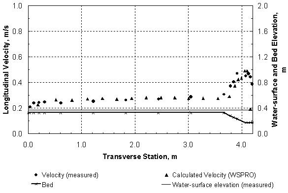 Figure 36. Calculated and measured approach velocity distributions for compound channel B. (VW abutment, La/Bf = 0.44, Q = 0.085 m3/s). TIME DEVELOPMENT RELATIONSHIPBased on the dimensional analysis result given by equation 45, time can be added as an independent variable in the scour development process to produce an expected relationship of the form:
where dst = scour depth at any time t. The influence of yab/yf0 has not been included in equation 48 based on the experimental results. The experimental measurements of scour depth with time are presented according to equation 53 for three sediment sizes (d50 = 3.3 mm, 2.7 mm and 1.1 mm) in figure 41. These results for the time development of scour include only those cases for which the maximum scour depth developed near the upstream corner of the abutment as discussed previously in chapter 3. However, the location of the scour hole at the upstream corner occurred for the larger discharges so that the worst cases are included in these results. The curves for different values of Vab/Vc have a functional form that begins with a linear development of scour depth with the logarithm of time, followed by an abrupt leveling off to a nearly constant value equal to the equilibrium scour depth that depends only on Vab/Vc. The functional behavior and collapse with respect to sediment size shown in figure 41 suggest the possibility of a universal set of time-development curves that can be applied to field cases provided that the dimensionless variables fall in the same range as in the laboratory experiments. Accordingly, a least-squares regression analysis was applied to the data and suggested interpolated curves were developed and plotted as solid lines in figure 41. Thus, for a given sediment size, which determines Vc; a given abutment velocity Vab, which is determined by the abutment shape, degree of floodplain contraction, and flow velocity distribution; and a given time corresponding to the design flood duration, an estimated depth of scour can be obtained. For example, if Vab/Vc = 1.5, approximately two-thirds of the equilibrium scour depth is reached in a flow duration of only about 10 percent of the equilibrium time. Figure 41 shows very clearly the interplay of time, flow distribution, and sediment size in determining a design value of abutment scour depth. COMPARISON OF SCOUR FORMULAS WITH MEASURED DATASeveral formulas for clear-water abutment scour depth, in addition to the one formulated herein, have been proposed in the literature. These were discussed in detail in chapter 2 and the formulas will be referred to as: (1) Melville,(14,24) (2) Froehlich clear-water scour (CWS),(12) (3) Froehlich live-bed scour (LBS),(12) (4) GKY,(66) and (5) Maryland.(68,70) The formulas proposed by Melville and Froehlich both include data collected in Auckland, New Zealand, in rectangular flumes. The GKY formula relies on data from Lim(67) and Sturm and Janjua,(20) while the Maryland procedure is based on experimental data in rectangular flumes assembled by Palaviccini.(69) Because the scour data collected in this study include both vertical-wall and spill-through abutments, a shape factor was applied for each formula. The shape factor for vertical-wall abutments was taken to be 1.0 for all formulas. The shape factor KST for spill-through abutments in the Melville formula varies linearly from 0.45 (for 1.5:1 sideslopes) to 1.0 as La/y1 varies from 10 to 25 and is constant outside of these limits with KST = 0.45 for La/y1 = 10 and KST = 1.0 for La/y1 = 25. (Melville does not give a shape factor for 2:1 sideslopes, so the closest value of 1.5:1 was used in the predictions to follow.) For the other formulas, a standard constant shape factor of 0.55 for spill-through abutments was used based on the guidance given by HEC-18. The formula from the present study (equation 36 with Cr = 8.14 and C0 = 0.40) is also compared with the experimental data using the shape factor for spill-through abutments derived herein as equation 37. The comparisons between the measured and predicted scour depths for the five formulas listed above are given in figures 42 through 46, for a total of 74 data points measured in the present study in a compound channel (compound channel B). The line of perfect agreement is shown as a solid line, and the two dashed lines indicate a variation of ±30 percent from the line of perfect agreement in order to gauge the degree of scatter in the comparisons. The Melville formula overpredicts scour depths in the lower range of the data by several hundred percent as shown in figure 42. Only about one-half of the data points fall within the ±30 percent range of variation relative to perfect agreement. The Froehlich CWS formula shown in figure 43 shows a similar pattern to the Melville formula, which is to be expected because they are based on a similar data set. However, several larger values of scour are underpredicted by the Froehlich CWS formula because of the constant spill-through abutment shape factor of 0.55, whereas the Melville formula has a shape factor of 1.0 for the larger values of La/yf1. The Froehlich LBS formula, which is recommended by HEC-18, even for clear-water scour, is given in figure 44. In general, it shows similar data scatter in comparison to the Froehlich CWS formula, but with greater overprediction of nearly all scour depths. The GKY and Maryland formulas in figures 45 and 46, respectively, display a trend opposite to that of the first three formulas. They both tend to underpredict the measured scour depth by considerably more than the lower 30-percent range. In order to maximize the predicted values for both formulas, the entire approach floodplain flow was assumed to pass through the contracted-section floodplain for La/Bf = 0.88, while the total flow was assumed to pass through the main channel in the contracted section for La/Bf = 0.97 and 1.0. In general, the Maryland formula predicts greater scour depths than the GKY formula, and both formulas suffer from the use of the spill-through shape factor of 0.55 when the present study as well as the experiments by Melville(24) show that it approaches 1.0 as the relative abutment length, or the fraction of blocked flow, becomes large. The GKY formula was applied in SI units with the leading constant factor of 1.37 as recommended in reference 66; however, a value approximately twice as large would greatly improve the performance of the formula. Finally, the formula recommended in this study is compared with the experimental data in figure 47. While the formula itself is based on the data used in the comparison, figure 47 is indicative of the overall performance of the formula. Only 6 of the 74 data points lie completely outside the ±30 percent range. Four of these outliers occur for measured scour depths on the order of 5 cm or less, which are more difficult to measure and reproduce because of the inherent uncertainty in the experiments. In conclusion, it seems that the formulas based primarily on experiments in rectangular flumes cannot reproduce the physics of the flow and the coupled flow distribution and scour behavior associated with the compound channel. 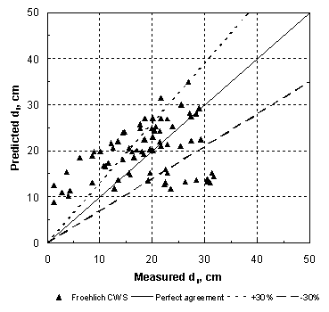 Figure 43. Comparison of measured and predicted scour depths using the Froehlich clear-water scour formula. 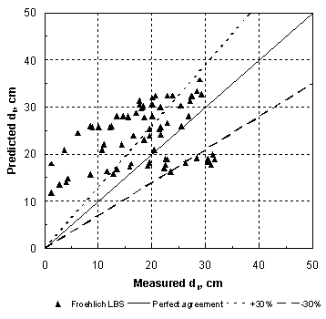 Figure 44. Comparison of measured and predicted scour depths using the Froehlich live-bed scour formula. 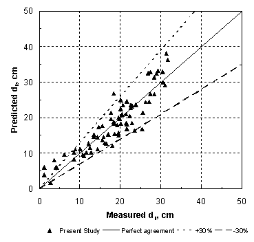 Figure 47 . Comparison of measured and predicted scour depths using the formula from the present study. PROPOSED IMPLEMENTATION PROCEDURE FOR ABUTMENT SCOUR PREDICTIONAs a result of the experimental results on the equilibrium depth of clear-water abutment scour given in figure 27 and on the time development of scour shown in figure 41, a prediction procedure that accounts for discharge distribution, sediment size, and time can be developed. Based on the extensive comparisons between WSPRO estimations of scour parameters and parameter estimation by a two-dimensional numerical turbulence model, it is assumed that the WSPRO predictions provide a reasonable estimation of the approach-flow hydraulic parameters for the prediction of clear-water abutment scour. It is further assumed that the abutment velocities to be used in the scour time development determination in figure 41 can be obtained from the relationship developed in figure 30, which depends only on parameters calculated from the WSPRO results. First, the formulas recommended in the scour-prediction procedure are repeated below. Bridge abutments that terminate at the edge of the main channel are referred to as bankline abutments, while abutments located on the floodplain are called setback abutments. 1. Definition of discharge contraction ratio, M (equation 19 from chapter 3):
where Qm1 = discharge in the approach main channel, Qf1 = discharge in the approach floodplain, Qobst1 = obstructed floodplain discharge over a length equal to the abutment length in the approach cross section, and Q = total discharge = Qm1 + Qf1. The value of M as defined by equation 54 can be calculated from the WSPRO output as 1 - M(K). For road overflow, a consistent definition of M would require the denominator to include only that portion of the total Q going through the bridge opening.
2. Keulegan's equation for critical velocity (equation 22 from chapter 3): where Vc = critical velocity, SG = specific gravity of sediment, d50 = median sediment grain diameter, y = flow depth, and 3. Scour-prediction formula for clear-water scour around setback and bankline abutments, including shape correction KST and safety factor FS (modified equation 36 from chapter 4):
where KST = spill-through abutment shape factor from equation 57 below; Cr = 8.14; C0 = 0.40; qf1 = Vf1yf1; Vf1 and yf1 = average floodplain velocity and depth, respectively, in the obstructed portion of the floodplain in the bridge approach-flow section for constricted flow; Vxc = Vf0c for abutments located on the floodplain and Vxc = Vm0c for abutments near the bank of the main channel, where Vf0c and Vm0c are critical velocities for the unconstricted flow in the floodplain and main channel, evaluated for depths of yf0 and ym0, respectively; and yf0 and ym0 are the unconstricted flow depths in the floodplain and main channel at the approach section. A value of FS = 1.0 is recommended because this is greater than the standard error of 0.75 for ds/yf0 for the best fit of the experimental data. If Vf1 is greater than the critical velocity Vf1c in the approach floodplain flow, then it should be set equal to the critical velocity. Finally, if qf1/(MVxcyf0) > 1.6, then ds/yf0 should be set equal to the maximum value of 10. The elevation of the bottom of the scour hole is taken to be a distance of ds + yf0 below the unconstricted water-surface elevation at the bridge. 4. Spill-through abutment shape factor (equation 37 from chapter 4):
where 5. Scour-prediction formula for clear-water and live-bed scour around bankline abutments (equation 35 from chapter 4):
where qm1 = Vm1ym1; Vm1 and ym1 = mean velocity and depth, respectively, in the approach main channel; Cr' = 2.0; C0' = 0.47; and FS = 1.0. Equation 58 is based on clear-water scour data around bankline abutments for which the abutment shape factor was equal to 1.0. In this report, equation 56 is recommended for clear-water scour around bankline abutments instead of equation 58. However, equation 58 is suggested as an interim equation for live-bed scour around bankline abutments with Vm1 = Vm1c until the data for the live-bed scour case are available. 6. Conversion from approach hydraulic variables to local hydraulic variables for use in figure 41(equation 43 from chapter 4):
where qf0c = Vxcyf0c; Vab = resultant depth-averaged velocity near the upstream corner of the abutment face; and Vc = critical velocity at the same location, which is determined from Keulegan's equation for the flow depth in the bridge at the toe of the abutment. The values of Vct/yf0 and Vab/Vc are required to use figure 41. The steps in the proposed procedure are:
Example The following example has been adapted and modified from HEC-18, and it was first given in a report by the author.(78) However, it has been converted to SI units and modified to include the spill-through abutment shape factor in comparison to the presentation in that report. A bridge with a 228.6-m (750-ft) opening length spans Burdell Creek, which has a drainage area of 971 square kilometers (km2) (375 mi2). The exit and bridge cross sections are shown in figure 48 with three subsections and their corresponding values of Manning's n. The slope of the stream reach at the bridge site is constant and equal to 0.001 m/m. The bridge has a deck elevation of 6.71 m (22.0 ft) and a bottom chord elevation of 5.49 m (18.0 ft). It is a type 3 bridge with 2:1 abutment and embankment slopes, and it is perpendicular to the flow direction (zero skew). The tops of the left and right spill-through abutments are at X-stations of 281.9 m and 510.5 m, respectively, and the abutments can be considered to be setback abutments. There are six bridge piers, each with a width of 1.52 m (5.0 ft). The sediment has a median grain diameter d50 of 2.0 mm (0.00656 ft). The requirement is to estimate the clear-water abutment scour for the 100-year design flood. Solution From HYDRAIN, the NFF program can be used to estimate the design flood flows. For the given drainage area and for a given region of the country (coastal plain in Georgia), the predicted Q100 = 397 m3/s (14,000 ft3/s) and the predicted Q500 = 567 m3/s (20,000 ft3/s). Calculations are done in this example for Q100. The WSPRO input data file is shown as table 4 in appendix A for Q100 = 397 m3/s. The program was actually run twice, first to obtain the water-surface elevations for both the unconstricted and the constricted cases at the approach cross section, and second, with the HP 2 data records (hydraulic parameter data record for a particular cross section of the WSPRO output file) to compute the velocity distribution in the approach section for the unconstricted (undisturbed) water-surface elevation of 4.038 m (13.25 ft) and the constricted water-surface elevation of 4.157 m (13.64 ft). These elevations can be extracted from table 5, where the results of the water-surface profile computations are given. Tables 6 and 7 give the results of the velocity distribution computations for the unconstricted and constricted cases, respectively. 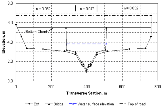 Figure 48. Cross sections and water-surface elevation for Burdell Creek bridge. (Drainage area = 971 km2, Q100 = 397 m3/s). Now the scour parameters can be calculated from the WSPRO results. The value of M(K) from table 5 is 0.189, which by definition gives M = 1 - M(K) = 0.811. For consistency with the current FHWA methodology, the unconstricted and constricted floodplain depths and velocities are determined by the procedure given in HEC-18 for Froehlich's equation. First, for the constricted case, the abutment length is determined from table 5 as the difference between the left edge of the water (LEW) for the BRDG and APPR sections:
Then, from table 7 for the constricted flow, the blocked flow in the approach section up to X STA. = LEWBRDG is 1.97 streamtubes by interpolation. Therefore, the blocked flow Qf1 is (1.97/20)397 = 39.1 m3/s (1380 ft3/s), because each of the 20 streamtubes carries 1/20 of the total flow. Also, the blocked flow area Af1 can be interpolated from table 7 to be 106.8 m2 (1150 ft2). Now we can calculate Vf1 = Qf1/Af1 = 39.1/106.8 = 0.366 m/s (1.20 ft/s), and yf1 = Af1/La = 106.8/233 = 0.458 m (1.50 ft). In a similar manner, the value of yf0 is found for the equivalent blocked flow area in the unconstricted cross section from table 6 to be 0.357 m (1.17 ft). The critical velocities for coarse sediments are determined by substituting into equation 55 (Keulegan's equation). For the constricted approach section, we have for a floodplain depth of 0.458 m (1.50 ft):
where Shields' parameter was taken to be 0.035 for this sediment size.(75) Because Vf1 Vf1c, it is apparent that we have clear-water scour. In a similar manner, the value of Vf0c for an unconstricted floodplain depth of 0.357 m (1.17 ft) is 0.59 m/s (1.93 ft/s). To compute the scour depth for the setback abutments, substitute into equation 56 to obtain:
where shape factor KST = 0.77 from equation 57. Finally, the scour depth is 4.44 x 0.357 = 1.59 m (5.22 ft). In general, this calculation would be repeated for the right abutment; however, this example has an essentially symmetrical cross section. The NFF program can be used to develop a design flood hydrograph. Assuming that the watershed is 48.3 km (30 mi) long with a lag time of 15 hours, the resulting hydrograph can be computed and is shown in figure 49. As a conservative assumption, the flood duration is estimated as the time required for a constant discharge equal to the peak discharge to give the 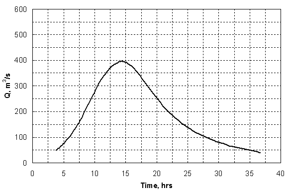 Figure 49. Design 100-year hydrograph for Burdell Creek. (Drainage area = 971 km2, lag time = 15 hours). same volume of direct runoff as the original hydrograph. This results in a duration of 13.4 hours. The critical velocity at the toe of the abutment is computed from a depth equal to the water-surface elevation in the bridge opening, which is 3.80 m (12.47 ft) from table 5 minus the ground elevation at the toe (3.15 m) to give yab = 0.646 m (2.12 ft). Then, using equation 55 again for consistency, the critical velocity Vc = 0.64 m/s (2.1 ft/s), and Vct/yf0 = (0.64)(13.4)(3600)/(0.357) = 9 x 10⁴. From equation 59, Vab/Vc = 1.54, and figure 41 indicates that approximately 90 percent of the equilibrium scour will occur over the estimated flood duration of 13.4 hours. Under these circumstances, the reduction in scour caused by equilibrium not being reached is small so that the final result for the clear-water abutment scour depth is left at the value of 1.59 m (5.22 ft) that was previously estimated. Because scour holes can develop as a result of several floods over time, the time analysis proposed herein is intended as a judgment factor in reducing the estimated scour only when: (1) the estimated scour is significantly higher than that actually observed on an existing bridge, or (2) the watershed is so small that only a small fraction of equilibrium scour is reached in a typical design flood. It is strongly recommended that a whole range of discharges be considered and that the percentage of equilibrium scour be investigated in each case. Figure 41 provides the first method for estimating the percentage of equilibrium scour for floods of differing magnitude, and it should greatly enhance the engineer's judgment in making a final evaluation of scour susceptibility. It should be noted that the estimated equilibrium scour has been determined for a spill-through abutment with a shape factor of 0.77 for this particular example, which is greater than the value of 0.55 currently recommended by HEC-18. However, the shape factor varies and can be as large as 1.0 for long spill-through abutments as indicated by equation 57 (shape has no influence in some cases). In addition, the estimated scour could be increased by a skewness factor for abutments not perpendicular to the flow as recommended by HEC-18; however, for this example, the skewness factor was taken to be 1.0 for a perpendicular abutment. Finally, for the purposes of comparison, it is reasonable to calculate the abutment scour for this case by using Froehlich's live-bed scour equation or the HIRE (Highways in the River Environment) equation as recommended by HEC-18. Substituting into Froehlich's equation, given previously as equation 5, and using the values of La, yf1, and Vf1 already determined, we have:
so that ds = (7.24)(0.458) = 3.32 m (10.9 ft), which is approximately twice as large as the value estimated by the procedure proposed herein. For the HIRE equation, which is recommended by HEC-18 for long abutments, the value of yab is taken to be 0.646 m (2.12 ft) as determined previously from the water-surface elevation in the bridge section. However, the value of Vab is estimated to be equal to 0.98 m/s (3.2 ft/s) as determined from figure 30 or equation 59 developed in this research. The use of the WSPRO results from the bridge section to estimate Vab is not recommended because conveyance ratios cannot predict the local acceleration occurring near the abutment face. Now, substituting into the HIRE equation given by equation 15 in chapter 2, we have:
Then, if we add an FS of 1.0 for consistency with the other methods used, ds = (3.9)(0.646) = 2.52 m (8.3 ft). This estimated scour depth lies between the one predicted from the results of this research (1.59 m) and the one from Froehlich's live-bed scour equation (3.32 m). The HIRE equation necessarily assumes live-bed scour, because there is no dependence on sediment size. In this example, live-bed scour is not predicted to occur. COMPARISON WITH FIELD DATAField data for the flood of April 1997 on the Pomme de Terre River in Minnesota were measured by Mueller and Hitchcock(93) of the USGS and were provided to the author by Sterling Jones(94) of FHWA. A bridge scour investigation report for the bridge over Highway 12, including a WSPRO data file, was also made available.(95) Xibing Dou(96) provided his spreadsheets of the cross-sectional data for Highways 12 and 22 to the author. New WSPRO runs were made by the author for each bridge, and scour calculations were carried out according to the methodology presented in this report. First, the downstream water-surface elevation at the exit section was adjusted for the measured discharge until the measured water-surface elevation at the bridge during the flood was reproduced. The bridge cross section after scour was used in these computer runs. Then, WSPRO runs were made using the cross sections before scour to obtain the necessary information for the scour predictions. The cross-section data for Highway 22 were more limited than that for Highway 12, so a template cross section was used to provide all of the necessary cross-section data in agreement with a measured river bed profile before scour. Highway 22 Example The Swift County Highway 22 bridge crosses the Pomme de Terre River near Artichoke Lake in Minnesota, about 10 km upstream from the Highway 12 bridge. The abutments are set at the edge of the main channel, and there are two bridge piers with a spacing of approximately 12.2 m (40.0 ft) as shown in figure 50. (The horizontal stations were established as increasing from right to left; however, the distances are given as negative numbers in the figure so that they are increasing from left to right while looking downstream.) The abutments are protected by rock riprap on a 2:1 sideslope. On April 5, 1997, a discharge of 129.5 m3/s (4570 ft3/s) was measured, and scour began to develop near the right abutment. On April 9, the discharge was measured as 145.9 m3/s (5150 ft3/s) and the bridge was temporarily closed until riprap could be placed to 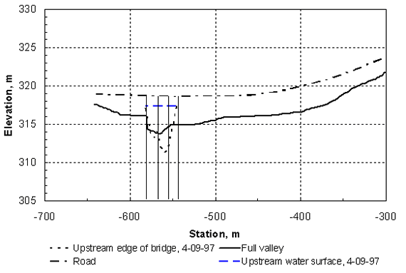 Figure 50. Cross sections for Highway 22 over the Pomme de Terre River for the flood of April 9, 1997. protect the bridge. The minimum bed elevation reached on that date was 311.3 m (1021.5 ft) as shown in figure 50. The bed material from elevation 312.4 m (1025.0 ft) downward is shown on the Minnesota Department of Highways bridge survey as being fine gravel. From the after-scour WSPRO run for the measurements taken on April 9, it was determined that a water-surface elevation of 317.21 m (1040.96 ft) at the exit cross section gave an elevation of 317.25 m (1040.90 ft) at the downstream face of the bridge for Q = 145.9 m3/s (5150 ft3/s). Adding a drop of 0.09 m (0.30 ft) in the water surface through the bridge measured on April 4 at nearly the same discharge resulted in a water-surface elevation on the upstream face of the bridge of 317.34 m (1041.20 ft) in agreement with the measured value on April 9. The before-scour WSPRO run was then made with the same tailwater elevation at the exit section as for the after-scour run. The input data file is given as table 8, and the results are given in tables 9 through 11, from which the necessary information is obtained for the scour computations. The value of the discharge distribution factor from table 9 is M = 1 - M(K) = 0.336.1 The computations are made for the right abutment where the deepest scour occurred because of the wider floodplain on that side. The detailed procedure for making the computations has already been given in the previous example, so only the main results are highlighted in this field application. In table 9, the length of the abutment on the right side is determined to be 174.6 m (573 ft), and the water-surface elevation at the approach section can be obtained. From tables 10 and 11 for the velocity distributions at the approach section for the unconstricted and constricted water-surface elevations, respectively, it is determined that yf0 = 1.55 m (5.08 ft), Vf1 = 0.24 m/s (0.79 ft/s), and yf1 = 1.67 m (5.48 ft). The median grain diameter d50 of the sediment is taken to be 2.0 mm, from which the critical velocity in the main channel of the bridge section is 0.87 m/s (2.85 ft/s) using Keulegan's equation, but substituting the hydraulic radius for the depth. From table 10, the velocities are all less than this critical velocity so that no sediment of the size being scoured could be carried into the scour hole (clear-water scour). The scour depth is then determined as clear-water scour around a bankline abutment from equation 56 using the shape factor for a spill-through abutment of 0.67, which is calculated from equation 57. The result is:
The scour depth measured from the unconstricted water surface at the bridge is then ds + yf0 = (2.64)(1.55) + 1.55 = 5.6 m (18.4 ft) so that the bottom elevation in the scour hole is the water-surface elevation of 317.3 m (1041.0 ft) at the full valley section minus 5.6 m, or an elevation of 311.7 m (1022.7 ft). For comparison, the lowest measured bed elevation is 311.3 m (1021.4 ft), which is well within the standard error of the scour-prediction formula. Also, no FS has been included in the computation. If it is included, the predicted bottom elevation is 310.1 m (1017.4 ft), which provides a reasonable margin of safety. Highway 12 Example The second field example comes from the same flood on the Pomme de Terre River, but at the bridge on Highway 12 near Holloway, MN. The bridge was closed because of scour at the right abutment that extended below the abutment footing. The bridge is a single span with a length of 26.8 m (88.0 ft), and it has vertical abutments with 45-degree wingwalls. The channel and bridge cross sections are shown in figure 51. The measured discharge on April 9, 1997, was 162.9 m3/s (5750 ft3/s), with a measured water-surface elevation on the upstream side of the bridge of 302.6 m (993.0 ft). The minimum bed elevation was measured to be 293.5 m (963.0 ft) near the right abutment. The surficial sediment in the streambed is described as "organic, silty sand" with a d50 of 0.15 mm; however, the boring log shows that the material below about an elevation of 305 m (1000 ft) is "sand and gravel, gray, saturated." From the after-scour WSPRO run, the exit tailwater elevation was determined to be 302.6 m (992.8 ft) for a discharge of 162.9 m3/s (5750 ft3/s). The input data file for the before-scour WSPRO run is given in table 12, and the WSPRO results are shown in tables 13 through 15. The value of the discharge distribution factor from table 13 is M = 1 - M(K) = 0.335. The computations are made for the right abutment (west) where the deepest scour occurred. From table 13, the length of the abutment on the right side is determined to be 121.3 m (398.0 ft), and the water-surface elevations at the approach section can be obtained. From tables 14 and 15 for the velocity distributions at the approach section for the unconstricted and constricted water-surface elevations, respectively, it is determined that yf0 = 1.12 m (3.67 ft), Vf1 = 0.19 m/s (0.62 ft/s), and yf1 = 1.22 m (4.00 ft). If the median grain diameter d50 of the sediment is taken as 2 mm in the scour-hole region as done for Highway 22, the critical velocity in the main channel of the approach section is 0.88 m/s (2.89 ft/s) using Keulegan's equation. However, the WSPRO results in table 15 show maximum approach velocities of approximately 0.84 m/s (2.76 ft/s). For practical purposes, this means that the scour is approaching threshold live-bed scour. Thus, for live-bed scour around a bankline abutment, equation 58 is used with Vm1 = Vm1c. Because M is relatively small, equation 58 indicates that the maximum value of ds/yf0 = 10 has been reached. The scour depth measured from the water surface in the bridge before scour is then ds + yf0 = (10)(1.12) + 1.12 = 12.3 m (40.4 ft), so that the bottom elevation in the scour hole is the unconstricted water-surface elevation of 302.6 m (992.9 ft) at the full valley section minus 12.3 m, or an elevation of 290.3 m (953 ft). For comparison, the lowest measured bed elevation is 293.5 m (963 ft), which is approximately 3 m higher than predicted. Given the presence of both sand and gravel, it is likely that armoring occurred, which limited the scour-hole depth in comparison to the predicted value; however, there is simply not enough information available on the sediment size distribution for this example, so these results are somewhat inconclusive. 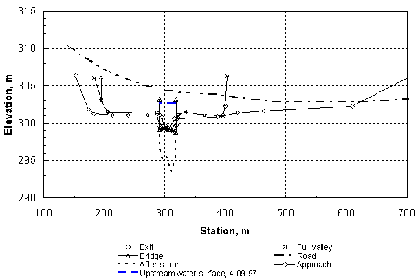 Figure 51. Cross sections for Highway 12 over the Pomme de Terre River for the flood of April 9, 1997. LIMITATIONSThe experimental results developed herein are for the case of clear-water abutment scour in a compound channel with a wide floodplain. The ranges of variables covered in the experiments reported herein are given in table 3.
1 Alternatively, the value of M could be determined from the centerline of the main channel to the right edge of water in the approach section using the velocity distribution in Table 11, but it makes only a small difference in the result in this case. |