U.S. Department of Transportation
Federal Highway Administration
1200 New Jersey Avenue, SE
Washington, DC 20590
202-366-4000


Skip to content
Facebook iconYouTube iconTwitter iconFlickr iconLinkedInInstagram

Federal Highway Administration Research and Technology
Coordinating, Developing, and Delivering Highway Transportation Innovations

Report
This report is an archived publication and may contain dated technical, contact, and link information
Publication Number: FHWA-HRT-06-133
Date: March 2007

The Use of Lithium to Prevent Or Mitigate Alkali-Silica Reaction in Concrete Pavements and Structures

Chapter 5. Use of Lithium to Treat Existing ASR-Affected Structures

5.1 Laboratory Studies

A number of laboratory studies (Stark et al., 1993; Stokes et al., 2000) have demonstrated that treating ASR-affected concrete with lithium compounds can reduce or eliminate future expansion due to ASR (e.g., figure 19). Typically, such studies have used laboratory-sized specimens with relatively small cross-sections and it has not yet been demonstrated that lithium treatment is effective with larger specimens that are more representative of elements of concrete structures.

Figure 19. Graph. Expansion of concrete prisms after treatment with lithium at 10 weeks (expansion equals 0.061 percent) and 16 weeks (expansion equals 0.107 percent) (Thomas and Stokes, 2004). The X-axis is the age in weeks, and the Y-axis is the expansion rate in percentage. There are three lines made from connecting points, each rising from left to right. The black line, representing expansion measurements of the control prisms, begins from zero on the lower left corner of the graph and increases to around 0.2 percent expansion at close to 80 weeks. The red line, representing expansion measurements of concrete prisms treated at 10 weeks, begins with an expansion over 0.05 percent at about 10 weeks and ends with an approximate expansion rate of 0.13 percent at about 80 weeks. The blue line, representing expansion measurements of concrete prisms treated at 16 weeks, begins with an expansion over  0.10 percent at about 16 weeks and ends with an approximate expansion rate of 0.14 percent at abut 80 weeks.

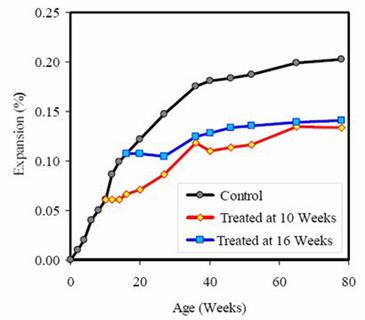
Figure 19. Expansion of concrete prisms after treatment with
lithium at 10 weeks (expansion = 0.061 percent) and 16 weeks
(expansion = 0.107 percent) (Thomas and Stokes, 2004).

5.2 Field Applications

5.2.1 Topical Treatment with Lithium

Numerous structures have been treated by spraying the surface of the structure with a solution of lithium (both LiNO3 and LiOH have been used). These structures have included pavements, bridge decks and other bridge components, and median barriers. The solution has been applied by either truck-mounted spraying systems (figure 20) or hand-held pressurized spray bottles (figure 21).


Figure 20. Photo. Spraying 30-percent lithium nitrate solution with a tanker truck on a concrete pavement near Mountain Home, Idaho. This photo shows a closeup view of a water truck spraying lithium nitrate on an A S R-affected pavement near Mountain Home, Idaho.

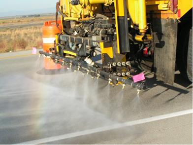
Figure 20. Spraying 30 percent LiNO3 solution with a tanker
truck on a concrete pavement near Mountain Home, ID.

Figure 21. Photo. Spraying 30-percent lithium nitrate solution with handheld spray applicator on a barrier wall near Leominster, Massachusetts. This photo shows a worker using a handheld spray applicator to topically spray lithium nitrate on an A S R affected concrete barrier. The barrier is part of a median structure on a highway. There is extensive cracking in the barrier, and the top of the barrier is moistened with the lithium nitrate.

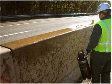
Figure 21. Spraying 30-percent LiNO3 solution with handheld
spray applicator on barrier wall near Leominster, MA.

Typical application rates have been in the range of 0.12 to 0.24 liters per square meter (L/m2) (3 to 6 gallons per square feet (gal /1000 ft2)). The most commonly used lithium compound for this purpose is a 30 percent LiNO3 solution. Commercially available solutions contain a proprietary surfactant to enhance penetration.

There are few data available regarding the depth of lithium penetration following lithium treatment. Figure 22 shows lithium concentration profiles in concrete cores cut from a pavement after six treatments (one treatment in each of spring and fall for 3 consecutive years) of 0.24 L/m2 (6 gal/1000 ft2). The depth of lithium penetration is clearly dependent on the extent of cracking.
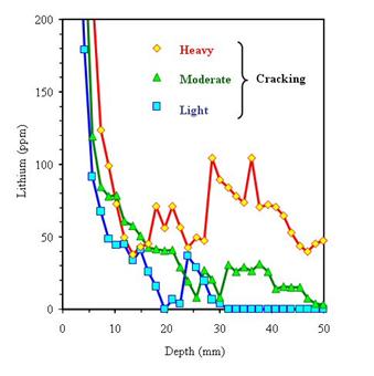
Figure 22. Graph. Lithium concentration profiles for concrete pavement after six treatments (at approximately 6-month intervals) of 0.24 liters per square meter (6 gallons per 1,000 square feet) (Stokes et al. 2002). The X axis on this chart is the depth of penetration in millimeters, and the Y axis shows the lithium amount in parts per million. Three lines made from connected points are shown in this chart. The blue line represents light cracking, the green line represents moderate cracking, and the red line represents heavy cracking. The chart shows that the lithium penetration is dependent on the extent of cracking.

1 mm = 0.039 inch

Figure 22. Lithium concentration profiles for concrete pavement after six treatments
(at approximately 6-month intervals) of 0.24 L/m2 (6 gal/1000 ft2) (Stokes et al., 2002).

Figure 22 indicates that very little lithium penetrates below 25 to 50 mm (1 to 2 inches) unless the concrete is heavily cracked. Even in heavily cracked concrete, the lithium concentration at this depth is low, and its ability to suppress ASR is questionable[3].

Most of the structures that have been treated topically with lithium have not been monitored properly (i.e., other than by simple visual inspection) to confirm whether the treatment has been effective in terms of suppressing ASR expansion.

5.2.2 Electrochemical Lithium Impregnation

Electrochemical impregnation techniques have been used to increase lithium penetration on a number of structures (Whitmore and Abbot, 2000). A typical setup (i.e., for a bridge deck) is shown in figure 24 and includes the following parameters:

  • Technique is based on electrochemical chloride extraction technique.
  • Electrode (anode) applied to concrete surface.
  • Lithium-bearing electrolyte ponded at surface.
  • D.C. voltage (~40 volts) applied between surface anode and embedded steel (cathode).
  • Positively charged lithium ions are repelled by the positively charged anode and are drawn towards the negatively charged cathode (steel reinforcement).
  • Duration of treatment is typically 4 to 8 weeks.

Figure 23. Illustration. Electrochemical lithium impregnation. This illustration shows a steel bar (representing steel reinforcement in a concrete structure) in a rectangle representing hardened concrete. A blue rectangle, labeled “lithium salt electrolyte,” runs across the top of the rectangle representing hardened concrete. A black dashed line runs across the length of the blue rectangle. Five red arrows are pointing down from the blue rectangle to the concrete steel reinforcement, representing the positively-charged lithium ions being drawn into the concrete. Outside the rectangles, the dashed line and the steel reinforcement bar are connected by a voltage connection. The typical electrochemical lithium impregnation setup is described in section 5.2.2 of the text.

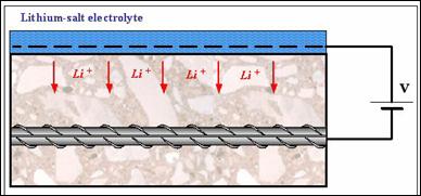
Figure 23. Electrochemical lithium impregnation.

Two such cases of using this electrochemical technology have been documented in the literature; these are two bridge decks, one in Arlington, VA, the other in Seaford, DE. In both cases, lithium borate was used as the electrolyte. Cores were taken from the deck in Virginia after 8 weeks of electrochemical treatment. Slices taken from the cores and subjected to chemical analysis revealed the data shown in
table 11.

Table 11. Penetration of lithium after electrochemical
treatment of bridge deck.

Depth of slice (mm) Lithium (ppm)

6-19

315-343

19-32

203-265

1 mm = 0.039 inch

The data indicate that significant lithium penetrates to a depth of at least 19 to 32 mm (0.75 to 1.25 inches), and these dosages are theoretically high enough to have a beneficial effect on reducing ASR-induced expansion (see footnote 2 in chapter 3).

In March 2006, two columns in Houston, TX, were selected for electrochemical treatment as part of the Federal Highway Association Lithium Implementation Technology Program. Figure 24 shows the process of the treatment for one of the columns. The entire treatment was completed mid-May of 2006.

Figure 24. Photos. Electrochemical lithium treatment process. There are three photos, labeled A, B, and C, of columns in Houston, Texas, that were selected for electrochemical treatment. Photo A shows irrigation tubes, wood splices, and metal strips placed on the column. The metal strips are attached to titanium mesh that runs inside holes drilled into the sides of the column. Photo B shows a cellulose layer being applied to the side of a column. Photo C shows plastic sheeting placed on all sides of the column. The gutters attached under the sheeting collect excess lithium for reuse.

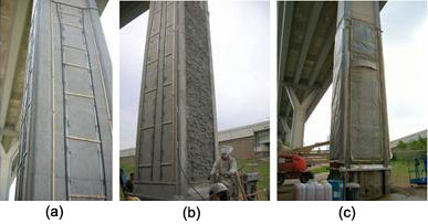
Figure 24. Electrochemical lithium treatment process. (a) irrigation tubes, wood splices, and metal strips are placed on the column. The metal strips are attached to titanium mesh that runs inside holes drilled into the sides of the column. (b) A cellulose layer is applied to the side of the column, and (c) plastic sheeting is placed on all sides of the column. The gutters under the sheeting collect excess lithium for reuse.

5.2.3 Vacuum Impregnation With Lithium

Vacuum impregnation is an alternative to pressure injection and has been used to increase grout penetration into cracked concrete. A number of structures have been treated with lithium using this technique; these include several substructure elements (beams and columns) of the New Jersey Turnpike, a number of elements on the Prospect Avenue Viaduct in Johnstown, PA, a trapezoidal prestressed bridge girder (treated by vacuum impregnation as part of a study of ASR-mitigation methods on 5 girders in Corpus Christi, TX), and sections of a barrier wall on Highway 2 near Leominster, MA (figure 26).

At the time of writing, no data were available concerning the depth of lithium penetration as a result of vacuum impregnation.

  • Double-sided adhesive (e.g. butyl) tape is sealed to the surface around the perimeter of the area to be treated.
  • Plastic mesh is placed on the surface to be treated within the boundry of the tape.
  • Inlet tubes are placed within the area to be treated to distribute lithium.
  • Area to be treated is covered with plastic, which is fixed to the adhesive tape at the perimeter to seal the system.
  • A vacuum is applied to the sealed surface to remove air and moisture in the cracks.
  • Once a steady vacuum (approx 0.5 atmosphere) has been achieved, lithium is drawn into the evacuated area.
Figure 25. Photos. Typical vacuum impregnation setup. Three photos, labeled A, B, and C, are shown. Photo A, at top, shows the side of a concrete barrier with extensive cracking covered by a red plastic mesh taped to it. A spiral plastic tube is adhered to the top of the mesh, near the top of the barrier. Photo B, in the middle, shows workers applying plastic sheeting on top of the red plastic mesh and spiral plastic tube. The sheeting is being adhered to the side of the concrete barrier using double-sided adhesive tape. Photo C, at bottom, shows a closeup view of the side of the concrete barrier with the red plastic mesh along the side of the barrier, the white spiral plastic tube near the top of the barrier, and the plastic sheeting over the barrier. The vacuum has been turned on, and the lithium is being vacuumed across the barrier, first starting in the lower right corner and radiating out towards the center of the barrier. Accompanying bulleted text describes the setup of the vacuum impregnation treatment method. The first bulleted item reads, 'Double-sided adhesive (e.g., butyl) tape is sealed to the surface around the perimeter of the area to be treated.' The next bulleted item reads, 'Plastic mesh is placed on the surface to be treated within the boundary of the tape.' The next bulleted item reads, 'Inlet tubes are placed within the area to be treated to distribute lithium.' The next bulleted item reads, 'rea to be treated is covered with plastic, which is fixed to the adhesive tape at the perimeter to seal the system.' The next bulleted item reads, 'A vacuum is applied to the sealed surface to remove air and moisture in the cracks.' The last bulleted item reads, 'Once a steady vacuum (approximately 0.5 atmosphere) has been achieved, lithium is drawn into the evacuated area.'

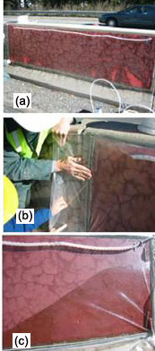
Figure 25. Typical vacuum impregnation setup.

5.3 Recommendations for Treating ASR-Affected Structures with Lithium

Before treating a structure with lithium-based compounds, an investigation should be conducted to ensure that the structure meets the following criteria:

  • The main cause of damage is alkali-silica reaction. Lithium treatment is unlikely to "cure" any other deterioration processes such as freeze-thaw damage, corrosion of embedded steel or even alkali-carbonate reaction. Proper diagnosis involves extracting samples for petrographic analysis and other testing in the laboratory.
  • There remains potential for further expansion and damage due to ASR.

Lithium treatment will not "repair" any damage that has already occurred. A protocol for selecting structures that may be suitable for lithium-treatment is available from FHWA (FHWA-RD-04-113).

Treating structures with lithium is a technology that is still under development and, at this time, recommended protocols for selecting the type of treatment (e.g., topical, electrochemical, or vacuum impregnation) or methodologies for performing the treatment do not exist. Electrochemical and vacuum impregnation require specialized knowledge and equipment, and should be conducted only by an experienced contractor. Topical applications are relatively simple to perform, and a few general guidelines are provided in table 12. Figure 26 shows examples of LiNO3 precipitation after application.


Table 12. General guidelines for topical lithium treatment.

Treatment Procedure
  • Clean surface (e.g., road sweeper) prior to treatment.
  • Do not treat if rain is forecast within 6 hours.
  • Keep single application rate ≤ 0.12 L/m2 (3 gal /1,000 ft2).
  • Minimum two applications.
  • Applications at least 30 minutes apart.
  • Ensure uniform surface coverage and no runoff.
  • If precipitate forms over > 5 percent of surface, re-wet the surface to dissolve the precipitate. If surface becomes slippery, applications of water should continue until the surface is safe for vehicular traffic.

The number of individual treatments that can be applied to a structure will be governed by economics and other aspects of the repair strategy. For example, if the structure is being treated prior to the application of a concrete or asphalt overlay, there may only be time for a single treatment. For pavements or bridge decks that remain exposed after treatment, additional treatments may be considered at appropriate intervals. For example, the treatment of State Route 1 in Delaware involved a total of 6 individual treatments over a 3-year period.

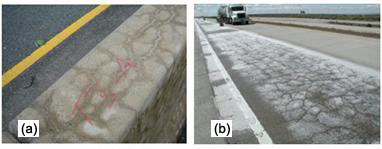
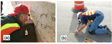
As the efficacy of lithium treatment has yet to be established, it is recommended that treated structures are tested and monitored properly. Some suggestions for monitoring are provided in table 13. Figure 27 shows crack mapping and length change monitoring.

The authors are not aware of any studies aimed at evaluating the effect of lithium nitrate on the environment.

Figure 26. Photos. Precipitation of lithium nitrate from solution (A) on barrier wall and (B) on pavement.. There are two photos, labeled A and B. Photo A, on the left, shows the top of a concrete barrier with extensive cracking and the label ‘T3-A’ written on the top of the barrier. White precipitation of lithium nitrate can be seen in some of the cracks. Photo B, on the right, shows a concrete pavement where half of the width of the travel lane has been sprayed with lithium nitrate. The lithium nitrate has precipitated, and a layer of white can be seen across the treated section. This ‘white sheet’ is the salting out of the lithium nitrate that has collected at the surface of the pavement. General guidelines for topically applying lithium to a concrete pavement are described in table 12.

Figure 26. Precipitation of LiNO3 from solution (a) on barrier wall and (b) on pavement.

Table 13. Suggestions for monitoring lithium-treated structures.

Monitoring Guidelines
  • Take core samples to determine depth of lithium penetration.
  • If possible, maintain untreated control section to compare performance with treated section.
  • Monitor length change of concrete. There are a wide variety of techniques available; one of the simplest being to embed stainless steel reference pins and monitor the change in length between the pins using a demountable mechanical (DEMEC) strain gauge (see figure 27b).
  • Crack mapping techniques can be used to follow damage accumulation.
  • Consider use of non-destructive techniques such as spectral analysis of surface waves (SASW).
  • There are a number of technologies available for performing condition surveys of roads and bridges. Some of these have been employed to follow the progress of damage due to ASR.

Figure 27. Photos. Monitoring techniques—A, crack mapping of a barrier wall and B, measuring length changes on concrete pavement with a demountable mechanical gauge. Two photos, labeled A and B, are shown. Photo A, on the left, shows a researcher looking at the side of an A S R-affected concrete barrier with a magnifying apparatus. Photo B shows a researcher taking expansion measurements on an A S R-affected concrete pavement using a demountable mechanical gauge. Suggestions on treated structures that have been treated with lithium nitrate are described in table 13.

Figure 27. Monitoring techniques-(a) crack mapping of a
barrier wall and (b) measuring length changes on
concrete pavement with a DEMEC gauge.


Federal Highway Administration | 1200 New Jersey Avenue, SE | Washington, DC 20590 | 202-366-4000
Turner-Fairbank Highway Research Center | 6300 Georgetown Pike | McLean, VA | 22101