U.S. Department of Transportation
Federal Highway Administration
1200 New Jersey Avenue, SE
Washington, DC 20590
202-366-4000
Federal Highway Administration Research and Technology
Coordinating, Developing, and Delivering Highway Transportation Innovations
 |
| This report is an archived publication and may contain dated technical, contact, and link information |
|
Publication Number: FHWA-RD-03-093
Date: August 2006 |
|
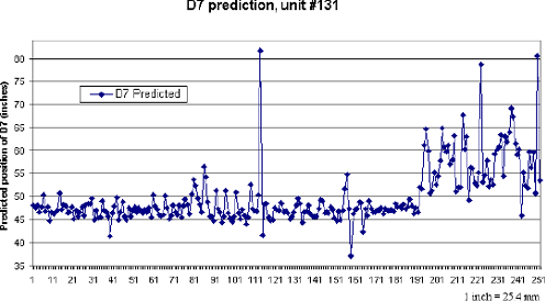
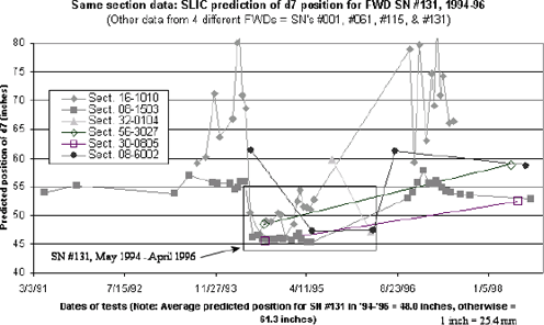
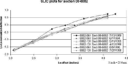
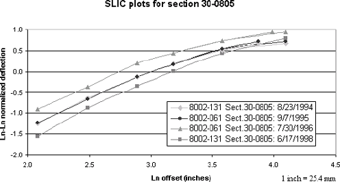
Study of Long-Term Pavement Performance (LTPP): Pavement DeflectionsAppendix K. FWD SN 131, May 24, 1994–April 30, 1996This previously reported (and physically measured) d7 sensor position error was located in the database and also identified and analyzed using an automated screening version of SLIC. This screening version is tailored for sensor 7 (among others), with a close to zero overall bias and the best possible precision (see appendix B). The first graph shown in this appendix (figure 48) is a plot of all the SN #131 d7 sensor position predictions from May 1994 through the middle of March 1997, for all lane 1, drop height 4 FWD tests. In figure 48, it can be seen that the average prediction subsequent to the initial time period where d7 was positioned incorrectly was around 152.4 cm (60 inches), with some scatter due to the relatively large distance between d6 and d7. However, during the period of time in question (May 24, 1994 to April 30, 1996), the average predicted position of d7 is approximately 121.9 cm (48 inches) (average SLIC prediction for all flagged test dates = 120.7 cm (47.5 inches)). In fact, an empty Dynatest sensor holder was originally positioned at 121.9 cm (48 inches) when this unit was delivered. In figure 49, it can be seen that when the same LTPP test sections are plotted as a function of the predicted position of d7, SN #131 for the period May 1994 to April 1996 is an outlier. As shown elsewhere, the average prediction for the d7 sensor is around 121.9 cm (48 inches), which is precisely where it was found in 1996 when a physical measurement was made on this unit of the d7 offset. For the six test sections shown (from four different FWDs), on average the predicted position of d7 was 155.7 cm (61.3 inches), while the same prediction for SN #131 during the period of time in question was 121.9 cm (48 inches). In the two following graphs in this appendix, figures 50 and 51, the same results are shown graphically, with the light gray lines and data points showing the SLIC plot for d7 in both its actual (121.9 cm (48 inches)) and protocol but incorrect (152.4 cm (60 inches)) offset position. The light gray lines that are parallel to the rest of the data are the correct plots, with d7 set to 121.9 cm (48 inches). In the first of these two cases (see figure 50), it can also be seen that the data includes another sensor spacing error for SN #061, namely the 1989 error covered in appendix F. In this case, the SLIC-determined metric sensor positions have been used, which, when transformed, also plot the data for section 08–6002 on a parallel line, for FWD tests conducted on July 13, 1989 (black lines and data points). In the second case (see figure 51), it can be seen as well that the data includes yet another sensor spacing error for SN #061, namely the 1995 error covered in appendix J (also a d7 shift from the 152.4 cm (60 inches) protocol position to 121.9 cm (48 inches)—see the black lines and data points). The medium gray line and data points was from yet another d7 position uncertainty for SN #061; however, in this case the likelihood of a 152.4 cm (60 inches) protocol position is about the same as the SLIC-determined position, approximately 137.2 cm (54 inches). Because of this information, and the previous information supplied to FHWA, it can be concluded with certainty that d7 was positioned at 121.9 cm (48 inches) (or very close to 121.9 cm (48 inches)) on FWD SN #131 between May 24, 1994, and April 30, 1996. These dates correspond to the dates when lane 1 tests were conducted at drop height 4. This period of time may need to be extended slightly, if other tests were conducted along different lanes or at different drop heights. In any case, FWD tests conducted on or after June 12, 1996, indicate protocol sensor positions. Also, it was reported that the regional office moved the sensor back to the 152.4-cm (60-inch) holder at that time. FWD SN #131 was delivered to SHRP and driven to the Western Region shortly before May 24, 1994. Evidently, all tests from the time of delivery through the end of June 1996 were conducted using the SLIC-determined d7 sensor position of 121.9 cm (48 inches) in lieu of the reported protocol position of 152.4 cm (60 inches).
Figure 48. Graph. Predicted position of d7, unit #131, 1994–97.
Figure 49. Graph. Same section data for d7 position, four different FWDs.
Figure 50. Graph. SLIC plots for section 08–6002 including unit #131, May 1995 and April 1996.
Figure 51. Graph. SLIC plots for section 30–0805 including unit #131, August 1994.
|