U.S. Department of Transportation
Federal Highway Administration
1200 New Jersey Avenue, SE
Washington, DC 20590
202-366-4000
Federal Highway Administration Research and Technology
Coordinating, Developing, and Delivering Highway Transportation Innovations
| REPORT |
| This report is an archived publication and may contain dated technical, contact, and link information |
|
| Publication Number: FHWA-HRT-07-040 Date: October 2011 |
Publication Number: FHWA-HRT-07-040 Date: October 2011 |
This appendix describes the new FWD calibration protocol. It is the basis of the current version of the AASHTO R32-09 procedure, Standard Practice for Calibrating the Load Cell and Deflection Sensors for a Falling Weight Deflectometer.(1) AASHTO R32-09 overrules any discrepancies with appendix A.
In May 2010, additional revisions to AASHTO R32-09 were submitted for review and approved by AASHTO. It is anticipated that the revised procedure will be published as AASHTO R32-11. This appendix is supplemental to the forthcoming AASHTO R32-11, and it provides additional background information about the FWD calibration procedures.
This protocol is written for use with the four types of FWDs currently manufactured or sold in the United States. It is not applicable to the calibration of lightweight deflectometers or cyclic loading pavement testing equipment. Due to differences in design of the four types of FWDs, there are some special considerations for each type, which are described in the annexes.
This protocol does not cover the calibration of other parts of FWDs including temperature probes and distance-measuring instruments. The manufacturers’ recommended procedures should be used to calibrate those devices.
This protocol contains two procedures: annual calibration and monthly calibration. The deflection sensors must be removed from their holders on the FWD and installed in a calibration stand for either procedure.
Annual calibration can either be performed at a FWD calibration center or at a site where the FWD is located. The same equipment and procedures are used at both locations. A certified technician is required to perform the procedure. Annual calibration involves two steps: reference calibration and relative calibration. In reference calibration, the FWD’s deflection and load transducers are calibrated against independently calibrated reference devices. In relative calibration, the deflection sensors are compared to each other.
In monthly calibration, only relative calibration of the deflection sensors is completed at any suitable location using the calibration stand supplied by the FWD manufacturer. A certified technician is not required. Monthly calibration is completed for verification of the accuracy of the deflection sensors and occasionally when a sensor must be replaced. The procedure used for monthly relative calibration is different than for annual relative calibration.
The annual and monthly procedures result in gain factors or dynamic calibration factors which are entered into the FWD software as multipliers. When the FWD raw measurements are multiplied by the gain factors, the result is a value which has been corrected to agree with the calibration instrumentation. It is necessary to have a place to enter the gain factors in the FWD operating system software (also known as the field program) provided by the manufacturer.
Annual calibration of the FWD load cell and deflection sensors should be performed at least once per year and as soon as possible after a sensor has been replaced.
Monthly calibration should be performed on the deflection sensors at least once per month and immediately after a deflection sensor has been replaced.
The calibration protocol as described herein has been automated in a software package named WinFWDCal. It can be used for both annual and monthly calibration. Use of the program is required to carry out the procedure.
For annual calibration, the load cell and deflection sensors are calibrated with the goal of adjusting the accuracy (i.e., systematic error) of the devices to ±0.3 percent or better.
Annual calibration requires two people to perform the procedure. One person is the FWD operator, who is responsible for assuring that the FWD is in proper working order for the calibration. During calibration, the operator controls the FWD and removes and replaces the sensors in their holders.
The other person is the calibration operator and is a certified technician. The calibration operator ensures that the calibration equipment is maintained and calibrated as needed. During calibration, this person is responsible for operating the calibration computer and the specialized software used in the calibration of the FWD. In addition, the calibration operator is responsible for providing the documentation of the calibration exercise.
Before beginning a calibration, the FWD operator should present a signed checklist documenting the steps taken in preparation for the calibration, indicating certain preferences concerning the way the calibration should be performed (see annex 1 of appendix A). The FWD operator is responsible for programming the FWD computer to carry out the requested procedure. The FWD operator should provide the history of past calibration results for the FWD.
During calibration, moving the sensors and operating the specialized equipment is a shared responsibility, with the calibration operator having primary control over the calibration equipment. The FWD operator is responsible for transferring the FWD data from the FWD computer to the calibration computer in a format that can be read electronically (including providing a means for the transfers).
After completion of the procedure, the calibration operator should provide the FWD operator with a certificate of calibration that lists the final gain factors for the load cell and each deflection sensor. The FWD operator should enter the final gain factors in the FWD computer and maintain a cumulative history of calibration results in the FWD computer as well as a history of calibration results for the FWD at the calibration center.
Equipment Preparation and Setup Before Calibration
During setup, FWD-specific information will need to be transferred from the FWD operating system (e.g., the FWD field program computer files) to the calibration computer. The annexes in this appendix describe the procedure for obtaining this information for each type of FWD.
FWD
The FWD needs to be in good operating condition prior to performing a calibration. A well-maintained FWD is easier to calibrate and less prone to mechanical and electrical problems during calibration and general use. A checklist to help the FWD operator prepare the FWD for calibration is provided in annex 1. It should be filled out in advance, and a signed copy of the completed checklist needs to be provided to the calibration operator.
Before beginning any calibration work and throughout the entire calibration period, there should not be any data filters turned on in the FWD operating system. The FWD operator is required to verify that all smoothing or filtering has been turned off.
Prior to calibration, the FWD should be warmed up using the standard operating procedure for the particular brand of FWD. After the FWD is moved into position for calibration, it is important that it is level to minimize unwanted vibrations. Trailer-mounted FWDs should also be level to avoid unwanted vibrations.
FWD Drop Sequence
The FWD mass and drop heights/load levels should be set up to produce loads within ±10 percent of the suggested loads shown in table 3. The FWD should be calibrated using three or four load levels. If only three load levels are used, the highest three load levels shown in table 3 should be used.
It is the FWD operator’s prerogative to specify the load levels that will be used for reference calibration. Other load levels may be substituted for those suggested in table 3. The range of loads used should reflect that which FWD normally uses in daily operation. However, in no instance should the combination of static plate load plus maximum dynamic load exceed 24,000 lbf (106 kN). This limitation is required to protect the reference load cell and the concrete pavement used in the calibration procedure.
During setup, the minimum number of drops at each load level will be determined by WinFWDCal based on the deflection response of the concrete pavement or test pad. More than the minimum number of drops may be used without exceeding 10 drops per load level. The FWD operator should program the drop sequence in the FWD computer, progressing from the lowest to the highest load level. The same number of drops should be used at each load level, and the same drop sequence should be used for both load and deflection sensor calibration.
| FWD Brand | Load Level 1 | Load Level 2 | Load Level 3 | Load Level 4 |
|---|---|---|---|---|
| Carl Bro | 6,000 lbf (27 kN) |
9,000 lbf (40 kN) |
12,000 lbf (53 kN) |
16,000 lbf (72 kN) |
| Dynatest® | 6,000 lbf (27 kN) |
9,000 lbf (40 kN) |
12,000 lbf (53 kN) |
16,000 lbf (72 kN) |
| JILS | 9,000 lbf (40 kN) |
12,000 lbf (53 kN) |
15,000 lbf (67 kN) |
18,000 lbf (80 kN) |
| KUAB | 6,000 lbf (27 kN) |
9,000 lbf (40 kN) |
12,000 lbf (53 kN) |
16,000 lbf (72 kN) |
|
Note: The metric and U.S. customary values in this table are not exactly the same. FWD should be calibrated in one unit system or the other. The values in the table are rounded with intervals that are approximately equally spaced. |
||||
The software may inform users that the deflections are either too large or too small to satisfy the precision requirements for reference calibration. The vertical accelerations are also checked to ensure that they do not exceed ±5 g. If the deflection or the acceleration is too large, the FWD should be moved further away from the sensor stand. If the deflection is too small and if three load levels are used, users should try four load levels. If the deflection is still too small and the FWD cannot be moved closer to the sensor stand, users should try a sequence of higher load levels, if possible. If this does not solve the problem, users should find an alternative location to calibrate the deflection sensors.
Table 4 provides information on the equipment needed to perform the load cell and deflection sensor calibration. Detailed information for all components is found in appendix E of this report.
Both reference and relative calibration of all sensors should be performed on concrete pavement. The concrete floor area, or optional concrete test pad, should be in good condition with little or no cracking. The ball-joint base should be attached firmly to the concrete with two anchor bolts to hold the sensor stand in direct contact with the concrete. Additionally, the sensor stand should be clamped tightly in the base. Slippage, rocking, or vibration between the stand and the base or between the base and the concrete is not allowed. The ball-joint should rotate with slight friction.
The reference load cell should be calibrated at least once per year in accordance with the AASHTO R33-03 procedure (see annex 7 of appendix A).(10)
| Equipment | Notes |
|---|---|
| Reference load cell with signal cable | 30,000 lbf (133 kN) maximum capacity; calibrated annually to 24,000 lbf (106 kN) using AASHTO R33-03(10) |
| Reference accelerometer with signal cable | ± 5 g maximum acceleration range, calibrated on the day of use |
| Vishay 2310 or 2310B signal conditioner with power cable | Amplifies the output from the reference devices before analog to digital conversion |
| Keithley KUSB-3108 data acquisition board with cables | Converts the analog output signal into a 16-bit digital value; connected to Vishay and calibration computer |
| Calibration computer and WinFWDCal | Stores the analog-to-digital (A/D) output and performs the calculations needed for the calibration |
| Accelerometer calibration platform | Performs daily calibration of the accelerometer. Also used to store accelerometer in a +1 g field |
| Geophone calibration stand and hardware sets | Designed to be used with Dynatest®, JILS, and Carl Bro geophones; also used with KUAB geophones |
| Seismometer calibration stand | Designed to be used with KUAB seismometers |
| Ball-joint base and anchor | Used with both the geophone and seismometer calibration stands |
| Protective shipping case | For storage and shipping of reference load cell, Vishay signal conditioner, Keithley DAQ, and related cables |
| Isolated concrete test pad | Designed to generate pavement deflections in the desired range; a test pad is recommended but not required |
Accelerometer Calibration
The accelerometer is calibrated in Earth’s gravity prior to use for relative calibration to determine the daily response of the accelerometer. This calibration should be repeated after 8 h have elapsed.
The accelerometer, mounted in an aluminum box, should be calibrated using the calibration platform. The platform should be carefully adjusted using the bubble level to assure that the accelerometer is aligned with Earth’s gravity. The accelerometer needs to be calibrated in both ±1 g fields by inverting the box briefly. Care must be taken to avoid dropping the accelerometer during the calibration process because the shock may cause damage.
WinFWDCal will guide the calibration operator through the accelerometer calibration procedure to calculate the calibration coefficients. The accelerometer box should not be in the -1 g orientation for more than 30 s during the calibration process to minimize the effect of hysteresis on the readings. If it is inverted for a longer period of time, the accelerometer calibration process needs to be stopped. Next, the box should be placed upright in a +1 g field for at least twice as long as it was inverted (up to a maximum of 24 h) to return it to equilibrium. For example, if the box is upside down for 1 min, it should be allowed to equilibrate for at least 2 min before repeating the calibration of the accelerometer.
The accelerometer calibration is slightly temperature sensitive. As a result, it is important that the accelerometer is calibrated shortly before its use. Temperature is monitored continuously by WinFWDCal. The program will alert the calibration operator if the temperature changes by more than ±18 °F (±10 °C). If this occurs, the accelerometer needs to be recalibrated.
It is recommended to complete that deflection sensor calibration first, followed by the load cell calibration. WinFWDCal should be used to collect data and make the associated QA checks.
Table 5 shows the calibration data reporting requirements and the sources of the data. Most of the data are read electronically by the calibration computer from files copied from the FWD operating system. All of the data can be entered or updated manually using WinFWDCal.
Deflection Sensor Calibration
Deflection sensor reference calibration consists of two trials where all of the sensors are calibrated simultaneously in a special stand (see appendix F). The position of the sensors in the stand is inverted between the trials. This is followed by two relative calibration trials using the same stand, where the sensors are inverted once more. Spare deflection sensors should not be calibrated unless they have separate dedicated signal-conditioning channels in the FWD microprocessor.
For reference and relative calibration, the sensor stand should be manually held and kept vertical (as indicated by the bubble level) while data are being collected so the accelerometer box will be correctly aligned with Earth’s gravity. The sensor stand should be supported by the rest stop between trials.
Reference Calibration
Deflection sensor reference calibration consists of performing at least two trials in which all of the sensors are calibrated simultaneously in the sensor stand. The position of the sensors in the stand is inverted between each trial. Spare deflection sensors should not be calibrated unless the FWD has separate dedicated signal-conditioning channels.
The deflection sensors should be placed in the sensor stand and centered on the reference accelerometer. WinFWDCal displays a diagram showing how to arrange the sensors in the stand (see table 8 and table 9 in appendix B).
The drop sequence for the first reference calibration trial should be performed. The operators should review and accept or reject the data for each drop. WinFWDCal will graphically display the deflection time history data after each drop.
Excessive drift from the baseline shown on the time history graph should be cause for rejection of a drop. The software will alert the user when drift is excessive.
At the conclusion of each trial, the user should transfer the data electronically from the FWD to the calibration computer and review the results. For each sensor, WinFWDCal will regress the FWD output (independent variable) versus the reference deflection sensor (dependent variable) forced through zero. The slope of the regression line for each sensor, when multiplied times the initial gain factor, gives the reference gain factor. The slope for an individual sensor is acceptable if its standard error does not exceed 0.0020. The trial is acceptable if the standard errors for all sensors do not exceed 0.0020.
If the first trial is acceptable, the user should continue with the second trial. The sensors in the stand should be inverted before the second trial according to the diagram displayed by WinFWDCal. If any trial is not acceptable, the data should be rejected and the trial is repeated. The user should investigate the reason why the standard error exceeded 0.0020 and correct it, if possible, before repeating the procedure. The user must verify that all sensors are held firmly in the stand.
Interim Gain Factor Acceptance Criteria
After two reference calibration trials have been accepted, WinFWDCal will calculate the average reference gain factor for each sensor and display the results as the interim gain factors (one gain factor for each deflection sensor).
WinFWDCal will calculate the difference in the reference gain factors for each sensor between the two trials. If the difference for each sensor is no more than 0.005, then the reference calibration test is complete. If any of the differences is greater than 0.005, two additional trials should be performed. The user should accept the results and continue but note if any of the differences is more than 0.005. The average of the reference gain factors for all trials for each sensor should be reported as the interim gain factors.
Relative Calibration
Relative calibration is followed by reference calibration and uses the same sensor stand. Two trials are performed. For each trial, 40 drops are applied from the highest drop height used in reference calibration. The sensors should not be repositioned in the sensor stand before the first trial.
WinFWDCal will adjust the FWD data collected in the relative calibration using the interim calibration factors internally. The user should not enter the interim factors in the FWD operating program before performing relative calibration.
To begin, the user should perform the drop sequence for the first relative calibration trial. At the conclusion of each trial, the data should be transferred electronically from the FWD to the calibration computer, and the results should be reviewed. For each sensor, WinFWDCal will calculate the means ratio. The means ratio multiplied times the interim gain factor gives the relative gain factor.
WinFWDCal performs an ANOVA test for the data and reports the standard error. The trial is acceptable if the standard error is not more than 0.12 mil (3 μm) and there are no extreme outliers in the data.
WinFWDCal will display a plot of the data for the 40 drops. The graph should be scanned to detect extreme outliers (i.e., due to a loose sensor in the stand). An extreme outlier would appear substantially outside the normal range of the deflection data.
If the standard error is greater than 0.12 mil (3 μm) or if there are extreme outliers in the data, the first trial is not acceptable, the data should be rejected, and the trial should be repeated. Note that the sensors in the stand should not be repositioned. The reason why the data are unacceptable should be investigated and corrected, if possible, before the procedure is repeated. However, if the first trial is acceptable, the user should continue with the second trial. The sensors in the stand should be inverted before the second trial according to the diagram displayed by WinFWDCal. After two trials have been accepted, WinFWDCal will calculate the average relative gain factor for each sensor and report the results as the final gain factors, completing the deflection sensor calibration procedure.
Note that if two acceptable relative calibration trials cannot be obtained after performing four trials, no further effort should be made to calibrate the deflection sensors.
Load Cell Reference Calibration
If the reference load cell has not been calibrated within the past 12 months, it should be recalibrated in accordance with AASHTO R33-03.(10)
Reference load cell calibration consists of at least two trials. The FWD load plate should not be raised at any time during the procedure. To begin, users should perform the drop sequence for the first reference calibration trial. After, they should review and accept or reject the data for each drop. WinFWDCal will graphically display the deflection time data after each drop.
At the conclusion of each trial, the data should be transferred electronically from the FWD to the calibration computer, and the results should be reviewed. WinFWDCal will regress the FWD output (independent variable) versus the reference load cell (dependent variable) forced through zero. The slope of the regression line for each sensor, when multiplied times the initial gain factor, gives the reference gain factor. The slope for the trial is acceptable if its standard error is not more than 0.0020.
If the first trial is acceptable, the user should continue with the second trial. However, if the first trial is not acceptable, the data should be rejected, and the trial should be repeated. The user should investigate the reason why the standard error exceeded 0.0020 and should correct it, if possible, before repeating the procedure. The load cell should sit squarely under the FWD load plate and squarely on the concrete.
Gain Factor Acceptance Criteria
After two trials have been accepted, WinFWDCal will calculate the average reference gain factor and report the results as the final gain factor. If the range of the two reference gain factors does not exceed 0.003, then the final gain factor should be accepted, completing the load cell calibration procedure.
However, if the results of the first two trials are outside the acceptable range, a third reference calibration trial should be performed. If the standard deviation of the gain factors for three acceptable trials does not exceed 0.003, then the results of the three trials should be averaged and reported as the final gain factor for the load cell, thus completing the load cell calibration procedure.
If the standard deviation of the three trials exceeds 0.003, the reference load cell calibration procedure should be repeated, yielding a fourth reference gain factor. If the standard deviation of all calibrations (four acceptable trials) does not exceed 0.003, the average of all four results should be reported as the final gain factor for the load cell, and the load cell calibration procedure is complete.
If acceptable results cannot be obtained after performing four trials, no further effort should be made to calibrate the load cell.
Evaluation and Acceptance of Final Results
WinFWDCal will perform the needed calculations. The data should be evaluated as follows.
Certificate of Calibration
If the final calibration results meet the acceptance criteria for all sensors according to one or more of the three criteria listed above, the calibration operator should provide the FWD operator with a certificate of calibration listing the final gain factors for the load cell and each deflection sensor. These factors should be entered into the FWD computer. An output file in PDDX format is provided by WinFWDCal to facilitate electronic data transfer.
Report and Retention of Data
The FWD operator should be provided with an electronic copy and a hardcopy of the calibration results. The FWD calibration report should consist of the following:
Calibration records should be retained by the calibration center for at least 5 years.
Monthly calibration serves two purposes. First, it is a means to verify that the deflection sensors are functioning properly and consistently. Second, it can also be used to replace a damaged sensor, providing a short-term gain factor for the replacement sensor until an annual calibration can be performed.
Monthly calibration uses a calibration stand provided by the FWD manufacturer. The deflection sensors are stacked vertically in the stand so that all of the sensors are subjected to the same pavement deflection. Position in the stand may have an effect on the deflection readings. To compensate for this, the sensors are rotated through all positions in the stand. This rotation procedure is different from the relative calibration procedure performed for annual calibration.
Relative calibration relies on collecting a large amount of data that can be averaged to reduce the significance of random measurement errors. Deflections in excess of 20 mil (500 μm) are needed for the results to be accurate. WinFWDCal does the statistical data analysis to compute adjustment ratios and final gain factors from the data.
Since a large number of drops are involved, the properties of the pavement materials may change due to compaction or liquefaction during the procedure. However, all of the sensors are equally affected, and as long as the effect is not too extreme, the adjustment ratios are still accurate.
Some FWDs may have less than seven or more than nine active deflection sensors. If they do, these procedures should be modified to simultaneously calibrate the actual number of active sensors.
FWD
The FWD should be in good operating condition prior to calibration. A well-maintained FWD is easier to calibrate and less prone to mechanical and electrical problems during calibration and during general use. A checklist to help the FWD operator prepare the FWD for calibration is provided in annex 1.
Before beginning any calibration work and throughout the entire calibration period, there should not be any data filters in operation in the FWD operating system. The FWD operator must verify that all smoothing or filtering has been turned off. Additionally, prior to calibration, the FWD should be warmed up using the standard operating procedure for the particular FWD brand.
Other Equipment
Additional calibration equipment includes the FWD calibration stand provided by the manufacturer.
Replicate deflection readings should be taken with the sensors assembled in the calibration stand. With the sensors in a particular position in the stand, two unrecorded seating drops followed by five recorded drops constitute a set. The deflection sensors should be rotated through the various positions in the calibration stand in a prescribed way. The rotation procedure is shown in table 6 for a nine-sensor system and table 7 for a seven-sensor system. The total number of sets of data is equal to the number of sensors on the FWD.
The test point (the location where the FWD load plate is positioned) should be “conditioned” before beginning the calibration procedure to reduce the significance of the set in the data analysis. The warm-up drops should be used for this purpose.
Monthly Calibration of the Deflection Sensors
Follow the WinFWDCal on-screen instructions for setup of the procedure as follows:
Note: The rotation must be performed as prescribed for the data analysis in WinFWDCal to work properly. If the direction of rotation is reversed, the calculations will be incorrect.
Monthly Calibration Data Analysis
The data file should be transferred electronically from the FWD to WinFWDCal for analysis. Options provided in the software indicate whether a normal data analysis or a special analysis is required for sensor replacement.
Adjustment of Gain Factors—Normal Analysis
WinFWDCal will report the adjustment ratios and the gain factors for each deflection sensor. Since sensor replacement is not involved, the adjustment of the gain factors in the FWD operating system should be made only when those changes are both significant and verified to be necessary. The following guidelines should be used to evaluate the need to adjust the gain factors:
Adjustment of Gain Factors—Sensor Replacement
When replacing a damaged deflection sensor, the monthly calibration procedure should be used to determine a gain factor for the replacement sensor. The calculations are performed by WinFWDCal, and a gain factor is reported only for the replacement sensor.
Two relative calibration trials should be performed. If the two gain factors agree within 0.003, then the gain factors for the two trials should be averaged and entered in the FWD operating system, and the calibration test is complete. However, if the difference is greater than 0.003, two more relative calibration trials should be performed. WinFWDCal will report the average gain factor from the four trials and the standard deviation. If the standard deviation is not more than 0.003, then the average gain factor should be entered in the FWD operating system, and the calibration test is complete. If the standard deviation is more than 0.003, no further effort should be made to calibrate the replacement sensor, and the annual calibration procedure should be performed as soon as possible.
Report
The relative calibration report consists of all printouts from WinFWDCal annotated as necessary to explain any problems which may have occurred.
Fill out and bring this checklist with you to the calibration center. Your signature below indicates that you have met all of the pre-calibration requirements.
| FWD Operator: | ________________________________________________________________ |
| FWD ID Numbers: (serial and/or model numbers) |
________________________________________________________________ |
| FWD Manufacturer: | ________________________________________________________________ |
| FWD Owner Agency: | ________________________________________________________________ |
| ☐ | Inspect all connections, fittings, and cables and repair or replace those which are damaged. Damaged cables and bad connections can and will cause inaccuracies in deflection data. | |||
| ☐ | Assure that the load plate swivel is properly lubricated, if applicable, and that all bolts are tight. Refer to your owner’s manual for instructions. Use the 12-inch or 300-mm diameter load plate during calibration. | |||
| ☐ | Remove the rear sensor extension bar if it is currently installed. | |||
| ☐ | Clean and inspect all sensors and signal cables. (Deflection sensors are removed from their holders during calibration.) Fine grained emery cloth is useful for cleaning the magnetic bases of Dynatest® sensors. Remove all stones embedded under the load plate. | |||
| ☐ | Provide a USB thumb drive or a formatted 3½" diskette for transfer of the FWD data to the calibration computer. | |||
| ☐ | Store your operating manuals in the FWD vehicle in case they are needed. | |||
| ☐ | Check the integrity of the batteries with a hydrometer or load tester. Clean the battery terminals and cables of corrosion. | |||
| ☐ | Check hydraulic fluid level(s) and assure that they are at the proper fill point. Inspect the hydraulic system for leaks. Replace the hoses if necessary. | |||
| ☐ | Select the system of units and the load levels to be used for calibration. | |||
| Unit system: | Target load levels: | |||
| ☐ US Customary(lbf) | 1. ___________________ | 2. ____________________ | ||
| ☐ Metric | 3. ___________________ | 4. ____________________ | ||
| Adjust or calibrate the FWD to achieve the target levels within ±10 percent. | ||||
| ☐ | Verify that the proper drop sequences are programmed into the FWD software for both reference and relative calibration. Name and save the setup files. | |||
| ☐ | Turn off filtering (smoothing) in the FWD operating system (if applicable). | |||
| ☐ | Have electronic data files or hardcopies from the previous calibration(s) available. | |||
| Operator’s signature: | ________________________________________________________________________________ | ||
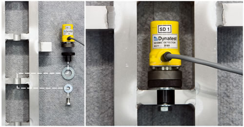
Figure 33. Photo. Attachment of a Dynatest® geophone in the stand.
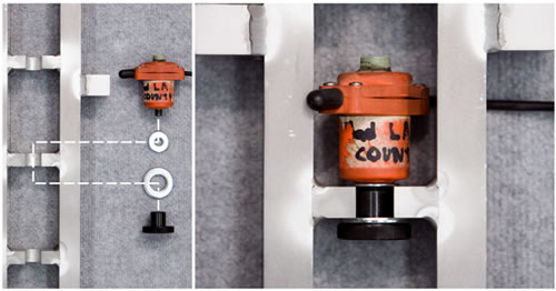
Figure 34. Photo. Attachment of a JILS geophone in the stand.
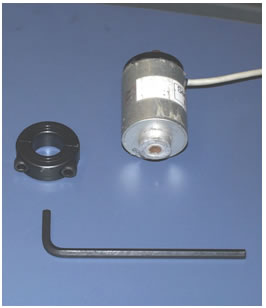
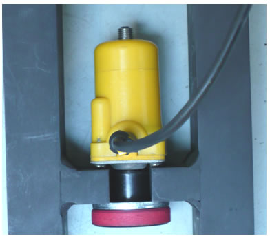
Figure 35. Photo. KUAB geophone parts.
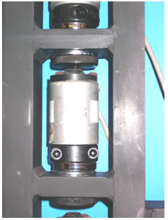
Figure 36. Photo. Attachment of a KUAB geophone in the stand.
Figure 37. Photo. Attachment of a Carl Bro geophone in the stand.
The calibration protocol allows users to perform annual calibrations at locations other than a calibration center. The equipment is highly portable, and it may be advantageous to perform the calibration where the FWD is located rather than shipping the FWD to a center. This procedure is called on-site calibration because it is performed at a site preferred by the FWD owner.
The calibration procedure outlined in appendix A should be used without exception. It must be carried out by a certified calibration center operator as required in AASHTO R 32-09.(1)
A special test pad is not required to be constructed for on-site calibrations. In this regard, AASHTO R 32-09 indicates the following:(1)
While an isolated test pad is recommended, it is not required, provided that all other facilities requirements, especially the minimum slab deflection requirement and sufficient slab damping, are achieved. The slab dimensions (4 by 5 m) are suggested, and other dimensions may be satisfactory … In general, a concrete pavement on a relatively weak subgrade will yield the required deflection amplitude.
As previously noted in this report, the recommended peak deflection is 20 mil (500 µm), and the minimum recommended deflection is 12 mil (300µm). Peak deflection is a useful way to identify suitable locations for performing calibrations. However, deflection is not the limiting criterion. WinFWDCal checks for the following two conditions:
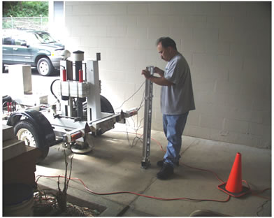
The difficult part of on-site calibration is finding a suitable place to mount the ball-joint anchor and the calibration stand. Figure 38 shows a calibration being performed at the Hawaii Department of Transportation in a breezeway between two buildings. The concrete pavement at this location was relatively thin, and when the FWD was close to the calibration stand, the maximum acceleration exceeded 5 g. To overcome this problem, the FWD trailer was moved about 24 inches (600 mm) in front of the stand, thereby reducing both the peak deflections and maximum accelerations.
Figure 38. Photo. On-site FWD calibration at Hawaii Department of Transportation Materials Lab.
Note that the FWD must be level during the calibration. It is also important to have the calibration equipment protected from the weather at all times. To assess the suitability of a location for FWD calibration, it may be helpful to use the Facilities Review Form found in figure 45 in appendix D.
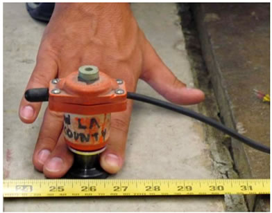
A procedure involving an FWD and one deflection sensor is used to find a place to install the ball-joint anchor. The sensor is removed from its holder and held in place by hand on the pavement. A firm downward pressure is required to keep the sensor in contact with the pavement. A concrete pavement works better than an asphalt pavement because it spreads the deflection basin over a wider area. The procedure is as follows:
Care should be taken to avoid placing the ball-joint anchor too close to a joint or the edge of the pavement. It is often the case that the edge raises before it deflects downward. This can lead to vibration and excess noise problems in the data. Based on experience, a minimum distance of 11.7 inches (300 mm) is recommended between the anchor and the edge of the pavement.
After the ball-joint anchor and the calibration stand have been installed (see figure 39), go through the “Set Trigger” and “Determine Number of Drops” routines in WinFWDCal. Adjust the position of FWD either closer to the calibration stand or further away as needed to get a successful reference calibration.
Once a suitable place for on-site calibration has been found, it can be used repeatedly for future annual FWD calibrations. To protect the two stainless steel inserts from filling up with dirt, it is wise to put an Allen® head set screw in each anchor flush with the top of the holes.
Figure 39. Photo. Locating a place to install the ball-joint floor anchor.
This appendix describes the new reference load cell calibration protocol in detail. It is the basis for the current version of the AASHTO R33-03 procedure.(10) AASHTO R33-03 overrules any discrepancies with this appendix.
The reference load cell is a custom-made precision instrument that is capable of measuring loads within ±0.3 percent or better. However, such a high degree of precision can only be attained if this calibration procedure is followed exactly. It is essential that the reference load cell is calibrated using a universal testing machine that is properly maintained and accurately calibrated.
The reference load cell and its signal cable, the associated signal conditioner, and DAQ should be considered a system of instruments that should be calibrated and used together. The load cell should be calibrated to a maximum load of 24,000 lbf (100 kN).
This procedure is written with both U.S. customary and metric units shown. The calibration operator should choose one unit system and follow the procedure using the values shown. The values are not meant to be a direct conversion. The values are chosen to provide regular steps and ranges with whole numbers where possible.
This procedure has been automated and is included in the RefLCCal computer program.(18)
Calibration of the reference load cell should be performed at least once per year. It should also be performed immediately after any of the machine screws that attach the load measurement links to the upper or lower plates are loosened. Calibration may also be necessary if the load cell fails to pass the unbalanced zero test during FWD annual calibration.
The following list provides information on the necessary equipment for reference load cell calibration:
The universal testing machine should be calibrated annually by a certified technician according to ASTM E-74.(19)The calibrated machine should have a certified accuracy of 1 percent or better. The load indication system used for calibration should be traceable to NIST. The calibration certificate should be evaluated using a multinomial regression procedure to develop an adjustment algorithm (up to fifth order) that adjusts the indicated load on the universal testing machine to the corrected NIST traceable calibrated load. The load calculated by use of the adjustment algorithm is referred to herein as the adjusted load, while the load indicated on the testing machine dial is referred to as the indicated load.
The testing machine calibration coefficients and the date of calibration of the testing machine should be entered into the FWDCalCenterConfig.ini file used by WinFWDCal prior to calibrating a reference load cell.
The Vishay 2310 signal conditioner amplifier should be balanced according to the procedure described in the manufacturer’s instruction manual. With the signal input terminals shorted together, at gain 100, the alternating current (a/c) noise on the ±10-V output terminals should be 1 mV or less.
Load Cell Conditioning
A new load cell or one that has had the lid removed must be conditioned before being calibrated.
Equipment Inspection and Setup
Perform three calibration trials according to the following procedure. WinFWDCal must be used in conjunction with the following step-by-step procedure:
WinFWDCal will perform the data analysis for each trial. It will use a stepup regression utility to calculate a fifth degree polynomial of the form as follows:
Figure 40. Equation. Load cell calibration algorithm.
Where:
Y = The adjusted load calculated from the universal testing machine indicating load including the weight of the upper bearing block.
V = The load cell voltage.
Ai = Coefficients determined by the regression.
Evaluate the results according to the following acceptance criteria:
After completion of at least three acceptable trials, WinFWDCal will pool the data for all three trials and determine regression coefficients based on the combined data, and the calibration is complete.
The final set of calibration coefficients should be evaluated according to the above two criteria. In addition, the three sets of data should be random, neither steadily increasing nor steadily decreasing. This should be verified by reviewing a plot of the residuals versus the fitted values from the regression.
Entering the Coefficients in WinFWDCal
The load cell coefficients should be entered in theFWDCalCenterConfig.ini file. Any of the coefficients that are not found to be significant should be entered as 0.0.
When the regression coefficients are entered in the FWDCalCenterConfig.ini file, the unbalanced zero, the +B and -B calibration factors, and the load cell signal conditioner gain factor should also be entered. This information is used to validate the load cell during FWD calibration.