U.S. Department of Transportation
Federal Highway Administration
1200 New Jersey Avenue, SE
Washington, DC 20590
202-366-4000
Federal Highway Administration Research and Technology
Coordinating, Developing, and Delivering Highway Transportation Innovations
| REPORT |
| This report is an archived publication and may contain dated technical, contact, and link information |
|
| Publication Number: FHWA-HRT-07-040 Date: October 2011 |
Publication Number: FHWA-HRT-07-040 Date: October 2011 |
The purpose of the AASHTO PDDX standard is to foster a uniform file format for output from all types of pavement deflection devices, including FWDs. A harmonized file format allows programmers to develop deflection data analysis programs without the need to provide file readers for the many different native file formats that have been promulgated by equipment manufacturers over time.
While the purpose of this specification is to define a harmonized data format, it is not intended to replace the native file formats of the various manufacturers. Both formats can be provided if the manufacturer chooses. Equipment owners have the option to choose the desired output file format. The PDDX format can be used for static, steady-state vibratory, and dynamic pulse-loading devices, although the primary focus of the Version 2.0 standard is for pulse-loading devices (i.e., FWDs).
The PDDX format puts related data items into sections with descriptive names. It is similar to the .INI format used in Windows®-based configuration files. Each line in the file can either be a section heading or a data entry field with one or more values.
Version 2.0 of the PDDX standard incorporates a few changes from Version 1.0. It reconciles the minor differences that have evolved between the PDDX standard and the input data needs of the AASHTO DARWin pavement design program. DARWin can read PDDX Version 2.0 files. The new version also adds a few data items that were inadvertently left out of Version 1.0. It was necessary to change the name of some data items from Version 1.0, which may require updating PDDX file readers.
The following three types of file formats are described in detail below:
The PDDX file format is used for reporting the results of routine FWD testing of roads and airfields. This format provides data that is collected at multiple test points in a line or a grid pattern.
The FWD calibration record file format contains a historical record of the last calibration that was performed on the FWD. This may be an annual calibration possibly supplemented by monthly calibrations. The file contains information on the date and location where the calibration was performed. It also identifies the special equipment that was used in the calibration. Some sections from the PDDX file format are included in the calibration history file.
Two FWD calibration data exchange file formats are provided. One file is created by the FWD computer and provides information that is needed to begin performing an annual calibration. The data are transferred electronically from the FWD computer to the calibration center computer.
The second file contains the results of the calibration that can be transferred electronically from the calibration center computer to the FWD computer. Both of these files require the cooperation of the FWD manufacturers to provide a means for writing the first file and reading the second one.
Description of Each Data Section and Data Entry Lines
As discussed previously, the data format has a modular structure. Data elements of similar characteristics are grouped together in individual sections. The first line is the section descriptor contained in brackets. Each module contains a number of data items with its associated value or values. Both the added data items and the renamed data items have been identified in the descriptions in bold type.
Pavement Deflection Data Exchange File Section
This should be the initial section in the file. It identifies information related to the PDDX format or version that is being used.
Section
Descriptor [Pavement Deflection Data Exchange File]
PDDX Version Number
| Syntax: | PDDXVersionNumber = number |
| Description: | This entry denotes the current PDDX format version. Depending on the nature and scope of future revisions, the version number of PDDX may change. This is provided to allow for possible changes in the PDDX Standard in the future. |
| Example: | PDDXVersionNumber = 2.0 |
Delimiter Symbol
| Syntax: | DelimiterSymbol = string |
| Description: | A single American Standard Code for Information Interchange (ASCII) printable non-white space character denoting the delimiter symbol. The recommended delimiter symbols include the comma (ASCII character 44), exclamation mark (ASCII character 33), and concatenation symbol (ASCII character 124). |
| Example: | DelimiterSymbol = , |
| Note: | The delimiter symbol and the decimal symbol entries must be mutually exclusive. In the United States, the usual delimiter is the comma, and the usual decimal symbol is the period. |
Decimal Symbol
| Syntax: | DecimalSymbol = string |
| Description: | A single ASCII printable non-white space character denoting the decimal symbol. The internationally accepted decimal symbols include ASCII characters 44 (comma) and 46 (period). |
| Example: | Decimal Symbol = . |
| Note: | The decimal symbol and the delimiter symbol entries must be mutually exclusive. In the United States, the usual delimiter is the comma, and the usual decimal symbol is the period. |
Operations Information Section
This section contains general information recorded once for informational purposes. These data are not used in the analysis of the deflection data; however, they may aid engineers with respect to data analysis by recording time of day and other pertinent information.
Section
Descriptor [Operations Information]
File Name
| Syntax: | FileName = string |
| Description: | This entry identifies the directory location and filename of the PDDX file where the deflection testing data are stored. |
| Example: | FileName = C:\FWD\DATA\SAMPLE.DDX |
Software Version
| Syntax: | SoftwareVersion = string |
| Description: | This entry identifies the software version of the FWD operational software. |
| Example: | SoftwareVersion = 18.9 |
| Note: | This is used by the LTPP database to identify which version of the field program is used to collect the data from FWD. This data field is not in the PDDX standard Version 1.0. |
Start Date
| Syntax: | StartDate = date |
| Description: | Date at onset of testing in dd-mmm-yyyy date format. |
| Example: | StartDate = 28-Apr-2009 |
Start Time
| Syntax: | StartTime = time |
| Description: | Time at the onset of testing in hour:minute:second in 24-h clock format. |
| Example: | StartTime = 07:41:18 |
End Date
| Syntax: | EndDate = date |
| Description: | Date at completion of testing in dd-mmm-yyyy date format. |
| Example: | EndDate = 29-Apr-2009 |
End Time
| Syntax: | EndTime = time |
| Description: | Time at completion of testing in hour:minute:second 24-h clock format. |
| Example: | EndTime = 15:24:12 |
Operator Name
| Syntax: | OperatorName = string |
| Description: | Name of deflection device operator. |
| Example: | OperatorName = Joe Smith |
Weather Condition
| Syntax: | WeatherCondition = string |
| Description: | General description of weather conditions at testing site (e.g., sunny, cloudy, raining). |
| Example: | WeatherCondition = sunny |
This section contains information regarding the units system. All units applicable to the PDDX file format are described in this section. Some units that are unique to FWD calibration are listed in the other file formats.
Note that all units are listed in singular format. English and metric units for applicable data are summarized in table 10. All units used in one PDDX file must be of the same system of units. Thus, a file must use only metric or English measurements. Also, only one unit identifier per data element is allowed for each entry. All permissible unit identifiers are defined below and are case-insensitive.
| Parameter | English System Units | Metric System Units |
|---|---|---|
| Length | Mil | Micron |
| Inch | Millimeter | |
| Foot | Centimeter | |
| Yard | Meter | |
| Mile | Kilometer | |
| Mass | Pound | Kilogram |
| Time | Second | Second |
| Force | Pound-force | KiloNewton |
| Kilopound-force | Kilogram-force | |
| Pressure | Pound-force per square inch | KiloPascal |
| Temperature | Fahrenheit | Celsius |
| Frequency | Hertz | Hertz |
| Angle | Degree-minute-second | Degree-minute-second |
|
1Some of the strings in the table are modified slightly from Version 1.0. |
||
Section
Descriptor [Units]
Load Plate Radius Units
| Syntax: | LoadPlateRadiusUnits = string |
| Description: | The units to be used to identify the radius of the load plate on an impulse load deflection device. The common units of measurement are inches and millimeters. |
| Example: | LoadPlateRadiusUnits = inch |
Load Units
| Syntax: | LoadUnits = string |
| Description: | Units used to measure the magnitude of the applied load (force or pressure) in pound-force, Newton, kiloPascal, or pound-force per square inch. Data with a different unit than the one chosen during calibration setup is converted based upon this data field. |
| Example: | LoadUnits = pound-force |
Deflection Units
| Syntax: | DeflectionUnits = string |
| Description: | Unit used to measure the magnitude of the pavement surface deflection. All deflection sensors must use the deflection unit specified by this entry. The typical units of measurement are mils or microns. Data with a different unit than the one chosen during calibration setup is converted based upon this data field. |
| Example: | DeflectionUnits = mil |
Temperature Units
| Syntax: | TemperatureUnits = string |
| Description: | Unit used to measure temperature data. All temperature sensors must use the temperature unit specified by this entry. |
| Example: | TemperatureUnits = Fahrenheit |
Sensors Location Units
| Syntax: | SensorsLocationUnits = string |
| Description: | Units used to measure the longitudinal and transverse coordinates of deflection sensors with respect to the center of the load plate. |
| Example: | SensorsLocationUnits = inch |
GPS Units
| Syntax: | GPSUnits = string, string, string |
| Description: | Units used to measure global position using a global positioning system (GPS) device. Each GPS unit should be separated by the delimiter symbol. |
| Example: | GPSUnits = degree-minute-second, degree-minute-second, foot |
Test Location Units
| Syntax: | TestLocationUnits = string, string, string |
| Description: | Units used to measure test location distances in an x, y, z coordinate system, with z denoting elevation. Common units are mile, foot, kilometer, and meter. Each test location unit should be separated by the delimiter symbol. |
| Example: | TestLocationUnits = mile, foot, foot |
Nominal Test Spacing Units
| Syntax: | NominalTestSpacingUnits = string |
| Description: | Units used to measure the nominal spacing between test points. |
| Example: | NominalTestSpacingUnits = foot |
Load Frequency Units
| Syntax: | LoadFrequencyUnits = string |
| Description: | Units used to measure the loading frequency of vibratory loading devices. |
| Example: | LoadFrequencyUnits = Hertz |
Drop History Data Frequency Unit
| Syntax: | DropHistoryDataFrequencyUnits = string |
| Description: | Units used to measure the drop history data sampling rate. |
| Example: | DropHistoryDataFrequencyUnits = Hertz |
Joint Crack Width Units
| Syntax: | JointCrackWidthUnits = string |
| Description: | Units used to measure the width of a joint or a crack. |
| Example: | JointCrackWidthUnits = millimeter |
| Note: | This data field is not in the PDDX standard Version 1.0. |
This section contains information regarding the deflection device type, name, and model. Other entries include serial numbers for the overall device, the load plate, and the deflection sensors.
Section
Descriptor [Device Information]
Device Designation Name
| Syntax: | DeviceDesignationName = string |
| Description: | The name of the deflection device being used for testing. |
| Example: | DeviceDesignationName = KUAB 2m-FWD |
Device Model Number
| Syntax: | DeviceModelNumber = string |
| Description: | The model designation for the deflection device being used for testing. |
| Example: | DeviceModelNumber = 8714 |
Device Serial Number
| Syntax: | DeviceSerialNumber = string |
| Description: | The serial number of the deflection device being used for testing. |
| Example: | DeviceSerialNumber = 245 |
Load Cell Serial Number
| Syntax: | LoadCellSerialNumber = string |
| Description: | The serial number of the load cell being used for testing. |
| Example: | LoadCellSerialNumber = LC132 |
Sensor Serial Numbers
| Syntax: | SensorSerialNumbers = string(s) |
| Description: | The serial numbers of each of the deflection sensors being used for testing listed in the same order as the x-axis distances defined in the device configuration section. Each serial number should be separated by the delimiter symbol. |
| Example: | SensorSerialNumbers = 30829, 30830, 30831, 30890, 30832, 30796, 30864 |
Device Load Type
| Syntax: | DeviceLoadType = string |
| Description: | The type of loading device being used for testing (static, vibratory, impulse, or rolling). |
| Example: | DeviceLoadType = Impulse |
This section contains information regarding the exact configuration of the deflection device at the time of testing. Figure 41 provides an illustration of a typical load cell and deflection sensor configuration.
Figure 41. Illustration. Typical load cell and deflection sensor configuration.
Section
Descriptor [Device Configuration]
Load Plate Radius
| Syntax: | LoadPlateRadius = number |
| Description: | Radius of the load plate used during testing. Enter the radius in the units that have been previously specified. |
| Example: | LoadPlateRadius = 5.91 |
Number of Deflection Sensors
| Syntax: | NumberOfDeflectionSensors = number |
| Description: | This entry denotes the number of deflection measuring sensors that are being used for collection of deflection data. |
| Example: | NumberOfDeflectionSensors = 9 |
Deflection Sensor X-Axis Distances
| Syntax: | DeflectionSensorXAxisDistances = number(s) |
| Description: | This entry denotes the x-coordinate of each deflection sensor with respect to the center of the load plate. The x-direction is typically measured in the direction in which the deflection device is traveling. Negative distances are behind the load plate. |
| Example: | DeflectionSensorXAxisDistances = 0, 12, 24, 36, 48, 60, 72, -12, 0 |
| Note: | Generally, FWD collects data in the order of the data acquisition channels. Therefore, the x and y distances should correspond to the arrangement in which the deflection sensors are connected to the data acquisition channels. Thus, if channel 1 corresponds to the sensor in position (0,0) and channel 2 corresponds to position (12,0), they should be listed in that order. |
Deflection Sensor Y-Axis Distances
| Syntax: | DeflectionSensorYAxisDistances = number(s) |
| Description: | This entry denotes the y-coordinate of each deflection sensor with respect to the center of the load plate. The y-direction is typically perpendicular to the direction in which the deflection device is traveling. Negative distances are to the right of the load plate. |
| Example: | DeflectionSensorYAxisDistances = 0, 0, 0, 0, 0, 0, 0, 0, -12 |
| Note: | Generally, FWD collects data in the order of the data acquisition channels. Therefore, the x and y distances should correspond to the arrangement in which the deflection sensors are connected to the data acquisition channels. Thus, if channel 1 corresponds to the sensor in position (0,0) and channel 2 corresponds to position (12,0), they should be listed in that order. |
Number of Temperature Sensors
| Syntax: | NumberOtTemperatureSensors = number |
| Description: | Number of sensors used to collect temperature data. |
| Example: | NumberOtTemperatureSensors = 3 |
Temperature Sensor Use
| Syntax: | TemperatureSensorUse = string(s) |
| Description: | Description of the item for which each temperature sensor is recording the temperature at the time of testing. Options for the item description include air, pavement surface, pavement middepth, and pavement bottom. |
| Example: | TemperatureSensorUse = air, surface, middepth |
Load Frequency
| Syntax: | LoadFrequency = number |
| Description: | The loading frequency used for vibratory testing devices. Note that the frequency value should correspond with the previously entered load frequency unit. |
| Example: | LoadFrequency = 25 |
This section contains information regarding the equipment manufacturer's calibration of the deflection device as well as the results of the most recent annual calibration and monthly calibration. Annual calibration is conducted on FWDs for the load cell and deflection sensors to ensure that all readings are accurate within specified limits.
Section
Descriptor [Device Calibration]
Load Cell Manufacturer Calibration Date
| Syntax: | LoadCellManufacturerCalibrationDate = date |
| Description: | Date of the most recent load cell calibration in dd-mmm-yyyy date format. |
| Example: | LoadCellManufacturerCalibrationDate = 27-Sep-1991 |
| Note: | This calibration date is the FWD manufacturer’s load cell calibration. Usually done only upon delivery or major work on the machine, it is not the annual calibration date. This field is named load cell calibration date in Version 1.0. |
Load Cell Manufacturer Calibration Factor
| Syntax: | LoadCellManufacturerCalibrationFactor = number |
| Description: | Calibration factor obtained from the most recent calibration of the load plate load cell. |
| Example: | LoadCellManufacturerCalibrationFactor = 10956 |
| Note: | This calibration factor is the FWD manufacturer’s calibration. Usually done only upon delivery or major work on the machine, it is not an annual calibration gain factor. This field is named load cell calibration factor in Version 1.0. |
Load Cell Manufacturer Calibration Intercept
| Syntax: | LoadCellManufacturerCalibrationIntercept = number |
| Description: | The y-intercept of the linear relationship developed for calibration of the load cell. |
| Example: | LoadCellManufacturerCalibrationIntercept = 174 |
| Note: | This calibration intercept is the FWD manufacturer’s calibration. Usually done only upon delivery or major work on the machine, it is not the annual calibration factor. This field is named load cell calibration intercept in Version 1.0. |
Load Cell Annual Calibration Date
| Syntax: | LoadCellAnnualCalibrationDate = date |
| Description: | Date of the most recent reference calibration of the FWD load cell in dd-mmm-yyyy date format. |
| Example: | LoadCellAnnualCalibrationDate = 27-Sep-2009 |
| Note: | This is the date of the most recent annual calibration of the load cell. This data field is not in the PDDX standard Version 1.0. |
Load Cell Annual Calibration Gain
| Syntax: | LoadCellAnnualCalibrationGain = number |
| Description: | The multiplier that adjusts the measured values from FWD to match the output from the reference load cell. |
| Example: | LoadCellAnnualCalibrationGain = 1.003 |
| Note: | This is the final gain factor for the FWD load cell determined by using the annual calibration procedure. This data field is not in the PDDX standard Version 1.0. |
Sensor Static Calibration Date
| Syntax: | SensorStaticCalibrationDate = date |
| Description: | Date of most recent deflection sensors static calibration in dd-mmm-yyyy date format. |
| Example: | SensorStaticCalibrationDate = 27-Apr-1992 |
| Note: | The static calibrations are only done with a KUAB FWD. The static calibration of seismometers is performed through the use of a built-in micrometer on the top of each sensor. |
Sensor Static Calibration Factors
| Syntax: | SensorStaticCalibrationFactors = number(s) |
| Description: | Static calibration is conducted for deflection devices utilizing seismic displacement transducers (seismometers) for deflection measurement under a static condition (no pavement loading). |
| Example: | SensorStaticCalibrationFactors = 0.573, 0.553, 0.420, 0.300 |
| Note: | The static calibrations are only done with a KUAB FWD. The static calibration of seismometers is performed through the use of a built-in micrometer on the top of each sensor. |
Sensor Manufacturer Calibration Date
| Syntax: | SensorManufacturerCalibrationDate = date |
| Description: | Date of most recent deflection sensors dynamic calibration in dd-mmm-yyyy date format. |
| Example: | SensorManufacturerCalibrationDate = 27-Apr-1992 |
| Note: | This is the manufacturer’s deflection sensor calibration date. This field is named sensor dynamic calibration date in Version 1.0. |
Sensor Manufacturer Calibration Factors
| Syntax: | SensorManufacturerCalibrationFactors = number(s) |
| Description: | Dynamic calibration is conducted for deflection devices with seismometers to relate the sensor’s dynamic to static behavior. |
| Example: | SensorManufacturerCalibrationFactors = 1.050, 1.050, 1.050, 1.050 |
| Note: | This is the FWD manufacturer’s deflection sensor calibration factor. For example, in the Dynatest® FWD, this is labeled the absolute gain factor. This field is named sensor dynamic calibration factor in Version 1.0. |
Sensor Annual Calibration Date
| Syntax: | SensorAnnualCalibrationDate = date |
| Description: | Date of most recent deflection sensor annual calibration in dd-mmm-yyyy date format. |
| Example: | SensorAnnualCalibrationDate = 27-Apr-2009 |
| Note: | This is the date that the deflection sensors were most recently calibrated using the annual calibration procedure. This field is named sensor reference calibration date in Version 1.0. |
Sensor Monthly Calibration Date
| Syntax: | SensorMonthlyCalibrationDate = date |
| Description: | Date of most recent deflection sensor annual calibration in dd-mmm-yyyy date format. |
| Example: | SensorMonthlyCalibrationDate = 27-May-2009 |
| Note: | This is the date that the deflection sensors were most recently calibrated using the monthly calibration procedure. This field is named sensor relative calibration date in Version 1.0. |
Sensor Calibration Gains
| Syntax: | SensorCalibrationGains = number(s) |
| Description: | The multiplier that adjusts the measured values from FWD to match the output from the reference accelerometer. |
| Example: | SensorCalibrationGain = 1.006, 1.003, 1.011, 0.998, 1.018, 0.999, 1.001 |
| Note: | These are the final gain factors for the deflection sensors using the annual calibration procedure or the most recent monthly calibration procedure. This field is named sensor reference calibration gain in Version 1.0. |
DMI Device Calibration Date
| Syntax: | DMIDeviceCalibrationDate = date |
| Description: | Date of the most recent distance measuring instrument (DMI) device calibration in dd-mmm-yyyy date format. |
| Example: | DMIDeviceCalibrationDate = 27-Sep-2009 |
DMI Device Calibration Factor
| Syntax: | DMIDeviceCalibrationFactor = number |
| Description: | Calibration factor obtained for the DMI device. |
| Example: | DMIDeviceCalibrationFactor = 2694.3 |
Location Identification Section
This section contains information regarding the location and nature of the test site. Basic components of the test site are included such as the geographic location, client, and pavement feature section.
Section
Descriptor [Location Identification]
Site Name
| Syntax: | SiteName = string |
| Description: | Location of the project site. For highway testing, provide the name of the State, county, township, or city in which the project is located. On airport projects, provide the name of the airport. |
| Examples: | SiteName = VA, Fairfax County SiteName = O'Hare International Airport |
Facility Name
| Syntax: | FacilityName = string |
| Description: | Name of pavement facility or system being tested. |
| Example: | FacilityName = Interstate 95 FacilityName = Runway 9L-27R |
| Note: | A facility is a collection of sections that have the same use (e.g., a single runway, street, or parking lot). |
Section Name
| Syntax: | SectionName = string |
| Description: | Name of the pavement section where deflection testing is conducted. |
| Example: | SectionName = Lorton Road to Newington Interchange SectionName = Section Al |
| Note: | A section is a pavement that has similar cross section, construction history, traffic level, and use that can be treated as a single unit for analysis purposes. |
Direction of Travel
| Syntax: | DirectionOfTravel = string |
| Description: | Indicates the direction of travel during testing. |
| Example: | DirectionOfTravel = Northbound |
| Note: | This is a user-defined entry that may be a compass direction, but it does not need be. Any designation, such as a runway end or street name, may be used to indicate direction of travel. |
Pavement Type
| Syntax: | PavementType = string |
| Description: | Type of pavement being tested (e.g., asphalt concrete (AC), Portland cement concrete (PCC), AC/PCC, flexible, rigid, composite). |
| Example: | PavementType = PCC |
This section describes total test points on the project, their spacing, details of the measurements collected at each test point, and other data specific to each test point.
Section
Descriptor [Deflection Data]
Number of Test Locations
| Syntax: | NumberOfTestLocations = number |
| Description: | The number of test locations that are included in the current file. |
| Example: | NumberOfTestLocations = 10 |
Nominal Test Pattern
| Syntax: | NominalTestPattern = string |
| Description: | The typical test pattern being used for testing—linear for highways and runways or grid for parking lots and aircraft parking aprons. |
| Example: | NorninalTestPattern = linear |
Nominal Test Spacing
| Syntax: | NorninalTestSpacing = number |
| Description: | The typical test spacing being used for testing; a typical test spacing exists in feet, meters, etc. |
| Example: | NorninalTestSpacing = 500 |
Drop History Data Frequency
| Syntax: | DropHistoryDataFrequency = number |
| Description: | The rate at which readings are recorded for each sensor being sampled by the DAQ. |
| Example: | DropHistoryDataFrequency = 10,000 |
Number of Drop History Data Samples
| Syntax: | NumberOfDropHistoryDataSamples = number |
| Description: | Total number of readings obtained for each sensor during the recording of each time history. |
| Example: | NumberOfDropHistoryDataSamples = 300 |
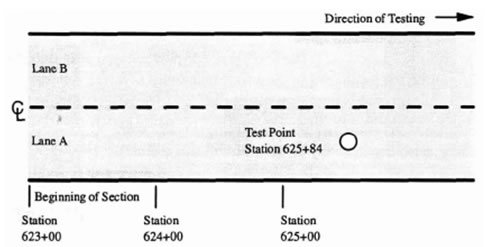
The test location section indicates the number of current test points where "locationcounter" is an integer starting at 1 and ascending for each test point in the current file. Figure 42 provides an example of a typical test location.
Figure 42. Illustration. Example of a typical test location.
Section
Descriptor [Test Location locationcounter]
| Example: | [Test Location 1] |
| Note: | The maximum number for locationcounter is NumberOfTestLocations. This section will be repeated sequentially for each test location. |
Test Location
| Syntax: | GPSLocation = number, number, number |
| Description: | Global location of the test point in an x, y, z coordinate system. |
| Example: | GPSLocation = 28.345, 74.345, 0 |
GPS Location
| Syntax: | GPSLocation = number, number, number |
| Description: | Global location of the test point in an x, y, z coordinate system. |
| Example: | GPSLocation = 28.345, 74.345, 0 |
Test Lane
| Syntax: | TestLane = string |
| Description: | Designation of the lane being tested. Test lane layouts are designated at the discretion of the engineer or FWD operator. |
| Example: | TestLane = outside lane, inner wheelpath |
Test Type
| Syntax: | TestType = string |
| Description: | Type of test being performed (e.g., basin, center, edge, corner). The latter three designations would mainly be used on concrete pavements. |
| Example: | TestType = basin |
Drop History Type
| Syntax: | DropHistoryType = string |
| Description: | The type of drop history recorded at the test location (e.g., load only, deflections only, or load and deflections). |
| Example: | DropHistoryType = load and deflections |
Test Temperatures
| Syntax: | TestTemperatures = number(s) |
| Description: | The temperatures measured for the current test point. |
| Example: | TestTemperatures = 60.7, 94.2, 80.5 |
| Note: | The measured temperatures are described in the [Device Configuration] section (e.g., air, surface, mid-depth, gradient average). |
Test Date
| Syntax: | TestDate = date |
| Description: | Date at onset of testing in dd-mmm-yyyy date format. |
| Example: | TestDate = 12-Apr-2009 |
Test Time
| Syntax: | TestComment = time |
| Description: | Time at the beginning of testing for the current test point in hour:minute:second 24-h clock format. |
| Example: | TestTime = 07:41:18 |
Test Comment
| Syntax: | TestComment = string |
| Description: | Any comment regarding the current test point entered manually by the operator. |
| Example: | TestComment = Longitudinal crack |
Number of Drops
| Syntax: | NumberOfDrops = number |
| Description: | The number of load drops made at each test point. |
| Example: | NumberOfDrops = 12 |
Drop Data
| Syntax: | DropData_dropcounter = number(s) |
| Description: | The measured peak load and deflections for the current drop, where dropcounter is the number of the drop in the sequence. |
| Example: | DropData_l = 9194, 4.93, 4.14, 4.01, 3.65, 3.10, 2.50, 2.15 |
| Note: | The maximum number for dropcounter is NumberOfDrops. |
Drop History Data
| Syntax: | DropHistoryData_dropcounter_samplecounter = number(s) |
| Description: | The time history load and deflections data for each drop, numbered sequentially as dropcounter_samplecounter. Each entry contains information similar in format to DropData_counterdrop when load and deflection are recorded. |
| Example: | DropHistoryData_1_5 = 1248, 1.15, 1.02, 0.98, 0.87, 0.79, 0.70, 0.62 |
| Note: | The maximum number for samplecounter is NumberOfDropHistoryDataSamples |
At the conclusion of each FWD calibration, WinFWDCal creates a permanent electronic record of the calibration results in DDX file format. The file is named FWDCalibrationRecorddd-mmm-yyyy.DDX (where dd is the date, mmm is the month abbreviation, and yyyy is the year (e.g., 12-Feb-2009)).
The file includes the following sections from the PDDX file format as defined above:
The same file is created for both annual and monthly calibration. When retained together with the FWD and reference system data files, a complete record of the calibration is formed that allows the calibration results to be recreated and reviewed at any time using WinFWDCal.
FWD Calibration Center Information Section
This section includes information about the FWD calibration center personnel and equipment. It is created only for record keeping associated with FWD calibration. This section would not normally be included in the PDDX file format that is used for road and airfield data exchange. In order to be self-contained, some additional units of measurement are defined in this file.
Section
Descriptor [FWD Calibration Center Information]
Calibration Center
| Syntax: | CalibrationCenter = string |
| Description: | The name of the FWD calibration center. |
| Example: | CalibrationCenter = Colorado Department of Transportation |
Calibration Center ID Code
| Syntax: | CalCenterIDCode = number |
| Description: | An ID code assigned to each FWD calibration center based upon the order of installation. |
| Example: | CalCenterIDCode = 21 |
Calibration Center Operator
| Syntax: | CalibrationCenterOperator = string |
| Description: | Name of the FWD calibration center operator. |
| Example: | CalibrationCenterOperator = Edward Trujillo |
Calibration Center Operator Certification Date
| Syntax: | CalibrationCenterOperatorCertificationDate = date |
| Description: | Date of last FWD calibration center operator certification and QA/QC visit. The certification is valid for 15 months after this date, and recertification must be scheduled within 12 months of this date. |
| Example: | CalibrationCenterOperator = 27-Aug-08 |
WinFWDCal Version Number
| Syntax: | WinFWDCalVersionNumber = string |
| Description: | Version number of WinFWDCal software along with the release date. |
| Example: | WinFWDCalVersionNumber = 1.2.702 21 April 2008 |
Type of Calibration
| Syntax: | TypeOfCalibration = string |
| Description: | Denotes the type of procedure that was used for the FWD Calibration (e.g., annual, monthly, or sensor replacement). |
| Example: | TypeOfCalibration = Annual |
Signal Conditioner Serial Number
| Syntax: | SignalConditionerSerialNumber = string |
| Description: | Serial number of signal conditioner used in FWD calibration at a calibration center. |
| Example: | SignalConditionerSerialNumber = 095889 |
A to D Board Serial Number
| Syntax: | AtoDBoardSerialNumber = string |
| Description: | Serial number of KUSB A/D board used in FWD calibration at a calibration center. |
| Example: | AtoDBoardSerialNumber = 1142589 |
Universal Test Machine Name
| Syntax: | UniversalTestMachineName = string |
| Description: | Name of universal calibration machine used to calibrate the reference load cell. |
| Example: | UniversalTestMachineName = Baldwin Universal Testing Machine UniversalTestMachineSerialNumber = 040-1663 |
Universal Test Machine Calibration Date
| Syntax: | UniversalTestMachineCalibrationDate = date |
| Description: | Date of NIST traceable calibration of universal testing machine in dd-mmm-yyyy format. |
| Example: | UniversalTestMachineCalibrationDate = 09-Sept-2008 |
Reference Load Cell Name
| Syntax: | ReferenceLoadCellName = string |
| Description: | Name assigned to reference load cell used in FWD calibration. |
| Example: | ReferenceLoadCellName = CLRP001 |
Reference Load Cell Calibration Date
| Syntax: | ReferenceLoadCellCalibrationDate = date |
| Description: | Date of last calibration of reference load cell used in FWD calibration. |
| Example: | ReferenceLoadCellCalibrationDate = 04-August-2004 |
Reference Load Cell Excitation Volts
| Syntax: | ReferenceLoadCellExcitationVolts = number |
| Description: | Excitation value in volts for reference load cell used in FWD calibration. |
| Example: | ReferenceLoadCellExcitationVolts = 10.000 |
Reference Load Cell Signal Conditioner Gain
| Syntax: | ReferenceLoadCellSignalConditionerGain = string |
| Description: | Gain setting on signal conditioner used with reference load cell for FWD calibration. |
| Example: | ReferenceLoadCellGain = 5.3 X 100 |
| Note: | The first number is the setting on the knob of the signal conditioner. It is followed by the gain multiplier (pushbutton). |
Reference Load Cell Unbalanced Zero
| Syntax: | ReferenceLoadCellUnbalancedZero = number |
| Description: | The reading in volts with the load cell in an unbalanced condition. |
| Example: | ReferenceLoadCellUnbalancedZero = 0.283 |
| Note: | By comparing this value to the daily value, the unbalanced zero reading is used to ensure the load cell is undamaged and working properly. |
Reference Load Cell +B Voltage
| Syntax: | ReferenceLoadCell+BVoltage = number |
| Description: | The reading in volts with the load cell balanced first when a shunt resistance is used to produce a positive voltage on the balancing circuit. |
| Example: | ReferenceLoadCell+BVoltage = 1.772 |
| Note: | By comparing this value to the daily value, the +B and -B readings are used to ensure the signal conditioner gain setting is correct. A load cell with a very large gain may need to use the +A and -A shunts on the signal conditioner. In these cases, the field names will have an A instead of a B in the field names. |
Reference Load Cell -B Voltage
| Syntax: | ReferenceLoadCell-BVoltage = number |
| Description: | The reading in volts with the load cell balanced first when a shunt resistance is used to produce a negative voltage on the balancing circuit. |
| Example: | ReferenceLoadCell-BVoltage = -1.772 |
| Note: | By comparing this value to the daily value, the +B and -B readings are used to ensure the signal conditioner gain setting is correct. A load cell with a very large gain may need to use the +A and -A shunts on the signal conditioner. In these cases, the field names will have an A instead of a B in the field names. |
Reference Load Cell Calibration Units
| Syntax: | ReferenceLoadCellCalibrationUnits = string |
| Description: | The units used in the calibration of the reference load cell (kiloNewton or pound-force). |
| Example: | ReferenceLoadCellCalibrationUnits = pound-force |
Reference Load Cell Calibration Coefficients
| Syntax: | ReferenceLoadCellCalibrationCoefficients = number(s) |
| Description: | Polynomial coefficients used to convert volts into load in units listed under ReferenceLoadCellCalibrationUnits. |
| Example: | ReferenceLoadCellCalibrationCoefficients = -98.2421e-01, 27.1714e-05, 61.1421e-09, 00.0000e+00, 00.0000e+00 |
Reference Load Cell Trigger Level
| Syntax: | ReferenceLoadCellTriggerLevel = number |
| Description: | The load level in ReferenceLoadCellCalibrationUnits that is used to start auto-triggering and collection of data during FWD calibration. |
| Example: | ReferenceLoadCellTriggerLevel = 1,000 |
Reference Load Cell Daily Unbalanced Zero
| Syntax: | ReferenceLoadCellDailyUnbalancedZero = number |
| Description: | The daily reading in volts with the load cell in an unbalanced condition taken as part of the prerequisites of calibration. |
| Example: | ReferenceLoadCellDailyUnbalancedZero = 0.283 |
| Note: | The unbalanced zero reading is used to ensure the load cell is undamaged and working properly. |
Reference Load Cell Daily +B Voltage
| Syntax: | ReferenceLoadCellDailyPBVoltage = number |
| Description: | The daily +B voltage reading taken as part of the prerequisites of calibration. Together with the -B reading, these data are used to account for variations in the setting of the gain by the FWD calibration center operator. |
| Example: | ReferenceLoadCellDailyPBVoltage = 1.773 |
Reference Load Cell Daily -B Voltage
| Syntax: | ReferenceLoadCellDailyMBVoltage = number |
| Description: | The daily -B voltage reading taken as part of the prerequisites of calibration. Together with the +B reading, these data are used to account for variations in the setting of the gain by the FWD calibration center operator. |
| Example: | ReferenceLoadCellDailyMBVoltage = -1.773 |
Accelerometer Model Number
| Syntax: | AccelerometerModelNumber = string |
| Description: | Manufacturer’s model number of accelerometer used in FWD deflection sensor calibration. |
| Example: | AccelerometerModelNumber = 2220-005 |
Accelerometer Serial Number
| Syntax: | AccelerometerSerialNumber = string |
| Description: | Manufacturer’s serial number of accelerometer used in FWD deflection sensor calibration. |
| Example: | AccelerometerSerialNumber = 278 |
Accelerometer Reference Calibration Date
| Syntax: | AccelReferenceCalibrationDate = date |
| Description: | Date of calibration of reference accelerometer provided by manufacturer. |
| Example: | AccelReferenceCalibrationDate = 07-Sep-2004 |
Accelerometer Reference +1G DC
| Syntax: | AccelRef+1GDC = number |
| Description: | Reading of accelerometer in a +1G field (volts) provided by manufacturer. |
| Example: | AccelRef+1GDC = 0.825 |
Accelerometer Reference -1G DC
| Syntax: | AccelRef-1GDC = number |
| Description: | Reading of accelerometer in a -1G field (volts) provided by manufacturer. |
| Example: | AccelerometerRef-1GDC = -0.777 |
Accelerometer Reference Calibration Coefficients
| Syntax: | AccelRefCalibrationCoefficients = number(s) |
| Description: | Polynomial coefficients to convert output in volts into acceleration in g provided by manufacturer where the first coefficient listed is co. |
| Example: | AccelRefCalibrationCoefficients = -4.52e-02, 1.241e + 00, 1.048e-03, -1.369e-04 |
| Notes: | The form of the equation is acceleration (g) = co + ∑ (ci volts). |
Accelerometer Daily Calibration Date
| Syntax: | AccelDailyCalibrationDate = date |
| Description: | Date of the last daily flip calibration in dd-mmm-yyyy format. |
| Example: | AccelDailyCalibrationDate = 03-Aug-2005 |
Accelerometer Daily Calibration Time
| Syntax: | AccelDailyCalibrationTime = time |
| Description: | The time of the last daily flip calibration of the accelerometer in hour:minute 24-h clock format. |
| Example: | AccelDailyCalibrationTime = 16:17 |
Accelerometer Daily Calibration Temperature Unit
| Syntax: | AccelDailyCalibrationTemperatureUnit = string |
| Description: | Units of temperature used when performing the last daily flip calibration of the accelerometer (Fahrenheit or Celsius). |
| Example: | AccelDailyCalibrationTemperatureUnit = Fahrenheit |
Accelerometer Daily Calibration Temp
| Syntax: | AccelDailyCalibrationTemp = number |
| Description: | Temperature recorded during the last daily flip calibration of the accelerometer in units of AccelDailyCalibrationTemperatureUnit. |
| Example: | AccelDailyCalibrationTemp = 67.5 |
Accelerometer Excitation Volts
| Syntax: | AccelExcitationVolts = number |
| Description: | Excitation voltage for the reference accelerometer. |
| Example: | AccelExcitationVolts = 10 |
Accelerometer Signal Conditioner Gain
| Syntax: | AccelSignalConditionerGain = string |
| Description: | Gain setting on signal conditioner used with for the reference accelerometer. |
| Example: | AccelSignalConditionerGain = 2.0 X 1 |
| Note: | The first number is the setting on the knob of the signal conditioner. It is followed by the gain multiplier (pushbutton). |
Accelerometer Daily Slope Factor
| Syntax: | AccelDailySlopeFactor = number |
| Description: | Calculated relative difference in voltage between the reference calibration and the last daily flip calibrations. |
| Example: | AccelDailySlopeFactor = -0.50486 |
| Note: | This value is multiplied by the output voltage to generate a relative voltage that can be used directly with the calibration factors from the accelerometer certificate (AccelerometerRefCalibrationCoefficients). |
Accelerometer Historical Slope Factor Dates
| Syntax: | AccelHistoricalSlopeFactor = date, date, date, date |
| Description: | Dates of the four accelerometer historical slope factors in dd-mmm-yyyy format. |
| Example: | AccelHistoricalSlopeFactorDates = 12-Jan-2009, 02-Feb-2009, 27-Feb-2009, 18-Mar-2009 |
Accelerometer Historical Slope Factors
| Syntax: | AccelHistoricalSlopeFactor = number, number, number, number |
| Description: | Historical listing of the previous four accelerometer slope factors. |
| Example: | AccelHistoricalSlopeFactor = -0 49856, -0 49857, -0 49853, -0 49850 |
| Note: | These values are compared to the accelerometer daily slope factor during the FWD calibration to ensure the device is working properly. |
Accelerometer Daily Calibration +1G Voltage
| Syntax: | AccelDailyCalibration+1GVoltage = number |
| Description: | Recorded voltage in a +1-G field during the last flip calibration of the accelerometer. |
| Example: | AccelDailyCalibration+1GVoltage = 1.7598 |
Accelerometer Daily Calibration -1G Voltage
| Syntax: | AccelDailyCalibration-1GVoltage = number |
| Description: | Recorded voltage in a -1-G field during the last flip calibration of the accelerometer. |
| Example: | AccelDailyCalibration-1GVoltage = -1.7598 |
Accelerometer Daily Calibration +1G Flip Voltage
| Syntax: | AccelDailyCalibration+1GFlipVoltage = number |
| Description: | Recorded voltage in a +1-G field after the -1 g reading during the last flip calibration of the accelerometer. |
| Example: | AccelDailyCalibration+1GFlipVoltage = 1.7698 |
| Note: | The daily calibration readings are used to confirm that the hysteresis of the accelerometer is not significant and will not adversely affect the FWD calibration. |
Accelerometer Trigger Level
| Syntax: | AccelTriggerLevel = number |
| Description: | The acceleration level in g units that is used to start auto-triggering and collection of data during FWD calibration. |
| Example: | AccelTriggerLevel = 0.50 |
The information in this section will assist FWD manufacturers to adapt their FWD operating systems (field programs) to be more compatible with the FWD annual and monthly calibration processes. This section defines the format for a minimum subset of the many data items listed in the previous sections that is needed to facilitate calibration.
Electronic methods are used to transfer data between the FWD computer and the calibration computer. Some of this information is required just for record-keeping purposes, while other data items are used in the calibration calculations. Electronic data transfer helps reduce transcription errors and expedite FWD calibration.
At the beginning of a calibration, the FWD computer needs to provide some information about the load cell, deflection sensor serial numbers, the current gain factors, the FWD operator’s name, etc. The FWD operating program (field program) should be able to produce a file named FWDCalibrationInput dd-mmm-yyyy.DDX (where dd is the date, mmm is the month abbreviation, and yyyy is the year (e.g., 12-Nov-2009)). The contents of this file are defined below.
After an annual or monthly calibration is complete, the FWD operating program needs to be able to locate and read the results from a file named FWDCalibrationOutputdd-mmm-yyyy.DDX. The results should then be used to update the calibration data in the FWD computer.
Input Data Requirements for WinFWDCal
The following is an example of the contents of FWDCalibrationInput dd-mmm-yyyy.DDX. Only the data sections and data items are listed here. A complete description of each item is provided in the previous sections.
[Pavement Deflection Data Exchange File]
PDDXVersionNumber = 2.0
DelimiterSymbol = ,
DecimalSymbol = .
[Operations Information]
FileName =D:\WINFWD\Temp\FWDCalibrationInput 20-Feb-2009.ddx
EndDate = 02-20-2009
EndTime = 15:43
OperatorName = Daniel Atkins
[Units]
LoadUnits = pound
DeflectionUnits = mil
[Device Information]
DeviceDesignationName = Dynatest® FWD
DeviceModelNumber = 8001
DeviceSerialNumber = 8001-001
LoadCellSerialNumber = 0331
SensorSerialNumbers = 3170, 3162, 3163, 3164, 3165, 3166, 3167, 3168, 3169
[Device Configuration]
NumberOfDeflectionSensors = 9
[Device Calibration]
LoadCellAnnualCalibrationDate = 20-Feb-2008
LoadCellAnnualCalibrationGain = 1.0006
SensorAnnualCalibrationDate = 20-Feb-2008
SensorCalibrationGains = 1.001, 0.999, 1.001, 0.999, 0.999, 0.998, 1, 0.996, 0.999
The following is an example of the contents of FWDCalibrationOutput dd-mmm-yyyy.DDX. Only the data sections and data items are listed. A complete description of each item is provided in the previous sections.
[Pavement Deflection Data Exchange File]
PDDXVersionNumber = 1.0
DelimiterSymbol = ,
DecimalSymbol = .
[Operations Information]
FileName = C:\WinFWDCal\InterimDropData\FWDCalibrationOutput 21-Feb-2009.ddx
EndDate = 21-Feb-2009
EndTime = 15:43
OperatorName = Daniel Atkins
[Device Information]
DeviceDesignationName = Dynatest® FWD
DeviceModelNumber = 8001
DeviceSerialNumber = 8001-001
LoadCellSerialNumber = 0331
SensorSerialNumbers = 3170, 3162, 3163, 3164, 3165, 3166, 3167, 3168, 3169
[Device Configuration]
NumberOfDeflectionSensors = 9
[Device Calibration]
LoadCellAnnualCalibrationDate = 21-Feb-2009
LoadCellAnnualCalibrationGain = 1.0005
SensorAnnualCalibrationDate = 21-Feb-2009
SensorCalibrationGains = 1.002, 1.002, 1.003, 1.000, 1.000, 0.999, 1.002, 0.997, 1.001
[FWD Calibration Center Information]
CalibrationCenter = Cornell Local Roads
CalCenterIDCode = 21
CalibrationCenterOperator = David Orr
CalibrationCenterOperatorCertificationDate = 18-Nov-2008
WinFWDCalVersionNumber = Version 1.4.18 22 December 2008
TypeOfCalibration = Annual