U.S. Department of Transportation
Federal Highway Administration
1200 New Jersey Avenue, SE
Washington, DC 20590
202-366-4000
Federal Highway Administration Research and Technology
Coordinating, Developing, and Delivering Highway Transportation Innovations
 |
| This report is an archived publication and may contain dated technical, contact, and link information |
|
Publication Number: FHWA-HRT-07-052 Date: September 2007 |
The pressure chamber is used to contain the test specimen and the confining fluid during the test. A typical triaxial chamber suitable for use in resilient testing of soils is shown in Figure 4. The deformation is measured externally with two spring-loaded LVDTs as shown in Figure 4.
6.1.1 Air shall be used in the triaxial chamber as the confining fluid for all LTPP testing.
6.1.2 The chamber shall be made of Lexan, Acrylic or other suitable "see-through" material to facilitate the observation of the specimen during testing.
The loading device shall be a top loading, closed loop electrohydraulic testing machine with a function generator which is capable of applying repeated cycles of a haversine-shaped load pulse nominally 0.1 second in duration; followed by rest periods of nominally 0.9 second duration.
The haversine shaped load pulse shall conform to definition (k), Section 3 of this protocol. All preconditioning and testing shall be conducted using a haversine-shaped load pulse. The system generated haversine waveform and the response waveform shall be displayed to allow the operator to adjust the gains to ensure that they coincide during preconditioning and testing.
6.3 Load and Specimen Response Measuring Equipment
6.3.1 The axial load measuring device should be an electronic load cell located between the actuator and the chamber piston rod as shown in Figure 4. The following load cell capacities are required:
| Sample Diameter | Maximum Load Capacity | Required Accuracy |
| mm(inches) | kN (lbs) | N (lbs) |
| 71 (2.8) | 2.2 (500) | ± 4.5 (± 1) |
| 152 (6.0) | 22.24 (5000) | ± 22.24 (± 5) |
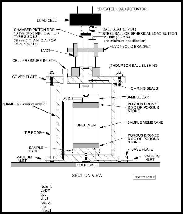
Figure 4. Typical triaxial chamber with external LVDTs and load cell.
NOTE 4: During periods of resilient modulus testing, the load cell shall be monitored and checked once every two weeks or after every 50 resilient modulus tests with a calibrated proving ring to assure that the load cell is operating properly. An alternative to using a proving ring is to insert an additional calibrated load cell and independently measure the load applied by the original load cell to ensure accurate loadings. Additionally, the load cell shall be checked at any time that the laboratory's in-house QC/QA testing indicates non-compliance or there is a suspicion of a load cell problem. Resilient modulus testing shall not be conducted if the testing system is found to be out of calibration or if the load cell does not meet the manufacturer's tolerance requirements or the tolerance requirements stated above for accuracy, whichever of the two is of the higher accuracy. In addition, all requirements regarding the load cell contained in the Start-up and QC Procedure for LTPP P46 Resilient Modulus Testing must be adhered to at all times.
Previous | Table of Contents | Back to FHWA-RD-07-052 | Next

