U.S. Department of Transportation
Federal Highway Administration
1200 New Jersey Avenue, SE
Washington, DC 20590
202-366-4000
Federal Highway Administration Research and Technology
Coordinating, Developing, and Delivering Highway Transportation Innovations
 |
| This report is an archived publication and may contain dated technical, contact, and link information |
|
Publication Number: FHWA-RD-07-052 Date: September 2007 |
This protocol covers the test method for the determination of the shear strength at the interface of bonded layers of concrete. This protocol is based on the Iowa DOT Test Method No. IOWA 406-B (September 1984). The test described herein shall be performed on drilled concrete cores obtained from LTPP test sections as shown on the materials testing plans developed for each project.
1.1 General
This test method covers the determination of the interface shear strength of a drilled concrete core sampled from a bonded concrete overlay pavement.
1.2 Summary of Test Method
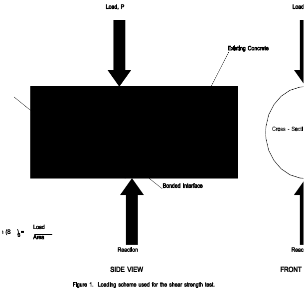
This method consists of applying a continuous load to the vertical diametral plane of the test specimen along the bonded interface between the overlay concrete and existing concrete (see Figure 1). The load is applied until a shear failure occurs at the bonded interface. The bond shear strength is calculated by dividing the maximum load attained during the test by the cross-sectional area of the test specimen.
1.3 Significance and Use The bond shear strength may be used to assess the integrity of the bond between bonded concrete overlay and the underlying concrete pavement.
1.4 Sample Storage PCC cores shall be stored flat side down, fully supported and at between 5 ° C (40 ° F) and 38 ° C (100 ° F) in an environmentally protected (enclosed area not subject to the natural elements) storeroom. Each specimen shall have a label or tag attached that clearly identifies the material, the project number/test section from which it was recovered, and the sample number, as a minimum.
1.5 Units
In this protocol, the International System of Units (SI - The Modernized Metric System) is regarded as the standard. Units are expressed first in their "soft" metric form followed, in parenthesis, by their U.S. Customary unit equivalent.

2.1 Testing Prerequisites
The testing described in this protocol shall be conducted after; (1) approval by the FHWA COTR to begin testing, (2) initial layer assignment using Form L04, (3) visual examination and thickness of PCC cores and thickness of layers within PCC cores using Protocol P66, (4) final layer assignment based on the P66 test results (corrected Form L04 if needed), and (5) completion of all other applicable tests. In order to obtain approval under item (1), the laboratory must, at least, (a) submit and obtain approval of the QC/QA plan for FHWA materials testing, and (b) demonstrate that their testing equipment meets or exceeds the specifications contained in this protocol.
2.2 Test Sample Locations and Assignment of Laboratory Test Numbers
The test shall be performed on the test specimens of PCC retrieved from C-type, 102-mm (4-inch) diameter coreholes or from other sampling locations as dictated by the sampling plans for the particular LTPP section.
The test results shall be reported separately for test specimens obtained from the beginning and end of a test section as follows:
The following definitions will be used throughout this protocol.
4.1 ASTM Standards C39 Standard Test Method for Compressive Strength of Cylindrical Concrete Specimens
C42 Standard Test Method for Obtaining and Testing Drilled Cores and Sawed Beams of Concrete
E4 Standard Practices for Load Verification of Testing Machines
E74 Standard Practices for Calibration of Force-Measuring Instruments for Verifying the Load Indication of Testing Machines
4.2 AASHTO Standards T24 Standard Method of Obtaining and Testing Drilled Cores and Sawed Beams of Concrete
T67 Standard Methods of Load Verification of Testing Machines
4.3 LTPP Protocols P66 Visual Examination and Thickness of Portland Cement Concrete Cores
4.4 Other Documents: Iowa Test Method No. 406-B, Method of Test for Determining the Shearing Strength of Bonded Concrete, Iowa DOT, 1984
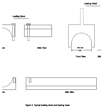
5.1 Loading Block The loading block used for the bond shear test shall be designed to accommodate a 102-mm (4-in.) diameter test specimen. A typical loading block is illustrated in Figure 2.
5.2 Loading Head A metal loading head with a concave surface having a 51-mm (2-in.) radius of curvature is required to apply load to the specimen. The loading head shall be 13 mm (0.5 in) wide. Edges should be rounded by grinding to remove sharp edges. A typical loading head is illustrated in Figure 2.
5.3 Testing Machine
The testing machine shall conform to the requirements of the ASTM Test Method C 39 possessing sufficient capacity that will provide the rate of loading described in Section 7.

6.1 Test specimens shall consist of drilled, 102-mm (4-in) diameter cores sampled from the test section. The cores shall be drilled in accordance with the procedures set forth in the LTPP Guide for Field Materials Sampling Testing and Handling. The length of the drilled cores shall include both the existing and the overlay concrete layers.
7.1 Specimen Positioning
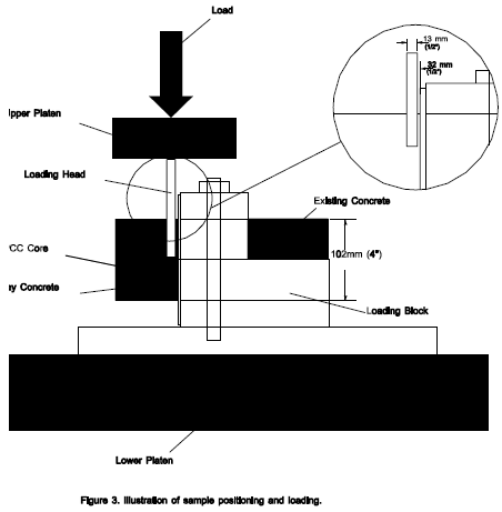
7.1.1 Secure the specimen in the loading block. The bonded interface shall be centered between the edge of the loading block and the edge of the loading head.
7.1.2 Align the loading head adjacent to the bonded interface. The loading head shall rest parallel to the bonded interface on the overlay concrete portion of the specimen.
NOTE 1 : Sample positioning and loading is shown in Figure 3.
7.2 Rate of loading
7.2.1 Apply the load continuously and without shock, at a constant rate within the range of 2760 to 3450 kPa (400 to 500 psi) per minute until failure occurs. Record the maximum applied load, PMAX, carried by the specimen during the test.
8.1 Calculate the bond shear strength, SB, as follows:

where: SB = bond shear strength, kPa
PMAX = maximum load applied to specimen, N
A = cross-sectional area of test specimen, mm2
and:

where: A = cross-sectional area of test specimen, mm2
D = diameter of test specimen, mm

The following information shall be recorded on Form T67.
9.1 Sample identification shall include: Laboratory Identification Code, State Code, SHRP ID, Layer Number, Field Set Number, Sampling Area No., Sample Location Number, and LTPP Sample Number.
9.2 Test identification shall include: LTPP Test Designation, LTPP Protocol Number, Laboratory Test Number and the Test Date.
9.3 Failure Plane. Identify if failure occurred at the interface, in the existing concrete layer, or in the overlay concrete.
9.4 Test Results
9.4.1 Specimen dimensions including thickness of the overlay concrete, thickness of existing concrete, diameter and cross-sectional area.
9.4.2 Maximum load applied in N.
9.4.3 Bond shear strength in kPa.
9.5 Comments shall include LTPP standard comment codes, as shown in Section 4.3 of this Guide and any other notes as needed. Additional codes for special comments associated with the shear bond strength test are given below:
| Code | Comment |
|---|---|
| 53 | Irregular interface between existing and overlay concrete. |
| 54 | Failure plane in overlay concrete. |
| 55 | Failure plane in existing concrete. |
| 56 | Failure plane in interface between existing and overlay concrete. |
LTPP LABORATORY MATERIAL HANDLING AND TESTING
LABORATORY MATERIAL TEST DATA
DETERMINATION OF THE SHEAR STRENGTH AT THE INTERFACE OF BONDED LAYERS OF CONCRETE
LAB DATA SHEET T67
PORTLAND CEMENT CONCRETE
LTPP TEST DESIGNATION PC07/LTPP PROTOCOL P67
LABORATORY PERFORMING TEST: _____________________________________________________________
LABORATORY IDENTIFICATION CODE: ___ ___ ___ ___
REGION: _________________________ STATE: STATE CODE: __ __
EXPERIMENT NO: _____ SHRP ID: __ __ __ __
SAMPLED BY: _________________________________________ FIELD SET NO: ___
DATE SAMPLED: __ __ - __ __ - __ __ __ __ SAMPLING AREA NO: SA- ____
1. LAYER NUMBER (OVERLAY LAYER) __
2. LAYER NUMBER (ORIGINAL SURFACE LAYER) __
3. LOCATION NUMBER __ __ __
4. LABORATORY TEST NUMBER __
5. LTPP SAMPLE NUMBER __ __ __ __
6. DIAMETER, mm.
7. LENGTH OF SPECIMEN, mm.
8. THICKNESS OF OVERLAY LAYER, mm.
9. THICKNESS OF ORIGINAL SURFACE LAYER, mm.
10. CROSS-SECTIONAL AREA, mm2.
11. MAXIMUM LOAD, N.
12. SHEAR BOND STRENGTH, kPa.
13. COMMENTS
(a) CODE
(b) NOTE
TEST DATE __ __ - __ __ - __ __ __ __
| GENERAL REMARKS:___________________________________________________________________________ | |
| SUBMITTED BY, DATE | CHECKED AND APPROVED, DATE |
| ______________________________ | ______________________________ |
| LABORATORY CHIEF Affiliation______________________ | Affiliation______________________ |
| << Previous | Contents | Next >> |