U.S. Department of Transportation
Federal Highway Administration
1200 New Jersey Avenue, SE
Washington, DC 20590
202-366-4000
Federal Highway Administration Research and Technology
Coordinating, Developing, and Delivering Highway Transportation Innovations
 |
| This report is an archived publication and may contain dated technical, contact, and link information |
|
Publication Number: FHWA-RD-03-031 Date: JUNE 2003 |
|
TABLE
OF CONTENTS
|
|
Measurement of Faulting in the LTPP Program |
This manual is intended for use by the FHWA-LTPP Regional Coordination Office personnel and others responsible for using the faultmeter to measure JCP faulting, and for measuring lane-to-shoulder dropoff on LTPP pavement test sites.
The change in joint faulting and lane-to-shoulder dropoff with time are important indicators of pavement performance. The digital faultmeters will be used to collect this data. It is the responsibility of each regional coordination office contractor to store, maintain, and operate their faultmeter for faulting and lane-to-shoulder dropoff data collection.
The electronic digital faultmeter was designed to simplify measuring concrete joint faulting. This meter was designed, developed and built by the Georgia Department of Transportation Office of Materials and Research personnel 1. The faultmeter is very light and easy to use. The unit, shown in figure 1, weighs approximately 3.2 kg and supplies a digital readout with the push of a button located on the carrying handle. It reads out directly in millimeters (e.g., a digital readout of "6" indicates 6 mm of faulting) and shows whether the reading is positive or negative. The unit reads out in 1 second and freezes the reading in display so that it can be removed from the road before reading for safer operation. The legs of the faultmeter's base are set on the slab in the direction of traffic on the "leave side" of the joint. The measuring probe contacts the slab on the approach. Movement of this probe is transmitted to a Linear Variance Displacement Transducer to measure joint faulting. The joint must be centered between the guidelines shown on the side of the meter.
Any slab that is lower on the leave side of the joint will register as a positive faulting number. If the slab leaving the joint is higher, the meter gives a negative reading.
The amount of time it takes to complete the faulting survey of a LTPP test section depends on the number of joints and cracks encountered, and on the amount of time needed to measure and record the location of each joint and crack. Generally, it should take less than 30 minutes to measure and record faulting and lane-to-shoulder dropoff on a 150-m test section using this device.
The Mechanical Faultmeter
The mechanical faultmeter was designed as a backup to the Georgia Faultmeter. It is not intended for use as a primary measuring device for faulting. The mechanical faultmeter has the same "footprint" as the Georgia Faultmeter and should be used in a similar manner. It has a dial indicator instead of the Georgia Faultmeter's electronic digital readout. The mechanical faultmeter also does not take negative faulting readings, and must be reversed to read negative faulting.
This section gives step-by-step operating instructions. The Georgia Faultmeter has several unique features, which have been added to simplify operations, increase range of measurement to 22 mm, and increase reach to 100 mm to allow for spanning spalls and excess joint material on the slab surface.
Use the right hand when testing the outside lane. This allows the operator to stand safely on the shoulder, facing traffic, while making the test. There is an arrow on the meter showing traffic direction. Set the meter on the leave side of the joint. A probe contacts the slab on the approach side. The joint must be centered approximately between the two marks on each side of the meter.
As indicated in Chapter 3 of the Data Collection Guide2, faulting of transverse joints and cracks is measured as the difference in elevation to the nearest 1 mm between the pavement surface on either side of a transverse joint or crack. In cases of a widened lane, measure 0.3 m from the edge of the slab and 0.75 m from the outside edge of the lane edge stripe. When anomalies such as patching, spalling, and corner breaks are encountered, the faultmeter should be offset to avoid including such anomalies in the readings. The maximum offset is 0.3 m. A null value ("N") should be recorded and entered into the database when the surveyor is unable to take a measurement due to an anomaly.
Three measurements are made at each location. The representative value of the readings is recorded to the nearest millimeter. Measurements are taken at every joint and crack. This data is to be recorded on distress survey sheet 6. The distance from the start of the test section to the point where the measurement is taken is also recorded. This distance is obtained with a metric tape measure. Faulting is assumed to be positive. Therefore, the space to the left of the entry of measured faulting is to be filled with a negative sign when necessary. If the approach slab is higher than the departure slab, no positive sign is to be entered. If the approach slab is lower, a negative sign is entered. The readings recorded on the faultmeter are reported in millimeters on sheet 6. Faulting measurements and sheet 6 are to be completed at the beginning of the distress survey. Point distance measurements entered on sheet 6 for joints and transverse cracks should be consistent between surveys of the same test section to an accuracy of less than 0.5 m. Evaluate point distance differences for previous measurements of ³ 0.5 m with a metric tape measure. NOTE: The precise start point of surveys must be identified clearly in the field.
Lane-to-shoulder dropoff is measured as the difference in elevation to the nearest 1 mm between the pavement surface and the adjacent shoulder surface. Measurements are taken at the beginning of the test section and at 15.25 m intervals (a total of 11 measurements) at the lane/shoulder interface or joint. Lane-to-shoulder dropoff typically occurs when the outside shoulder settles. However, heave of the shoulder may occur due to frost action or swelling soil. If heave of the shoulder is present, record it as a negative value. At each point where there is no lane-to-shoulder dropoff, enter "0." This data should be entered again on JCP data sheet 7 and CRCP data sheet 10.
The distance from the center of the measuring probe to the edge of the base's forward foot is 100 mm to allow easy placement on the joint, and for more overhang, to measure shoulder dropoff. In addition, the base feet are 50 mm long, to bridge any bad crack or low spot in the pavement. The faultmeters will read up to 22 mm. Differential elevations greater than 22 mm will still need to be measured using the machined spacer block supplied with the faultmeter.
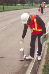
FIGURE B1
The Georgia Faultmeter in Use
The operational procedures for the mechanical faultmeter are the same as for the Georgia Faultmeter, with the exception of taking negative faulting readings. The mechanical faultmeter must be reversed to record negative readings and lane-to-shoulder dropoff.
Surveyors must ensure that they have a working faultmeter with fully charged batteries prior to beginning a survey on a test section. Although the meter is very stable, it should be checked at the beginning and end of every use to assure correct readings. Calibration is checked by setting the meter on the calibration stand, which has been provided with the faultmeter. Align the front end of the faultmeter with the measuring probe on the 9-mm calibration block. In this position, a reading of 9 mm should be obtained. Then align the meter should with the measuring probe off the 9-mm calibration block. In this position, reading of 0 mm should be obtained.
As long as the "0" and "9" readings are obtained, the unit is working properly. If not, align the meter with the measuring probe off the 9-mm calibration block. In this position, if a reading of 0 mm is not obtained, reset the "0" with the "0" button and check the calibration again. Be sure to check for any electronic malfunction before checking the calibration. Weak batteries can also cause an erroneous reading.
Faultmeters that do not pass the calibration checks, or cannot be "zeroed" or have other maintenance problems, should be returned to FHWA's LTPP team distress coordinator for repair.
The calibration checks are the same for the mechanical faultmeter. "Zero" adjustments can be made to the mechanical faultmeter with a one-eighth-inch allen wrench by adjusting the dial indicator height with the set screw adjacent to the dial indicator. Care must be taken during adjustment to ensure that the measuring rod moves freely.
The only maintenance normally required for the faultmeter is the routine recharging of the batteries. When the batteries no longer hold a charge, they should be replaced. The meter should be sent to FHWA's LTPP team for repairs, maintenance, and battery replacement.
The mechanical faultmeter requires no special maintenance.
If the measuring rod does not move freely, the readings will be in error. This should not be a problem, as the rod is made of stainless steel and will not rust. If the rod becomes coated with road film and dust, clean it with a damp cloth. Do not clean with penetrating oil or any products that will leave an oily residue, as this will cause dust to adhere to the rod. If the rod "clicks" when the meter is lifted from the pavement, this is a good indication that it is sliding freely.

