U.S. Department of Transportation
Federal Highway Administration
1200 New Jersey Avenue, SE
Washington, DC 20590
202-366-4000
Federal Highway Administration Research and Technology
Coordinating, Developing, and Delivering Highway Transportation Innovations
 |
| This report is an archived publication and may contain dated technical, contact, and link information |
|
Publication Number: FHWA-RD-01-163 Date: March 2002 |
Previous | Table of Contents | Next
In order to assess the guidelines developed under this project, in-service concrete pavements exhibiting MRD were subjected to a coordinated series of field testing and laboratory evaluation activities. In this way, the usefulness and applicability of the guidelines could be evaluated under actual field conditions, thereby providing feedback on what areas of the guidelines worked well and what areas required modification or refinement.
This chapter briefly describes the field and laboratory testing activities that were conducted under this project. First, a discussion of the pavement project selection process is provided, including a listing of the six pavement projects selected for inclusion in the study. Next, a general summary of the data collection and analysis process is provided. Finally, a summary of the improvements to the guidelines that came out of the field and laboratory testing (and incorporated into the final version of the guidelines) is provided. Bound separately in Volume 3 of this Final Report are the individual case studies that include the condition survey, field sampling, and laboratory analysis results obtained for each of the projects, leading up to the identification of the most likely MRD type present in the pavement.
The goal of the project selection process was to identify candidate concrete pavement projects suffering from MRD so that the guidelines could be tested under "real-world" conditions. The project team asked members of the advisory panel as well as representatives from other highway agencies to submit candidate projects so that a significant number of potential projects would be available. Ideally, the candidate project will be exhibiting a heretofore unidentified distress so the ability of the guidelines to diagnose the distress could be evaluated. However, some level of diagnostic work had been conducted on several of the candidate projects.
The project team reviewed the list of candidate projects and prioritized the list based on the desire to have a range of MRD types included in the study and the need to have at least one suitable project in each of the four SHRP LTPP climatic regions (Wet-Freeze, Wet-Nonfreeze, Dry-Freeze, Dry-Nonfreeze). Although a total of four projects was originally specified for the evaluation of the guidelines, the project team decided to include some additional projects in order to provide a more complete assessment of the guidelines. To incorporate these additional projects without adversely affecting the budgetary limitations of the project, two sets of test sites were established:
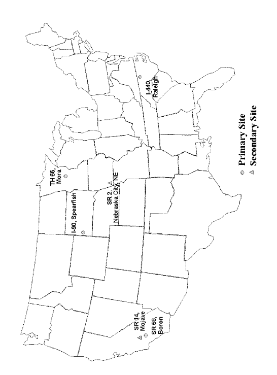
The primary and secondary test sites included in the study are listed in table 1-12. Again, the primary test sites represent each of the four SHRP LTPP climatic regions, and also include a range of other factors including age, pavement design, and type of distress manifestation. The secondary sites are included to provide additional sections for assessing the guidelines. The general location of these projects is shown in figure 1-11.
Table 1-12. Primary and secondary test sites included in study.
State |
Highway/City |
Climatic |
Pavement |
Year |
Primary Sites |
||||
California |
SR 58, Boron |
Dry-Nonfreeze |
230 mm JPCP |
1971 |
Minnesota |
TH 65, Mora |
Wet-Freeze |
200 mm JPCP |
1989 |
North Carolina |
I-440, Raleigh |
Wet-Nonfreeze |
200 mm JPCP |
1982 |
South Dakota |
I-90, Spearfish |
Dry-Freeze |
200 mm JRCP |
1968 |
Secondary Sites |
||||
California |
SR 14, Mojave |
Dry-Nonfreeze |
215 mm JPCP |
1972 |
Iowa |
SR 2, Nebraska City |
Wet-Freeze |
240 mm JPCP |
1986 |
The pavement projects included in the study were subjected to a detailed field condition survey, and core samples were retrieved from prescribed locations for laboratory testing and evaluation. All of these activities were performed in accordance with the systematic procedures outlined in the guidelines presented in Volume 2 of this Final Report. This section briefly describes the field and laboratory testing activities that were conducted on the projects.
 |
 |
Field Distress Data Collection
Preliminary Records Review
Prior to conducting the field evaluations, the project team solicited general design and construction information from the participating highway agencies for each pavement project. This included general location data, basic structural design data, specific mix design information, and traffic data. The limits of the project were defined as that length of pavement over which the structural design, date and method of construction, and paving and foundation materials are the same.
Survey Preparation
The project team made several preparations prior to the conduct of the field surveys in order to ensure that they proceeded as smoothly and efficiently as possible. These preparations included:
In addition, each project was assigned a unique project identifier, using the following naming convention:
[State]-[Highway Number]-[Beginning Milepost]-[Section Number]
where:
State = Two-letter state abbreviation (e.g., MN, IA).
Highway Number = Three-digit highway number (e.g., 015, 440).
Beginning Milepost = Three-digit number of lowest milepost of project limits (e.g., 220, 059).
Section Number = Three-digit number of section within the project (e.g., 001, 002).
Shoulder Survey
Prior setting up the traffic control and conducting the pavement distress surveys, the project team first drove the limits of the project to assess the overall pavement condition and the uniformity of distress levels, topography, and traffic volumes. In addition, candidate sections of the project for the field investigation were noted based on distress uniformity and traffic control and safety considerations.
During the shoulder survey, the project team drove along the shoulder at slow speeds (8 to 16 km/h) and noted the general pavement conditions by milepost or by distance as measured from the beginning of the project with the vehicle’s odometer. In addition, any prevailing roadway characteristics that might have an effect on the performance of the pavement (e.g., areas of cuts/fills, topography, traffic volume/loading) were noted. These shoulder surveys were conducted in both directions to determine if any directional differences in performance or distress manifestations were apparent.
Section Layout
After the shoulder survey was conducted, the pavement sections to be included in the field surveys were selected. Generally, either one or two sections were selected within each project in accordance with the guidelines.
Once the section was selected and the traffic control established, a nominal length of 150 m was used in laying out the pavement sections to ensure consistency with the LTPP program. The actual section length depended on the joint spacing, but a minimum length of 150 m was always obtained for each section.
The section was laid out by selecting a beginning point (usually right at a milepost, station number, or other permanent marker or fixture to facilitate locating the sample unit in the future) and marking with paint the beginning of the section at the transverse joint nearest the marker. The beginning point was noted with a line and with a station number of "0+00" by defining this starting location as station 0+00, all stationing along the section was made relative to the beginning point.
Once the beginning point was established, a distance of 150 m was wheeled off in the direction of traffic to the end of the section. The end of the sample unit was marked at the far end of the slab in which the 150-m mark was encountered. While the sample unit length was being measured, additional marks and station numbers were made at 15-m intervals (e.g., 0+15, 0+30, 0+45, and so on) to aid in conducting the distress surveys. This stationing was also useful in noting the locations of samples retrieved, photos taken, and any other testing performed within the section.
Also during the section layout, members of the project team selected a representative slab within the section for core sampling. All of the core samples obtained from a given section to be used in the laboratory testing were obtained from a single slab and from the joints adjacent to the slab.
Pavement Distress Surveys
The distress surveys were performed in general accordance with the procedures and distress definitions found in the SHRP LTPP Distress Identification Manual for the Long-Term Pavement Performance Project (SHRP 1993). However, all of the cracking associated with the MRD was not recorded during the surveys; instead, the general area of MRD was noted on the modified LTPP forms and the physical manifestations characterized on the MRD survey form.
During the distress survey, all distresses occurring within the section were noted and, where appropriate, drawn approximately to scale using the modified LTPP distress survey form. To facilitate the recording of the various distresses, the distress map symbols were used. These were modified from the LTPP Distress Identification Manual, as attempts have been made to focus only on key distress types and also to reduce the distress survey to a recording of pavement distress as opposed to a diagnosis of pavement distress (e.g., the definition of D-cracking in the LTPP distress manual presupposes the identification of the MRD). The primary distresses that were evaluated during the distress surveys were:
The survey crew consisted of two field engineers, one responsible for completing the data forms and one responsible for obtaining the following physical measurements:
The results of the distress survey were later tabulated in the office using the overall distress summary form.
The distress survey was generally conducted in the outer traffic lane of multi-lane facilities; the exception to this was on the South Dakota project, in which one of the sections was conducted in the inner lane because the observed distress manifestations were more prevalent.
MRD Characterization
After the completion of the distress survey, the survey team then conducted an evaluation of the MRD occurring on the section. The purpose of the MRD evaluation was not to identify the causes of the distress, but rather to characterize to the greatest extent possible the visible signs of the MRD. These visible signs include:
The presence of these indicators on the pavement section was recorded by the survey team, as was the typical cracking pattern associated with the MRD on a "typical" slab.
Photo Documentation
At the conclusion of the distress surveys, a complete photo or video summary of the sample unit was conducted. The purpose of this photo summary was to document the performance of the pavement, as well as to record the prevailing foundation and drainage characteristics of the roadway. A standard set of photographs—shown in table 1-13—were taken for each project.
Table 1-13. Standard photographs taken for each project.
Photo Number |
Depiction |
1 |
General Information Form (for project identification) |
2 |
Overview of project from section start |
3–10 |
Typical pavement features (slab, transverse joint, longitudinal joint, shoulder joint, ditchline, visible drainage features) |
11–20 |
Typical pavement distresses (spalling, cracking, MRD, and so on) |
21 |
Overview of overall shoulder condition |
22 |
Backshot of project from section end |
During the initial layout of the section, members of the project team selected a slab within the section for coring and sampling. The slab was selected based on its exhibiting levels of MRD typical of the entire section. All of the core samples for laboratory testing were obtained from this slab and its adjacent joints. A single slab was selected so that the coring and sampling operations could proceed quickly and rapidly in a concise area.
The number of core samples retrieved from the coring slab within each section depended upon the type and extent of the MRD that was exhibited as described in the guideline. If the MRD was concentrated at the joints, a minimum of four core samples was retrieved; if the MRD was distributed throughout the entire slab, a minimum of five core samples was retrieved.
Cores from both the transverse joints and the center portions of the slab were retrieved. The locations of the cores retrieved from pavements with MRD concentrated at the joints differed slightly from those retrieved from pavements with MRD distributed throughout the entire slab as described previously. The cores were designated with the letters A through E based on their location and purpose:
Core Diameter
Generally, larger, 150-mm-diameter cores were preferred because they provide a larger specimen to work with in the laboratory. Given the heterogeneous nature of concrete and the desire to sample across joints, larger specimens were sought. However, 100-mm cores were still considered acceptable and, in several instances, 100-mm cores were retrieved because the participating highway agencies did not have 150-mm core barrels. All core samples were taken through the entire thickness of the concrete.
Specimen Retrieval
The location of the cores was marked on the pavement and a directional arrow drawn on the surface to indicate the direction of traffic. The location of each core within the section was noted using the relative stationing system. The coring crews from the participating highway agencies then pulled the cores, after which the project team dried them, marked them, and made a cursory visual examination. Joint cores that separated at the joint interface were rematched and secured with duct tape.
To aid in the identification of the core, an identification label was prepared and affixed to each core sample. A unique identifier was assigned to each core using the following naming convention:
[State]-[Highway Number]-[Beginning Milepost]-[Section Number]-[Core ID]
where:
State = The two-letter state abbreviation (e.g., MN, IA).
Highway Number = The three-digit highway number (e.g., 015, 440).
Beginning Milepost = The three-digit number of lowest milepost of project limits (e.g., 220, 059).
Section Number = The three-digit number of section within the project (e.g., 001,002).
Core ID = The one-letter code designation indicating core location (e.g., A, B).
A coring log sheet was also kept by the project team during the coring operations to completely document the location, manner of retrieval, and field condition of all cores.
Packaging and Shipping of Cores
After the core was marked and labeled, it was carefully wrapped in plastic bubble wrap packing material and placed in a shipping container for transport back to the laboratory. For specimens that were transported to the laboratory by common carrier, special care was taken protect the cores from damage by limiting the number of cores placed in a container and providing additional packaging material.
The laboratory analysis was conducted as previously described and as presented in the guideline in Volume 2 of this Final Report. In the course of this study, all methods discussed were utilized except for XRD.
The sample of concrete exhibiting distress came into the laboratory and, after being logged in, was first visually inspected. Specimens were produced from the core sample for use in the stereo OM for initial optical analysis and staining techniques to help identify ASR or sulfate phases. Next, thin sections were commonly produced and viewed in the petrographic microscope and/or SEM. This process of using the stereo OM, petrographic OM, and SEM is iterative and it is quite common to view the same specimen in all three instruments. Staining in particular can assist in the optical evaluation although it may interfere with SEM analysis.
When analyzing a concrete specimen, the concrete is viewed as a system of four principal components: air, hydrated cement paste, coarse aggregate, and fine aggregate. All available methods to examine the system and its components should be used, looking for all features that will help in the diagnosis. The ability to establish certain features as being normal greatly helps in deducing the cause of the problem. For example, no apparent coarse aggregate cracking all but eliminates aggregate freeze-thaw deterioration as a cause. As another example, the presence of an adequate, uncompromised air-void system helps rule out paste freeze-thaw damage as the primary distress mechanism. Systematic examination of all components of the concrete is crucial to determining the cause of failure.
The laboratory data sheets were used throughout the course of this study. One copy of the completed laboratory data sheets, along with sampling and field data sheets, accompanied each core through the laboratory evaluation. Laboratory personnel completed only those data sheets that applied to the analyses conducted.
Data Interpretation
The procedure for interpreting the data for this study used the flowcharts and tables presented in the guideline in Volume 3 of this Final Report. These flowcharts are used to guide the analyst toward diagnosis. It was found that the best results were obtained when the analysts continued through all the flowcharts before going back to confirm the first MRD identified. This accomplished two things. First, it helps remove the tunnel vision of looking at only one possible MRD. Second, moving through the flowchart will identify questions that require additional techniques to answer. Overall, this process helps to identify: 1) What questions need to be answered? 2) What techniques will be required? and 3) What samples will be needed? After completing the required analyses, the analysts would go through the flowcharts one more time, isolating the most probable MRD(s).

