U.S. Department of Transportation
Federal Highway Administration
1200 New Jersey Avenue, SE
Washington, DC 20590
202-366-4000
Federal Highway Administration Research and Technology
Coordinating, Developing, and Delivering Highway Transportation Innovations
 |
| This report is an archived publication and may contain dated technical, contact, and link information |
|
Publication Number: FHWA-HRT-05-081 Date: October 2005 |
Previous | Table of Contents | Next
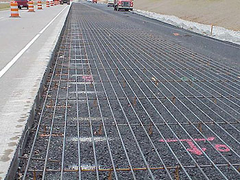
CRCP is a type of Portland cement concrete pavement reinforced with steel rebars throughout its length. The first CRCP was constructed in 1921 on Columbia Pike near Washington, D.C., for experimental purposes, and by the 1940s and 1950s many states began conducting extensive studies on the effects of various designs and construction factors on its performance.(10) The extensive use of CRCP began in the early 1960s during the heyday of the Interstate System construction program, and there are now over 45,080 lane kilometers (km) (28,000 lane miles (mi)) of CRCP constructed in the United States throughout more than 35 states.(11) The use of continuous reinforcement generates the random cracks in the pavement, while obviating the need for transverse contraction joints that appear prone to joint-related distresses and failures. The cracks can be held tightly by the reinforcement and should be of no concern so long as they are uniformly spaced, maintaining the structural integrity of the pavement. Figure 1 shows the longitudinal steel rebars made continuous and the transverse steel rebars supporting the longitudinal rebars.(12)
Figure 1. Photo. Typical example of reinforcement layout for CRCP (constructed on S.R. 288 in Virginia).(12)
The high durability and strength characteristics of CRCP, obtained through its unique design, assure its longevity and low-maintenance cost, and will provide an excellent support for future overlays. Also, the elimination of transverse contraction joints can offer high riding quality. In order to realize such a level of benefit, the CRCP needs to be designed and constructed properly. Otherwise, premature failure will occur when it is subjected to ever-increasing heavy traffic loading.(13) The design and construction features that considerably affect the performance of CRCP are reinforcement ratio, pavement thickness, concrete material properties decided by coarse aggregate type, water-to-cement ratio, chemo-thermo-mechanical behavior, subbase quality and drainage, and reinforcement placement. (See references 1, 14, 15, and 16.) A study indicated that many examples of CRCP over 50 years old were still in serviceable condition and were able to carry traffic loads in excess of their projected design loadings, possessing low-maintenance cost and good riding quality.(16)
The distress most prevalent in CRCP is punchout failure at the pavement edge. There are four types and causes of distresses that commonly occur in CRCP:
Loss of subbase support is the fundamental cause of all the distresses. Instances where nonuniform support has precipitated localized short crack spacing, leading ultimately to punchout failure, have been reported in one study.(14) An optimum crack spacing between 0.914 and 1.219 m (3 to 4 ft) was indicated because the maximum longitudinal and transverse bending stresses are minimized in terms of load transfer.(14) Maintaining high load transfer is critical to CRCP performance, particularly outside of this cracking interval, and is highly dependent on the crack width.(17) The other possible distresses are corrosion of steel reinforcement, blowup at transverse construction joint, and D-cracking adjacent and roughly parallel to cracks as well as along the slab edge.(1,10,18) The corrosion of steel reinforcement also leads to delamination, spalling, and steel rupture.
The design for CRCP is based on empirical equations obtained from the AASHTO Road Test, and further modifications are based on theory and experience.(10) In the AASHTO design method, the procedure for determining the thickness of CRCP is the same as that used for conventional jointed pavement. The only difference in thickness design between the methods is that a slightly smaller load transfer coefficient (which implies more load transfer across the cracks) is used for CRCP, causing the thickness of the CRCP slab to be slightly smaller. However, according to a Portland Cement Association (PCA) report, the critical stresses and deflections in CRCP were about the same as those in conventional pavements, sometimes slightly larger and sometimes slightly smaller depending on the crack spacing, so the use of the same thickness has been recommended.(10, 19)
The AASHTO method for designing longitudinal reinforcement utilizes the nomographs developed by empirical equations. The input variables used for the design are concrete tensile strength, concrete shrinkage, CTE of concrete and steel rebar, rebar diameter, design temperature drop, and wheel load tensile stress. In addition, there are three limiting criteria which must be considered for the design: crack spacing, crack width, and reinforcement stress. The acceptable limits of these criteria (summarized below) can ensure satisfactory performance of CRCP under the anticipated environmental and vehicular loading conditions:(2)
The steel reinforcement ratio adopted varies from region to region. By far, the most commonly used amount of steel reinforcement is 0.6 percent. Under more severe weather conditions, 0.7 percent of steel amount is preferable.(1,3,20)
In 1974, researchers at the University of Texas developed their first computer program for the mechanistic analysis of CRCP. Extensive field studies conducted to verify the validity of the program (CRCP1) indicated that the predictions from CRCP1 agreed with field observations. The effect of wheel load stresses was added to the CRCP behavior due to environmental loading, and the CRCP program was continuously improved by simulating material variance to concrete tensile strength and adding fatigue failure models.(3) Normalized concrete curing curves were determined for various coarse aggregates commonly used in Texas, and these curves and the calibrated failure prediction model were included.(5,21) Finally, all previous versions of the CRCP programs were integrated into one program (CRCP8) for simplification of the user input process.(22) However, CRCP8 still had some limitations spawning from the simplified assumption of the one-dimensional analysis. In 1998, a new program, CRCP9 (which uses two-dimensional finite element theories to create a mechanistic model) was developed.(4) The CRCP9 includes consideration of nonlinear variation in temperature and drying shrinkage through the depth of a concrete slab, the nonlinear bond-slip relationship between concrete and steel rebars, viscoelastic effects of concrete, curling and warping effects, and the ability to change locations of the longitudinal reinforcement. To improve the accuracy of the wheel load stress calculation, the program was updated once again by including the effect of the moving dynamic tandem axle loads (CRCP10).(23)
Steel reinforcement has been widely used for conventional concrete structure. In general, steel reinforcement is chemically protected by the high alkalinity (pH 12.5 to 13.5) of the concrete and physically protected by surrounding concrete cover against corrosion.(24) However, for many structures exposed to aggressive environments (such as marine structures, bridges, loads, and parking garages), combinations of moisture, temperature, and chlorides reduce the alkalinity of the concrete and result in the corrosion of steel reinforcement. The corrosion process of steel reinforcement leads to concrete deterioration followed by the eventual loss of structural serviceability. To overcome corrosion problems, researchers have examined numerous options that can prevent corrosive agents from reaching the steel reinforcement surface, such as applications of epoxy coating and cathodic protection to the steel reinforcement, the use of sealers and membranes, lower permeability concrete, and corrosion-inhibiting chemical admixtures.(25) However, the potential of corrosion problems still remains with the constant presence of corrosive agents, and therefore the effectiveness of these options may vary considerably in the long run.
In recent efforts to solve the corrosion problems in concrete, nonmetallic materials such as fiber reinforced polymer (FRP) composites have become an alternative to reinforcing steel in various concrete structures. FRP reinforcement is primarily made of fibers embedded in a polymeric resin. The small diameter inorganic and organic fibers (e.g., glass, carbon, aramid, and polyvinyl alcohol) provide FRP reinforcement with strength and stiffness, whereas thermosetting polymer resins (e.g., polyester, vinylester, and epoxy) bind the fibers together. In addition, inorganic fillers (e.g., calcium carbonate, clay, and alumina trihydrate) can be mixed with the resins for cost reduction, property modification, and processing property control of FRP reinforcement.
The FRP reinforcement has some advantages and disadvantages in its material characteristics when used in concrete structures:(26)
Therefore, the material characteristics of FRP need to be carefully considered when determining whether FRP reinforcement is suitable or necessary for a particular concrete structure. There are several commercially available FRP reinforcements made of continuous aramid (AFRP), carbon (CFRP) or glass (GFRP) fibers embedded in various resin materials. Also, FRP reinforcements can be sorted by the type of surface deformation system, such as exterior wound fibers, sand coating, or separately formed deformation.
Currently, the structural performance and integrity of concrete structures reinforced with FRP rebars are being studied extensively by researchers in Japan, Europe, and North America in order to investigate FRP rebar structure capability and durability as reinforcement for concrete and to provide FRP design provisions for different applications. A preliminary design method of FRP reinforcement for jointed slabs on the ground is presented in an ACI committee report.(26) The subgrade drag method is frequently used to determine the amount of shrinkage and temperature steel reinforcement as:
| As = | μLw |
| 2fs |
where As = cross-sectional area of steel (in2) per linear foot; fs = allowable stress in steel reinforcement (lbf/in2), commonly taken as two-thirds to three-fourths of yielding stress level; m = coefficient of subgrade friction (1.5 is recommended for floors on ground); L = distance between joints (ft); and w = dead weight of the slab (lbf/ft2) per slab thickness. The drag equation is modified by considering the lower modulus of the FRP reinforcement. At the allowable stress, the strain in steel reinforcement is about 0.0012, and converting the same strain into the stress for FRP will give a stress of 0.0012Ef. Figure 2 can then be rewritten as:
| Af,sh = | μLw |
| 2 ( 0.0012 Ef ) |
where Af,sh = the cross-sectional area of FRP reinforcement (in2) per linear foot; and Ef = Young's modulus of FRP reinforcement (lbf/in2). Comparing figures 2 and 3, it can be noted that the ratio of the amount of FRP reinforcement required to be increased is the same as the ratio of steel to the GFRP Young's modulus. However, according to the ACI report, this design approach still needs to be experimentally verified. More importantly, there is a need to consider the effects due to the difference in CTE and Young's modulus between concrete and the types of reinforcement. An analytical study to address these effects will be presented in the next chapter.

