U.S. Department of Transportation
Federal Highway Administration
1200 New Jersey Avenue, SE
Washington, DC 20590
202-366-4000
Federal Highway Administration Research and Technology
Coordinating, Developing, and Delivering Highway Transportation Innovations
 |
| This report is an archived publication and may contain dated technical, contact, and link information |
|
Publication Number: FHWA-RD-97-146 Date: NOVEMBER 1997 |
Previous | Table of Contents | Next
Cracks in HCC may have several causes (see ACl 201.1R and ACI 224.1R): plastic shrinkage, settlement, drying shrinkage, thermal stresses, chemical reactions, weathering (freezing and thawing, wetting and drying, heating and cooling), corrosion of reinforcement, poor construction practices (e.g., retempering), construction overloads, errors in design and detailing, and externally applied loads.
For our purposes, eight types of cracks are discussed:
1. microcracks
2. crazing
3. scaling
4. cracks due to insufficient air-void content
5. cracks due to delamination at the reinforcement
6. cracks due to a chemical reaction
7. cracks due to drying shrinkage
8. cracks due to plastic shrinkage
The term microcracks includes all the very fine cracks, in any direction, at the surface or within the mass of the concrete that are not easily visible with the unaided eye but may be seen with a magnifying glass or microscope. Microcracks are often extremely difficult to observe on the textured surface of a placement. Chapter 8 provides instructions on the observation and recording of microcracks.
Crazing is a fine, very shallow cracking that occurs in the exposed surface of a concrete placement. Usually, it cannot be seen while the observer is in motion in a vehicle. It may be due to overfinishing, shallow freezing, or curing insufficient to prevent excessive drying, especially in concretes containing fly ash. Frequently, crazing has a very fine pattern, like pattern cracking except the individual uncracked central portions are usually no more than 2 in. across. When crazing causes the surface to flake off, usually to a depth of about 1/8 in., it may be called paper scaling. The crazing depth should be recorded. The underside of any loose flakes of concrete should be examined for the casts of ice crystals that would indicate freezing before hardening.
Areas on the surface that appear to be peeling off are scaling. Scaling is usually shallow, less than 0.75 in. in depth, and may be due to imperfectly performed curing procedures so that layers of concrete that differ in water content are formed. The early loss of curing cover (burlap, polyethelene, or both), thus loss of moisture and heat, and freezing of the top layer before hardening are common causes of scaling.
4.2.4 Cracks Due to Insufficient Air-Void Content
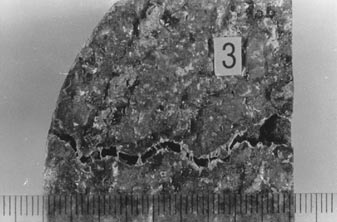
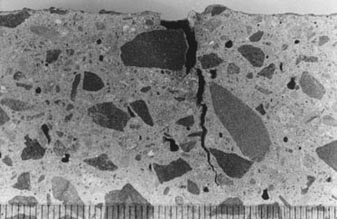
Deeper scaling is usually due to an insufficient air-void content and, thus, lack of resistance to freezing and thawing (see Figs. 3-4 and 8-7).
4.2.5 Cracks Due to Delamination at Reinforcement
Cracks at the level of the reinforcement are almost invariably due to corrosion of the reinforcement and expansion. The high pH of the concrete has a passivating effect that protects the reinforcing steel from the corrosive effects of deicing salts and acid rain. The thicker the layer of concrete over the steel, the better the protection against corrosion of the steel. Any vertical cracking that breaks the surface of the concrete or any wearing away of the surface of the HCC lessens the protection that normal concrete will give the steel. The concrete is considered to have only the depth of protection that exists from the bottom of the cracks to the reinforcement (see Figs. 3-5 and 3-6).
4.2.6 Cracks Due to a Chemical Reaction
A chemical reaction may take place between the aggregate and the paste, especially when moisture is plentiful, or may be brought about by the ingress of destructive chemicals. Such cracking is discussed in Chapter 10.
4.2.7 Cracks Due to Drying Shrinkage
The term drying shrinkage is commonly used in connection with shrinkage cracking that occurs after the HCC has attained final set and a certain degree of bonding has developed between the aggregate and the paste. After the concrete has hardened and is fully set, the paste is a brittle material because it hardened due to hydration of the cement.
Most HCC shows evidence of drying shrinkage. Cracking can be minimized by good workmanship, proper proportioning of the mixture, and sufficient jointing performed soon after hardening. In jointed concrete, cracks may form if the joints were not formed early enough or are not working properly or the shrinkage in the hardened state is excessive. In continuously reinforced HCC, very narrow, fairly regularly spaced cracks are expected to form. The cracks allow for the changes in volume of the concrete with drying and varying temperatures. These cracks are expected to extend down into the concrete and up from the bottom of the slab, but the reinforcement is expected to keep the crack from extending close enough to the steel to allow deleterious solutions to depassivate and corrode the steel reinforcement.
4.2.8 Cracks Due to Plastic Shrinkage
Plastic shrinkage is a form of drying shrinkage that occurs while the HCC is unhardened and malleable and the bond between the components of the material is very weak. Plastic shrinkage cracking is caused by excessive evaporation of the water at the concrete surface due to improper curing procedures for a concrete under the climatic conditions existing at the time of placement (see Appendix D and Kuhlmann, 1991). Plastic shrinkage occurs in the first few hours after placement before final set (when the rate of evaporation exceeds the rate of bleeding). At this stage, the HCC has some properties of a solid, but no appreciable bond exists between the aggregate particles and the cement paste. This sort of cracking is also called early cracking or morning cracking, the latter because it is often the concrete that was placed in the morning and then exposed to afternoon drying conditions that exhibits this type of cracking (see Figs. 4-1 through 4-6).
Plastic shrinkage cracking often occurs in high-quality HCCs in which the distribution of the various components (such as aggregates and cement and any particulate cementitious admixtures) is often nearly homogeneous throughout the mass. The hydration is usually as complete and well distributed as would be expected of any concrete of this age. There appears to be nothing wrong with the HCC itself. It just cracked.
In modern HCCs with a water-cement ratio of less than 0.47, plastic shrinkage cracking seems to have no relationship to the orientation of the reinforcing steel or other structural features. In HCCs with a higher water-cement ratio, there can be a form of early cracking wherein the cracks are located directly over the steel. This cracking is directly related to segregation and settlement of the aggregate over the steel as the bleed water leaves the concrete and the volume of the paste is diminished. As with HCCs with a lower water-cement ratio, this condition was exacerbated by drying atmospheric conditions. Evidence of this type of segregation can be seen on interior surfaces of specimens of these HCCs. The associated cracking used to be called early morning cracking but is now more properly called settlement or subsidence cracking (ACI 224R).
Occasionally, there may be severe bleed channels in HCC that might be confused with plastic shrinkage cracking. However, upon close inspection, such bleed channels show clear evidence of being a waterway, whereas plastic shrinkage cracks show clear evidence of having been pulled open by the shrinkage of the concrete. Such bleed channels are trains of water voids caused by excess bleed water. Such trains of voids may occur in HCCs with a high water-cement ratio. Some forms of plastic shrinkage cracking may have zones of such void trains. In HCCs with a low water-cement ratio, poor consolidation may cause fold lines and collections of voids. Any cracks occurring in such HCCs can usually be recognized by the nature of the voids and the presence of brittle (as opposed to unhardened) fracture surfaces.
The following may occur in unusual and extreme cases of rapid evaporation causing drying of the HCC before hardening:
These are features of extreme drying and are not present in the most common forms of plastic shrinkage cracking. However, the absence of these features does not indicate that the cracking is not due to drying conditions that are deleterious to the HCC.
4.3 DISTINGUISHING BETWEEN PLASTIC SHRINKAGE CRACKING AND DRYING SHRINKAGE CRACKING
For transportation departments and other purchasers of concrete placed by a contractor (or other agency), it is frequently important to distinguish between early plastic shrinkage cracking and the brittle cracking that may occur due to structural stress or later drying shrinkage. The contractor is obligated to prevent the dehydration (and consequent cracking) of the fresh concrete that can occur when wind, low humidity, or both promote rapid drying. Portland cement concretes with a low water-cement ratio (0.40 or less) and latex-modified concretes are more apt to suffer this sort of failure than are concretes with a high water-cement ratio. When it can be shown that the cracking is due to a failure of the contractor to refrain from placing concrete during unfavorable weather conditions, employ sufficient methods to prevent the drying, or both, the contractor may be obligated to provide a new surface or accept a lower payment.
The usual rule of thumb in the literature is: If the cracks go through the aggregate particles and cause them to break, the cracking should not be considered plastic cracking. Many observers call any crack that goes around the aggregate particles a plastic/early shrinkage crack. This can be in error. There may be other reasons for the crack to go around the aggregate particles.
Some aggregates are more fragile than others, and some may crack during final placing and finishing. It is possible to judge a crack to be a later crack on the criterion of broken aggregate when in reality the aggregate particle just happened to have a zone of weakness in the crack plane and the crack was an early crack. The specimen examined, a cross section of a crack, is a very small portion of a crack. The interior of the crack surface is a very small, nonrepresentative portion of the crack.
When the cracks preferentially go around the aggregate particle, the observer may be observing an HCC in which the bond between the aggregate and paste is very poor at any degree of maturity. The bond may be poor because of any of the following:
Thus, it is necessary that the criteria for deciding that a specific crack is a plastic shrinkage crack be more than the fact that the crack skirts the aggregate particles.
4.3.2 Analogy with Clay Materials
The difference between drying shrinkage cracking and plastic shrinkage cracking can be explained further by use of an analogy using clay materials.
If the material is a sandy clay that was fired in a kiln ("fired" is analogous to the hardening of concrete), all the cracked surfaces will fit back together if all the fragments are preserved and there are no air pockets present. If the bond and the tensile strength of the ceramic are as strong as the tensile strength of the sand, then the crack will fracture the sand and the crack surfaces will neatly and completely fit back together. If the sand has much greater tensile strength than the fired ceramic, any cracks occurring in the material are likely to detour around the sand grains.
These facts may be directly extrapolated to hardened HCCs. The logic also applies to cracks in hardened portland cement concrete, hardened latex-modified HCC, and many other highway materials. In the case of these materials, the general type of void and the nature and luster of the interior of the voids should be carefully studied so that they can be recognized in the path of any crack under study.
It may be that a macrocrack occurring on the riding surface of HCC that was originally a thin sharp line was worn wider by the abrasive action of traffic. The course of the crack below the surface expression should be examined. Care must be taken to extrapolate the evidence in the light of all relevant facts, including the age of the placement, the amount of traffic, pertinent weather conditions, and the strength and general condition of the concrete placement.
This is entirely analogous to the situation in plastic shrinkage cracking in HCC. The crack occurs while the material is plastic and is then "baked" (shape preserved) by the continuing hydration of the cement and complete hardening of the HCC.
Distinguishing between drying shrinkage cracking and plastic shrinkage cracking is a five-step procedure, as shown in Table 4-1.
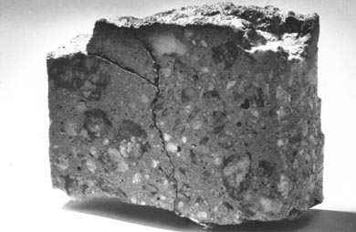
1. Study the intersection of the side walls of the specimen with the wearing surface. Plastic shrinkage cracking may occur before or just after the surface is screeded and the wearing surface texture created. In these cases, it may happen that one or more of the specimens submitted may show that mortar was worked into the top of the crack. Sometimes, portions of the plug of mortar will have fallen out or been chipped off the specimen during coring and handling. It is clear that the plug is a definite indication of early plastic shrinkage cracking (see Fig. 4-1).
Table 4-1
PROCEDURE DISTINGUISHING BETWEEN PLASTIC AND
DRYING SHRINKAGE CRACKING
1. Study the intersection of the side walls of the specimen with the wearing surface.
2. Study the wearing surface of the specimen.
3. Study the expression of the crack on all cut, cored, and lapped surfaces, and focus down into the crack.
4. Examine the interior surface of the crack.
5. If necessary study the type of voids present in other areas of the HCC and compare their surface with various types of surfaces within the crack.
| Figure 4-1 PLASTIC SHRINKAGE CRACKING. Was covered up by mortar filling over it in top of a 4-in, core. Mortar was worked into the top of this set of cracks before the concrete hardened. Later, the concrete cracked in the same area Due to lack of interlock, the new crack follows the mortar boundaries. At the right side of the picture is a depression in the surface where a mortar plug was lost before the photograph was taken (This specimen had to be glued together to enable the photograph to be made.) |
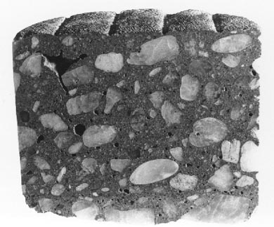
| Figure 4-2 PLASTIC SHRINKAGE CRACKING. Occurred before a surface texture was formed. The defect became hidden by the finishing procedures that pushed unhardened mortar over the crack. |
If the cracking occurred just before texturing, the creation of the wearing surface would naturally work mortar into the crack (see Fig. 4-2). If the cracking occurred after texturing and was observed by the workers, a deliberate effort may have been made to improve a wearing surface that was seen to be flawed.
2. Study the wearing surface of the specimen. With the microscope, look for features that will define the crack. Check for any features that will indicate the nature of the cracks. If photographs can be obtained of the wearing surface just after cracking but before the surface is worn by any traffic, small bridges of material may be seen stretching across the crack, which will indicate plastic shrinkage cracking (see Fig. 4-3).
3. Study the expression of the crack on all cut, cored, and lapped surfaces, and focus down into the crack. If any little bridges of paste are seen that tie the two sides together or if any uncracked aggregate particle bridges the crack, the crack plane existing all around the particle, and the aggregate firmly attached to the hardened paste on either side, it can be concluded that the crack was caused by plastic shrinkage (see Figs. 4-4 and 4-5). Bridges of paste or aggregate are not found in all plastic shrinkage cracks. The defining feature is the fact that the sides of the cracks have been distorted by the tensile forces due to the shrinkage that occurred while the HCC was still malleable.
The greater the difference between the width of the crack at or
near (beneath any mortar plug) the wearing surface and the width of the crack
at its deep end and the more quickly it tapers to nearly nothing, the greater
is the likelihood of the crack having been caused by plastic shrinkage. The
V shape of the crack is part of the distortion of the edges of the crack caused
by the tensile forces. Commonly, the
 |
 |
| Figure 4-3 PLASTIC SHRINKAGE CRACKING. Occurred in a latex-concrete overlay. The crack shows the distortion that accompanies tension cracking in an unhardened medium. This specimen was collected before traffic destroyed these delicate structures. The scales are in millimeters. A. Top view of core. Little threads of latex span the crack. B. Little bridges of latex paste connect sides of crack. |
 |
 |
| Figure 4-4 BRIDGE OF PASTE ACROSS PLASTIC SHRINKAGE CRACK. A. A little bridge of paste across a crack caused by shrinkage that took place while the ordinary portland cement concrete was unhardened (4-in, core; road surface at right). These little bridges may occasionally be found on broken, sawed, cored, or lapped surfaces. B. Close-up of bridge. The scales are in inches. |
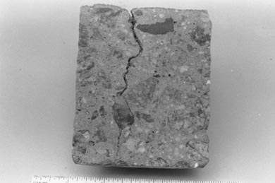
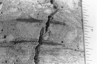
| Figure 4-5 PLASTIC SHRINKAGE CRACK. Tortuous path of a plastic shrinkage crack in a concrete that has not completely separated. It is easy to envision how little bridges of concrete form when a crack system of this nature is stretched further. Narrow microcracks are emphasized with ink. |
crack is a plastic shrinkage crack near the surface, but with depth, the crack is straighter and the zone of weakness has been extended after the final set by other forms of drying shrinkage or by structural stress, sometimes completely through the slab.
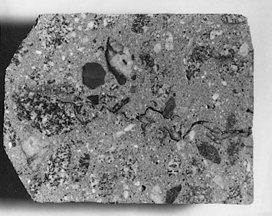
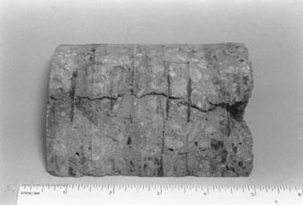
The path of a plastic shrinkage crack on any vertical concrete surface is usually quite tortuous because it is deflected by each piece of aggregate. Typically, the crack is wider at the top than at the bottom, but even at the bottom, it is not the sort of crack found in a brittle ceramic (see Fig. 4-6).
Do not be confused or alarmed by the presence of abundant road dirt or mud created by the drilling of the cores. This mud may appear layered and flaky, but the structures will be fragile.
4. Examine the interior surface of the crack. Delay any destructive procedures until the total surface has been studied and any air-void determinations have been made. Then, break the HCC with a hammer blow in an area away from the crack, and examine the surface produced. In the most common case of a crack produced in an area not including a plastic shrinkage crack, the interior surface will be made up of a multitude of tiny angular planes with the exception of the interior of air voids. There may be an occasional rounded surface of an aggregate particle or of the cast of an aggregate particle, but the major portion of the surface will be a collection of planes.
Break the HCC on the crack, and examine the interior surface.
Usually, the interior surface of a crack produced by plastic shrinkage is made
up of very tiny globules of cement paste. The surface of the paste inside the
crack does not look like a cracked surface. Rather, the paste appears, as one
might imagine it would, as if,
| Figure 4-6 PLASTIC SHRINKAGE CRACK. On a lapped surface. The wearing surface is at the top of the photograph. |
when the sides of the crack were no longer in contact, minute stringers of paste had momentarily bridged the crack and then as the tensile strength of the stringers was exceeded the stringers coalesced into tiny globules. Each globule appears as if a paste stringer shrunk in on itself and made itself equant. If it is a water-worn sand, none of the sand grains will be broken and they will present a natural rounded surface. A few fragments of the coarse aggregate may be broken, as will occur in the fabrication of all concrete. If the aggregate is shaley or naturally fragile and contains a plane of weakness approximately parallel to the plane of the plastic shrinkage crack, the crack may preferentially traverse this aggregate.
5. If necessary, study the type of voids present in other areas
of the HCC and compare their surface with various types of surfaces within the
crack.