U.S. Department of Transportation
Federal Highway Administration
1200 New Jersey Avenue, SE
Washington, DC 20590
202-366-4000
Federal Highway Administration Research and Technology
Coordinating, Developing, and Delivering Highway Transportation Innovations
 |
| This report is an archived publication and may contain dated technical, contact, and link information |
|
Publication Number: FHWA-RD-97-146 Date: NOVEMBER 1997 |
Previous | Table of Contents | Next
Various methods of specimen preparation are used, depending on the nature of the specimen and the information to be obtained. Smoothly lapped specimens are required for quantitative examination with the stereomicroscope. Small loose particles and many fracture surfaces do not require extensive preparation. Examination with the transmitted light microscopes (i.e., the petrographic and P.EF microscopes) requires very thin specimens mounted on glass or very small grains of the specimen mounted in an index of refraction oil or epoxy. The fluorescence features of the P/EF microscope necessitate that the specimen be not only very thin but also impregnated with an epoxy containing a fluorescent dye. Large specimens of aggregate rock can have their properties displayed best through sawing, lapping, and etching. It is often necessary to crush such material for use in specific tests. Bulk specimens of sand, gravel, and crushed aggregate usually require reduction in overall volume and separation into size-graded fractions.
There are three types of slices prepared for stereomicroscopic examination: (1) basic lapped slices, (2) vertical sections of horizontal slices (or vice versa), and (3) acid-etched slices.
The determination of the components, ingredient boundaries, reaction products, and parameters of the air-void system requires the use of a stereomicroscope (see Fig. 2-16). The types of items perceivable with the stereomicroscope are described in Chapter 8. Because it is impossible to focus clearly on a rough surface at the magnifications required for the petrographic examination of HCC with a stereomicroscope, it is necessary that smooth (finely lapped) surfaces be prepared on sawed slices of the specimens. The smoother the saw cut, the easier the lapping routine will be.
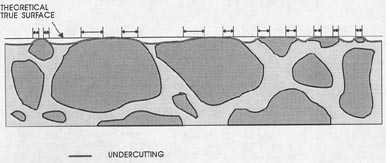
Unless specific precautions are taken to avoid it, undercutting is common during the production of finely lapped surfaces. It is the process in which softer constituents are removed more rapidly than harder constituents so that the harder material (usually the aggregate) stands up higher than the softer components (see Fig. 5-1). During the lapping process, the slice rides on the high, hard portions and grinding compound collects under the soft portions. Hard aggregate standing above an undercut paste has a rounded edge, and the area of visible aggregate is increased. There is no sharp line or change in surface texture at the point where the theoretical flat-lapped surface changes to a slope down into the paste. No exercise of logic or mental reconstruction of what the surface should be will allow an accurate determination of the paste-aggregate boundary or the paste-aggregate ratio in such a slice.
Undercutting is very common on surfaces that are finished on soft polishing laps. It can also occur on hard, cast iron laps but may be greatly minimized with the use of sufficient weight on the back of the specimen to hold the specimen closer to the lap and create additional wear on the high areas. If the specimen is riding on pieces of high, hard aggregate, the buildup of grinding compound in the low, soft portions of the specimen can cause a general rounding of the surface contours, loss of the ability to distinguish boundaries accurately, enlargement of voids, loss of reaction products, and loss of sharpness and clarity on the edges of cracks and other features.
5.2.1.2 Procedures
Producing a lapped slice is a five-step process, as shown in Table 5-1.
Further details on the preparation of surfaces for microscopical analysis may be found in many references, e.g., ASTM C 856 (petrographic examination) and ASTM C 457 (determination of air-void system).
Table 5-1 PROCEDURE-PRODUCTION OF BASIC LAPPED SLICE
1. Cut and shape the slice.
2. Strengthen fragile HCC.
3. Lap the slice.
4. Clean the slice.
5. Check the quality of the lapped surface.
1. Cut and shape the slice. If the specimen is a fill-depth core or an irregular fragment of HCC, it may be so large that it cannot be held in the vise of the large oil-cooled saw (see Fig. 2-4B). In this case, bring the specimen down to a more reasonable shape and size by using the large water-cooled saw (see Fig. 2-3).
Cut a slice of the HCC from the specimen according to the plan for petrographic analysis as devised in Chapter 3. The oil-cooled saw produces smoother surfaces that require less lap time than do surfaces produced with a water-cooled saw. As mentioned in Chapter 3, label all fragments of the original specimen to identify their origin and, whenever possible, their orientation. A slice thickness of 7/8 in. is recommended, but inspect the material after the first cut to make sure that a thicker slice is not required because of the presence of a previously unseen crack or other weakness. If the specimen crumbles or cracks into several fragments after the first saw cut, you may have to cement the specimen back together with a strong epoxy before you can shape a slice.
The slice must usually be trimmed to fit the slice holder of the lapping device. Most holders are circular to allow free rotation. Be careful not to trim away any portion of the area of greatest interest to the client. Often, the portion of greatest interest will be the top, or wearing, surface. In such cases, any trimming will have to be done on the bottom. If there are no obvious differences to be seen between the top and the bottom of the core and the section does not exceed the diameter of the specimen-holding ring of the lap (6 in. for VTRC equipment) in any dimension, a lapped section can be produced that will be representative of the full depth of the specimen. Very often, the lowest inch or so does not require examination unless it is very different from the upper portions.
2. Strengthen fragile HCC. If the concrete is immature, further carbonation of the paste may help produce a satisfactory surface. Carbonation may often be achieved by exposure of the cut surface to laboratory air of moderate humidity (20 to 80 RH) for 48 hr. For most intensive carbonation, the cut specimen can be supported for 10 hr over water that is kept agitated by dry ice. If the container is loosely covered, the carbonation will continue until all the carbon dioxide is dispersed, even after the dry ice has completely sublimed away.
Very fragile specimens may require impregnation. A number of materials and techniques of impregnation are available. Carnauba wax is recommended in ASTM C 457, but it must be used with safety precautions to prevent explosion during the heating to remove excess wax. Roberts and Scali (1984) recommended the use of a 1:5 solution of colorless nylon fingernail hardener in acetone. They are presently using a somewhat safer preparation of the nylon nail hardener in methanol (personal communication). They prefer the commercial nail hardener to a solution of pure nylon because some of the softening ingredients in the commercial preparation are valuable in preventing chipping. The nylon solution may be applied to the HCC at any stage of the lapping as seems necessary. The hardener is brushed on the surface until it fills the cracks and thoroughly coats the interior of the voids. The hardener is allowed to dry before lapping is continued. Very fragile HCC may require the use of the hardener during all stages of the lapping; other HCCs will require the hardener during only the last portion of the lapping procedures. Before examination and determination of the air-void parameters, the hardener should be removed by soaking in the appropriate solvent until the plastic shine is dissolved away. Choice of an impregnating agent should include consideration of the desirability and difficulty of removing the impregnating agent from the surface to be examined.
If epoxy or another permanent substance is used for impregnation, it will become a lasting part of the specimen, prevent the detection of subtle textural differences in the HCC, and obscure the viewing of reaction products and internal surfaces. This may or may not be important, depending on the purposes of the investigation for which the specimen is being prepared. Various techniques may be used to impregnate HCC slices with numerous types of substances. The slice may be soaked in a series of increasing concentrations of various types of impregnating agents or vacuum impregnated.
3. Lap the slice. If the surface of the specimen is quite smooth as it comes from the saw, the coarsest abrasive need not be used. If the grooves from the saw are very distinct, any fine aggregate has loosened, or other gross irregularities are present, begin lapping the surface with the coarsest abrasive. Usually, this is done by hand holding the specimen and hand feeding the grit on a small lap (Fig. 2-6).
Once you are satisfied that the surface has been made as flat as possible with the coarsest abrasive and all saw marks are gone, continue the work on the two mechanical laps with the automatic abrasive feed (Fig. 2-7). Place the specimen slice in the slotted specimen holder on the lap. Adjust the yokes so that the grinding slurry does not drop inside the slotted specimen holders and the specimens rotate freely as the lap moves beneath them. Place the cover plate on the back of the specimen, and place any weights on top of the cover plate. Load the abrasive cup with about 2 heaping teaspoons of the appropriate abrasive, and fill it about three-fourths full of lapping oil. Set the clock for 20 mm of lapping. Inspect the specimens, and make a judgment concerning the next abrasive. Each abrasive should be finer than the last one used and should be used repeatedly until the marks from the coarser abrasive are gone. A good system is to use one lap for all but the finest abrasive and change to the other lap for the finest one. Lap the surface with successively finer abrasives (see list in Chapter 2) until it is suitable for microscopical observation.
4. Clean the slice. From time to time during lapping, when changing to a finer abrasive, when changing laps, and when lapping is complete, clean all surfaces of the specimen gently and thoroughly to remove the grinding compound and debris. Air voids, cracks, and surfaces of reaction products should be free of such materials.
| CAUTION: If the cleaning of lapped slices is not done promptly, the volatile oils will evaporate and the grinding compound deposits will cake and become hard to remove. Therefore, do not allow a specimen that requires cleaning to lose volatile oils or solvents by evaporation. |
If cleaning of lapped slices must be delayed, submerge the slice in a solvent, such as 1,1,1, trichloroethane. Caked grinding compound can make viewing of interior surfaces and the crystal forms of the paste and reaction products impossible and contribute to undercutting and destruction of the specimen. At VTRC, a few minutes of ultrasonic cleaning in solvent are routinely used for cleaning all lapped specimens.
| CAUTION: Use of ultrasonic cleaning equipment may be harmful to the surface of concrete specimens; therefore, such treatment should not be used without care and experimentation (see ASTM C 457). |
WARNING: Do not immerse any portion of your hand in an ultrasonic bath while the ultrasound is on. The cavitation caused by the ultrasound can erode finger nails and damage skin. |
At VTRC, we have not experienced any loss of reaction products or loosening of the aggregates or other surface degradation because of brief ultrasonic cleaning. As an alternative to ultrasonic cleaning, the specimen can be carefully cleaned of grinding compound and loose particles with a soft brush (soft as a baby's hair brush) while it is immersed in a safety approved container of 1,1,1, trichloroethane. It has been reported that a fine, high-velocity spray of solvent (used in an efficient hood) will clean lapped slices efficiently. This procedure has not been tried at VTRC, and we have no evidence concerning the proper pressure and velocity of the spray that would be required to clean without damaging. Whatever cleaning method is used, as much grinding compound and debris as possible should be removed without damaging the surface or any reaction products in the voids.
WARNING: Persons unfamiliar with the hazards of these cleaning compounds are referred to the Chemical Safety Data Sheets published by Manufacturing Chemists Association, Inc., 1825 Connecticut Avenue, NW Washington, DC 20009, or the Materials Safety Data Sheet that may be obtained from the supplier of the compound. |
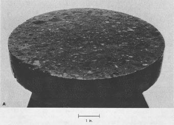
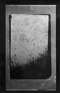
5. Check the quality of the lapped surface. A surface that is satisfactory for microscopical examination (either a general petrographic examination with the stereomicroscope or an analysis of the air-void system) will show an excellent reflection of a distant light source when viewed at a low incident angle. There should be no noticeable relief between the paste and the aggregate surfaces (see ASTM C 457). Such a surface is shown in Figure 5-2.
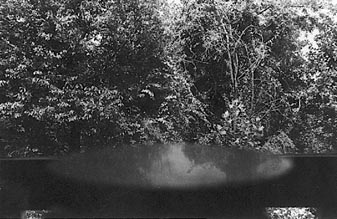
If the day is reasonably bright, scan the light from a window as it is reflected at a very low angle from a finely lapped slice. It should be possible to discern objects such as buildings and trees (see Fig. 5-3).
Alternatively, hold the slice so that it reflects light from an overhead light fixture. It should be possible to see the small details of the diffusion cover of the light or even discern the presence of writing on the light bulb. The edges of the SECTIONS of the air voids will be sharp and not eroded or crumbled, air-void sections as small as 10 µm in diameter will be clearly distinguishable at magnifications of less than 150X, and all cracks will be easily visible and free of debris. The lapped surface needs to show all reaction products, the inner surface of voids, the hydration, etc. in an as-received condition. At VTRC, space and technician time are premium commodities, and the slice used for the air-void determination must be the same surface used for all microscopic evaluations of the concrete sampled and is usually the only slice kept in the archives. If difficulty is encountered in preparing a lapped surface of the proper quality, a common cause is a weak cement paste matrix. The problem is manifested by the plucking of sand grains from the surface during the lapping, with consequent scratching of the surface (as the loose aggregate moves under the surface being prepared) and undercutting of the paste around the harder aggregate particles. A second cause of difficulty may be friable particles of aggregate. For any quantitative analyses, areas that are scratched or imperfect indicate the need for additional
 |
 |
preparation of the specimen. Often, additional cleaning and more time on the free abrasive laps are all that is required.
5.2.2 Vertical section of Horizontal Slice (or Vice Versa)
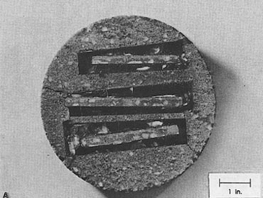
If a horizontal slice was taken from a core in order to study changes in the air-void system (or other feature) with depth, it may later be desired to lap finely and examine a vertical slice of one or more of the lapped slices already available (or vice versa). In such a case, the slice in question must be secured in an upright position in a mounting medium so that a slice that is at right angles to the direction of the first slice can be cut and lapped (see Fig. 5-4).
Etching is performed in order to enhance the differences in acid resistance or solubility that might exist between the phases of a rock or HCC. Some of the phase differences the petrographer might wish to enhance are rhombic dolomite crystals in micritic-carbonate rock, fly ash particles and carbonated areas in HCC, and aggregate particles in HCC paste. Lapped slices of concrete and lapped surfaces on carbonate rock specimens are often etched to make visible and emphasize various phase differences and phase boundaries in the specimen. These differences may be the contrasts between aggregate and paste, various mineralogical differences, and even the differences caused by the depositional and metamorphic history of the rock.
 |
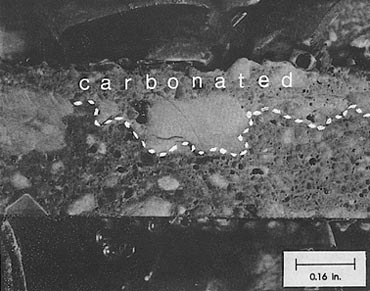 |
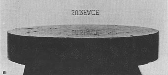
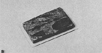
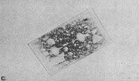
Figure 5-4 SLICE CUT AT RIGHT ANGLES TO ORIGINAL SLICE.A.
Edges of thin top surfaces of a concrete core embedded in epoxy and repotted in mortar in a mold 6 in. in diameter and then resliced and finely lapped to allow examination of the vertical surface. In this case, the concrete was slightly etched with weak HCC to delineate the depth of carbonation. B. Left portion of middle slice shown in A enlarged. The carbonated area is the area above the lower edge of the whiter area near the wearing surface.
The etching of finely lapped specimens of HCC must be delayed until after the specimen has been thoroughly examined and any analysis of the percentage and shape of any constituents that might be changed by the etching is complete (e.g., air). If the etching is being performed to aid in the determination of the paste content for use in the formulas for air-void parameters, the etching and paste determination must be performed on the same surface as was the air-content determination.
Etching a Portion of a Slice. Etching a portion of a slice is a two-step procedure, as shown in Table 5-2.
1. Ensure that the slice is free of oil. The oil used as a lubricant for the lapping must have been removed from the slice by long exposure or oven treatment. Steam must not form in the HCC; therefore, the temperature in the oven must not exceed 90°C.
2. If the etching of only a small portion of the slice is required and the microscope has a working distance sufficient to prevent splattering of the lenses (or the lenses are otherwise protected), drop 10% HCl acid onto the slice from a rod or dropper while the slice is under the microscope. Observation of the active effervescence of CO2 from CaC03 can help locate various mineral species. Take care to distinguish aggregate composed of carbonate minerals from the CaCO3 of the paste caused by exposure to the carbon dioxide of the atmosphere under conditions of moderate humidity.
Etching an Entire Slice. Etching an entire slice is a six-step procedure, as shown in Table 5-2.
1. Ensure that the slice is free of oil. The oil used as a lubricant for the lapping must have been removed from the slice by long exposure or oven treatment. Steam must not form in the HCC; therefore, the temperature in the oven must not exceed 90°C.
2. Flood a shallow, acid-resistant container (e.g., a shallow glass baking dish) with room-temperature 10% HCl acid. Because the acid should be replaced frequently, a shallow bath is recommended.
3. Support the slice (at room temperature) in the acid bath with very small glass, quartz (sand or pebbles), or plastic supports so that the surface does not touch the bottom of the container and the lapped surface is submerged. (If the slice
Table 5-2 PROCEDUREETCHING OF SLICE
Etching Portion of Slice
1. Ensure that the slice is free of oil.
2. Drop 10% HCl acid onto the slice while the slice is under the microscope.
Etching Entire Slice
1. Ensure that the slice is free of oil.
2. Flood a shallow container with room-temperature 10% HCl acid.
3. Support the slice in the acid bath.
4. Move the slice around for a few seconds.
5. Rinse, dry, and microscopically determine if the procedure should be repeated.
6. After the etching is complete, rinse the surface with tap water and partially
dry it.
is not too large or heavy, it may be hand held. The weak acid will not damage healthy skin.)
4. Move the slice around or vibrate it or agitate the acid while the slice is in contact with the acid for a few seconds.
5. Rinse the slice, partially dry it, and microscopically determine if the procedure should be repeated. If the etching is insufficient, return the slice to the acid bath and repeat the procedure. It is generally satisfactory to perform the etching for 5 to 20 sec. The exact time used depends on the maturity and condition of the HCC and the features to be examined.
6. After the etching is complete, rinse the surface with tap water and partially dry it. Drain the slice onto a paper towel, and pat it lightly with a tissue. The slice will usually air dry sufficiently for microscopic examination in 1 hr but may be dried in a slightly warm oven.
Thin sections must be thin enough for sufficient light to pass through them to en able the microscopist by using the particular features of the microscopes (see Chapters 12 and 13) to identify the various parts of the specimen that make up the whole, their nature and present condition, and any changes that have occurred since their original formation. Thus, the sections should be as thin as is practical. Instructions for fabricating standard thin sections from rock for examination with the petrographic microscope are available in many good books on optical mineralogy or petrology and are usually included with any equipment purchased for this purpose. Special instructions for preparing thin sections of HCC, thin sections for study with fluorescent light, and thin sections of particular aggregates are included here.
The thickness of thin sections fabricated for the usual geologic/petrologic/mineralogic examination of rocks and minerals is 25 to 30 µm. If rock or rocklike specimens are sent to a company that fabricates thin sections without further instructions, the thin sections produced will be 25 to 30 µm. For the determination of the component minerals in coarse-grained igneous and metamorphic rocks, this thickness generally works fairly well. Some rock-oriented petrographers depend on thin sections being a standard thickness so that they can more easily judge the birefringence of a mineral grain under observation by the dispersion caused by the standard thickness. On the other hand, many concrete petrographers prefer to work with much thinner thin sections. They have become accustomed to judging birefingence by comparison between mineral species. When the size of the individual particles of interest is less than the thickness of the thin section, the particle boundaries tend to become obscured by the overlap of the particles. The finer the size of the particles, the more difficult it is to observe and define the boundaries. The less the difference between the various optical properties of the particles (index of refraction, color, and birefringence), the more difficult it becomes to identify the boundaries and determine the identity of the particles. Some of the aggregates whose structure must be determined accurately in concrete petrography are very fine grained. The microstructure of the deleteriously reactive carbonate aggregates cannot usually be deciphered in thin sections of standard thickness. These rocks are composed of rhombic crystals of dolomite (5 to 20 p.m across) "floating" in a murky, calcite micrite. The murky appearance of the background is caused by submicroscopic particles of organic material, iron oxides, sulfides, and various other insoluble substances that are included in the micrite. When these materials include a relatively high percentage of opaque material, it can be impossible to discern details in a thin section as thick as 20 µm. The micrite itself may have a grain size of less than 5 µm.
The undulating extinction of alkali-reactive coarse-grained quartz can usually be seen in sections 25 to 30 µm in thickness, but much of the reactive quartz present in metabasalts, mylonites, and siltstones is exceedingly fine grained and cannot be detected in thin sections of standard thickness.
Most cement is very fine. The greater portion will pass a No. 200 (75 µm) meshsieve. The cement hydrates into even finer particles of low to negligible birefringence with nearly identical color and low indices of refraction. Observation of a thin section of HCC 25 µm in thickness could lead a rock-oriented petrographer to state that the material between the aggregate grains is groundmass. The term groundmass has long been used by geologic petrographers to indicate that the material is too fine for determinative microscopy. Examples of groundmass are the submicroscopic clay background of some sedimentary rocks and the material between phenocrysts in lavas or very fine-grained basalts.
Ideally, thin sections should be flat and cover a large portion of the glass on which they are mounted. Unless special equipment (not available at VTRC) is used, the flaws of lack of flatness and small areal extent will sometimes have to be overlooked and data will have to be obtained from small thin sections that are thicker in the middle than at the edges.
Because these specimens are so thin, they must be mounted on glass microscope slides. Because of the thinness, the chance of lapping too far and losing the entire thin section is great. Table 5-3 lists the necessary steps.
1. Prepare the specimen. Begin fabrication with a number of shaped pieces of specimen so that the likelihood of two or more pieces surviving the procedure is good. Shape these blanks slightly smaller than the size of a petrographic glass slide with a small thin-bladed rotary diamond saw (Fig. 2-5). If ultrathin fluorescent sections are being produced, size the shaped pieces to fit the well of the slide.
2. Prepare the glass slide. Ensure that the two sides of the flat glass slides are parallel and that the slides are all of the same thickness. This is accomplished by
Table 5-3 PROCEDURE-PREPARATION OF BASIC THIN SECTION
mounting the slides in the vacuum chuck of the grinder (see Fig. 2-11) and grinding them to a standard thickness as measured on the dial on the right side of the machine. If this is done, it then becomes possible to use the reading on the dial as an indicator of the thickness of the specimen and thus to grind all thin sections to a standard thickness before the hand lapping is begun. The matte surface produced by the grinding of the slide to parallelism and standard thickness may provide a less slippery surface to which the mounting epoxy can cling. If it appears that the cutting and grinding equipment has lost its accurate parallelism between the face of the chuck and the saw or cupped grinder, place a mark on the glass slide indicating the orientation of the glass on the vacuum chuck so that, after the specimen is mounted, the glass may be replaced on the chucks in the same position and thus compensate for any errors in the equipment itself. The 25-year-old equipment at VTRC is still free of this sort of deterioration.
3. Make the first thickness reduction. Mount the piece of specimen for the thin section on the prepared glass slide. Place the glass slide on the vacuum chuck of the cutoff saw (see Fig. 2-11A), and use the handle to move the work into position up against the saw to remove all but 1 p.m. or less of the specimen. The optimum thickness will depend on the physical stability of the specimen. The relative position of the chuck to the saw or grinder can be adjusted with a small dial at the right-hand end of each piece of equipment.
4. Make the second thickness reduction. Transfer the specimen chip on glass to the vacuum chuck on the grinder. Gradually advance the thin-section blank to the grinder by using the thickness measuring dial at the right-hand end. An attempt to grind off a great thickness all at once will induce stresses and may cause breakage or debonding of the specimen and the glass.
5. Perform the final finishing. After the grinder has reduced the section to about 30 µm in thickness, hand finish the section with No. 600 SiC and 5 µm Al203 in a water or oil slurry on a glass plate (see Fig. 2-12) until the section is approximately 25 µm or less in thickness, depending on the material being sectioned and the purposes of the examination. The grinding motion used should be that of making the numeral 8 and should cover as much of the entire surface of the glass as is possible without letting the edge of the glass touch the section being produced. The 8s should move over the glass surface and rotate, crossing as many different places on the glass as possible.
| CAUTION: Examine the glass plate regularly for flatness. When it becomes dished due to the grinding action, discard and replace it. |
For most purposes, the pressure on the back of the thin section should be evenly distributed and just sufficient to slide the section around on the abrasive when sufficient fluid lubricant is used.
5.3.2 Thin section for Detecting Alkali-Reactive Textures in Carbonate Rock
5.3.2.1 Overview
Because the most reactive textures in carbonate rock contain dolomite crystals that are very small (less than 25 µm across), it is necessary to make the thin section used to discern the reactive texture thinner than the usual 25 to 30 µm that the tiny rhombs of dolomite (often only half the thickness of a standard mineralogical thin section) can be seen without being obscured by other overlapping phases.
The thin section may be lapped down to zero thickness at one end and wedge toward a more standard thickness at the other (see Fig. 5-5). This may be accomplished by pressing more heavily on one end of the back of the section during the final finishing. By this method, there will exist at least a small area that is of the correct thickness to allow visibility of very small dolomite crystals. The pressure on the back of the section should be kept nearly evenly distributed until the section is down to about 25 µm in thickness.
The best thickness for viewing the texture of carbonate materials is usually achieved when observation with crossed polarizers indicates that much of the carbonate shows a pink of the fourth order (or less) and the overall glaring high order white, generally typical of the carbonates, has begun to change to colors. Experienced technicians may thin the entire section to the thickness best suited for viewing, but the likelihood of loosing the entire section is very great.
I estimate that the best compromise thickness for sections of concrete and some aggregates is about 10 µm Each material studied will probably have its own optium thickness. Unfortunately, the optimum is often quite thin and difficult to achieve without loss of the entire specimen cemented to the glass.
5.3.3 Thin section Showing Profile of Wearing Surface
On occasion, the exact details of the texture and the aggregates of the wearing surface of an HCC pavement require examination and study with the petrographic microscope (Webb, 1970).
Cement two small portions of the surface under study to a slide with the wearing surfaces together in the center (to protect the area of interest from the greatest thinning action), and produce a thin section of the thickness appropriate for the material and the purposes of the study. Figure 5-6 illustrates some of the steps in this process.
5.3.4 Thin section for Epifluorescent Illumination
sections for use with epifluorescent illumination (see Chapter 13) are much like ordinary thin sections. The person fabricating the thin sections should become familiar with the material in 5.3.1. (The welled slides used for fluorescent thin sections require no preparation.) The major difference is that the thin sections are impregnated with a fluorescent-dyed epoxy (Walker & Marshall, 1979; Wilk, Dobrolobov, & Romer, 1974). In these sections, the light emitted by the fluorescent dye is not collimated by the condenser because it is produced in the section, closer to the objective lens than is the condenser. Therefore, the thinness of the section is of great importance in preventing the obscuring of fluorescent details with fluorescent light from greater depths. Because the section is of concrete (usually with considerable porosity) that has been impregnated with a dyed epoxy and properly cured, it is not so difficult as might be thought to produce sections of 15 µm or less in thickness.
The methods used by VTRC to fabricate fluorescent thin sections (Walker & Marshall, 1979) were those that would involve the least cost for equipment. The Ingram-Ward thin-section equipment was already available, and the major purchases were the vacuum oven and the Syntron vibratory polishing lap.
It was found necessary to make sure that the most impregnated side of the thin section blank was very flat and was cemented down to the final slide to be used because the impregnation was usually only about 1.5 p.m in depth. With the Ingram Ward equipment, the use of a series of work glasses was necessary. Other laboratories could easily devise other methods of producing these sections, depending on the equipment available to them.
 |
 |
 |
The fabrication of fluorescent thin sections is a 23-step process, as follows. When not in use, store the specimen in a dark, airtight cabinet (to prevent fading of the fluorescence). To prevent carbonation, use an effective desiccant, such as Drierite, and a carbon dioxide absorbent, such as Ascarite.
1. Select and mark the specimen area. Generally, the area selected should be centered on mortar rather than on coarse aggregate. The area should be about 16 by 32 mm to fit the welled area of the final mounting glass.
2. With the small diamond blade saw, and preferably an oil lubricant, cut a small specimen about 4 mm in thickness from the specimen area. Extremely fragile specimens may necessitate thicker specimen chips.
3. Rinse the specimen well in acetone or 1,1,1, trichioroethane, and allow to dry. Carefully, so as to ensure parallelism, mount the specimen on a flat work slide with a mounting epoxy.
| WARNING: Persons unfamiliar with the hazards of these compounds are referred to the Chemical Safety Data Sheets published by Manufacturing Chemists Association, Inc., 1825 Connecticut Avenue, NW Washington, DC 20009, or to the Materials Safety Data Sheet that should be obtained from the supplier of the compound. |
4. Mount the glass slide in the vacuum chuck of the Ingram-Ward grinder, and grind the specimen chip with the cupped ceramic diamond grinder until the entire surface of the specimen is free of saw-damaged material.
5. Wash by soaking in four changes of acetone over a period of 2 hr to remove the lubricant oil. Air dry.
6. Dehydrate the preparation overnight in a vacuum oven at 80ºC. Maintain a vacuum of 10 mm Hg for about 1 hr before leaving for the night. In the morning, turn off the heat and allow the closed oven and slice to come to room temperature before releasing the vacuum.
7. Pot the specimen with the ground surface up (glass down) in a container of liquid fluorescent epoxy to which has been added some 0.3 Linde (see Chapter 2) to protect the edges during later polishing. At VTRC, a disposable plastic Petri dish (5-cm diameter) is used as a potting container. (If the corners of the work glass have to be snapped off to make the preparation fit in the dish, a second work glass will have to be cemented onto the back of the first one before the preparation can be held in a vacuum chuck again.) The use of a larger container would waste epoxy.
8. Place the container in the vacuum oven at room temperature, and bring the vacuum intermittently and slowly down as low as possible (10 mm Hg). Keep it there until outgassing stops. This step is best done in stages to prevent overflow of the bubbling epoxy (see Figure 2-14B) and allow the impregnating epoxy time to penetrate the slice. Release the vacuum, and allow the air pressure to force the epoxy into all portions of the void system. Repeat the procedure as many times as necessary until very few bubbles form while the preparation is under a vacuum. On the last treatment, continue the vacuum until outgassing essentially stops. The entire procedure can take up to 3 hr.
9. Cure the epoxy in a warm oven overnight and then at room temperature for 36 hr or until the epoxy is hard and brittle and does not show any plasticity when tested with a pick. There must not be any possibility that the epoxy in air voids or cracks will become distorted and drag onto adjacent phases. If experimentation concerning the curing is performed, be aware of the fact that subjecting the epoxy to a vacuum may remove some of the more volatile components of the epoxy mixture and may thus change the curing regime required. Treat any experimental curing slices the same as any impregnated material.
It is necessary that the lapping procedures to follow remove the impregnating epoxy by the same infinitesimal chipping method as used for removing the aggregate rock and cement paste.
10. Trim excess hardened epoxy, plastic (from the container), and glass from around the sides of the specimen with the small rotary saw. With a knife, snap off the plastic. Peel the external hardened epoxy from the bottom glass of the impregnated slab. Attach an additional work glass with quick-set glue. (This work glass is required for the next step to ensure that all the ports of the vacuum chuck are fully covered and working efficiently.)
11. Clean the final mounting surface by placing the new work glass on the vacuum chuck of the Ingram-Ward grinder and carefully grinding off the hardened epoxy coating on the surface of the specimen. The sound of the grinding will change when the epoxy layer is gone. Remove as little of the specimen as possible. This highly impregnated area is the best portion to use as the thin section.
12. Lap the mounting surface by hand with a 5 µm Al2O3 water slurry on glass.
| CAUTION: Examine the glass plate regularly for flatness. When it becomes dished due to the grinding action, discard and replace it. > |
13. Clean the specimen in an ultrasonic cleaner with acetone solvent.
| WARNING: Do not immerse any portion of your hand in an ultrasonic bath while the ultrasound is on. The cavitation caused by the ultrasound can erode fingernails and damage skin. |
14. Place the specimen under a 10-mm vacuum at 50°C for 3 hr or more to remove all oil and water. (Do not use heat. It may soften the epoxy.)
Mount the specimen, with the lapped impregnated surface down, in a welled petrographic slide with an undyed epoxy. Perform the mounting carefully to elimi- nate air pockets and ensure a good bond.
16. Firmly, but without destructive force, clamp the specimen to the slide and allow it to cure overnight. Be careful to limit the forces to those that will clamp the specimen to the glass. Do not twist or slide the specimen relative to the welled glass slide. The clamp stand used for this procedure is shown in Figure 2-15.
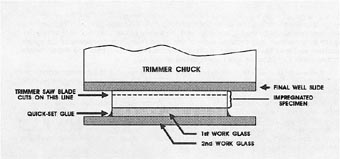
17. Cut off the excess thickness of the specimen by mounting the welled slide containing the specimen against the vacuum chuck of the Ingram-Ward saw, as shown in Figure 5-7. The specimen will be made reasonably thin, and the two work glasses removed.
18. Reduce the specimen to about 30 µm in thickness in the Ingram-Ward grinder.
19. Rinse the specimen well with acetone or 1,1,1, trichloroethane.
20. Lap the specimen by hand with a 5 µm Al2O3 and water slurry on glass. (Refer to instructions in 5.3.1).
21. Clean the specimen in an ultrasonic cleaner with acetone.
22. Attach the glass of the specimen slide to the flat side of the weights of the Syntron vibratory polisher with strong double-sided adhesive tape (carpet tape). Place rubber bumper rings on the weights. Spread the Pellon pad in a bowl on the vibrator with a slurry of diamond compound (the coarser first) and lapping oil. Place the weighted specimen down on the treated Pellon pad (see Fig. 2-16), and activate the vibrator for as long as necessary to reduce the specimen to the required thinness and produce a very finely textured flat surface free of scratches. The vibration may require 8 to 16 hr. Certain types of concrete with especially resistant aggregate will require further polishing to remove scratches. In such a case, thoroughly clean the specimen and weights and repeat the vibratory procedure with 1-µm diamond compound in a second Syntron bowl. The use of a second bowl makes it possible to save the first Pellon pad and associated diamond compound for later use.
23. Clean the specimen carefully with acetone or 1,1,1, trichloroethane.
24. When not in use, store the sections in a dark (to prevent fading of the fluorescence), airtight cabinet. To prevent carbonation, use an effective dessicant such as Drierite and a carbon dioxide absorbant such as Ascarite.
Small particles of rock, paste, reaction products, and sand grains can be identified and examined with the petrographic microscope, but they cannot be examined unmounted. The relief between the index of refraction of the substance and the index of refraction of air is so great that the internal reflection within the particle prohibits observation of any useful properties. Therefore, it is necessary to prepare mounts in which these particles are submerged in a transparent substance with an appropriate refractive index. Such mounts are called grain mounts. Temporary grain mounts are usually made with oil for the purpose of determining the index of refraction and other optical properties of small particles of material. The oil can easily run off the mount, and, in time, will evaporate. Permanent grain mounts are made with epoxy and can be kept indefinitely for demonstration and archival purposes. Permanent grain mounts can be thinned in the Ingram-Ward equipment as are thin sections (see 5.3.1) to increase the transparency of the particles and facilitate the observation of many of the optical properties of the material.
Grain mounts are more satisfactory if the particles in any one mount are nearly the same size. Use the 3-in. sieves to separate the sizes. If the examination is concerned with the relative amounts of the sizes, weigh each sieve fraction.
1. Crush or size the particles so they may be distributed evenly on a microscope slide.
2. Place a drop of index of refraction oil on or very near the particles and mix the fragments and the oil with a needle.
3. Drop a small thin cover slip on the preparation.
4. Manipulate the mixture to remove bubbles by moving the cover slip around by means of a clean pencil eraser on a hand-held pencil. If the particles are so large that the cover slip is not in contact with the oil across the total preparation, either add more oil or discard the grain mount and begin again with smaller particles. If the grain mount is being made to aid in the determination of the index of refraction, it is best to start with a supply of particles less than 25 µm in diameter. A number of grain mounts using different oils will probably be required, and, in the interests of economic use of the expensive oils and neatness, each should be as thin and small as is practical. The orientation of the individual grains may be altered by moving the cover slip and thus rolling the fragments.
5. Label each preparation. It is easy to forget which is which when several are on the table beside the microscope. Temporary labeling may be accomplished by placing the grain mount over a label on a sheet of paper. Such preparations may also be used for cursory examination of reaction products when the information needed is easy to obtain, such as birefringence.
Fabricate a permanent grain mount with epoxy, Canada balsam, or a similar substance rather than an index of refraction oil. Such mounting materials may be used purely to preserve the specimen or provide a secure base so that once the mounting material is properly cured the preparation can be thinned and finely lapped as a thin section of the material.
Rock as large fragments, crushed and sized for use, or as sand and gravel may be submitted to the concrete petrographer in order to determine its suitability for use as aggregate in HCC. Specimens may be submitted as part of ongoing research concerning some form of HCC deterioration or for comparison with the aggregate found in HCC specimens presently undergoing investigation. The aggregate specimens can be best examined and tested if they are properly prepared for the proposed examination and testing (see ASTM D 75).
Particulate materials become segregated into sizes or into mineralogical portions when they are stockpiled or even when they are shoveled or poured into small piles The ability of the particles to move over each other and the substrate is affected by the density, geometry, shape, and surface texture of the particles (Mullen, 1978). Air resistance may affect the placement of very fine sizes of materials. Each type of material has its own elasticity and inherent bounce characteristics. These properties can cause both vertical and horizontal segregation within a pile of particles.
5.5.2.1 Hand Specimen and Large Fragment of Rock
1. For each type of rock represented, prepare freshly broken surfaces and sawed surfaces in at least three directions at approximately 90º to each other.
2. If the rock contains a large percentage of carbonate minerals, fine lap the sawed surfaces and etch (with 10% HCl) the lapped surfaces to ascertain the direction of the bedding and emphasize the different mineral compositions.
3. Examine the broken and etched surfaces. Describe the color, condition, parting, lithology, etc. Pay special attention to any indications of reactive aggregate.
4. Crush the specimens to the size required for testing. Be careful that the portion selected is representative of all the kinds of aggregate submitted as one specimen. Treat the crushed aggregate as if it had been submitted in the crushed state. Refer to instructions in 5.5.2.2.
5.5.2.2 Sand, Gravel, Crushed Stone, and Slag
1. Ensure that the specimen has been treated (washed or not) and sized as will the aggregate that is being considered for use in HCC. Dust and mud coatings may wash away. Sizing may allow exclusion of certain types of particles from consideration by indicating that they are such a small fraction that they can be ignored. When the specimen becomes beneficiated by such procedures, these procedures may be required of the aggregate supplier before the aggregate is accepted for use. Refer to Dolar-Mantuani (1983) and other applicable references in the Reading List for more information.
2. Inspect the entire specimen for the presence of the types of particles whose presence in even a small amount can cause the aggregate to fail the client's specifications. Roughly estimate the percentage of such particles.
3. Select a number of small portions to represent the whole for use in tests and examinations. Each portion to be tested must contain the same proportion of lithologic and mineralogic types and the same proportion of sizes, coatings, and impurities as the original specimen (see ASTM C 702). Take care that the reduction in sample size does not change the percentage of the undesirable types of particles mentioned in Step 2. The best method for reducing the quantity of the specimen to an amount usable by any test proposed should include the use of a number of sizes of sample splitters. For the finer sizes of sand, very small sample splitters may have to be constructed in the laboratory from such materials as Popsicle sticks. If the aggregate is fairly dust free and sample splitters of the proper size are not available, the material may be repeatedly halved by the cone and alternate quarter removal method: Construct a cone-shaped pile of the aggregate (on canvas-covered floor, table, etc.). Quarter the sample using a thin board or trowel. Carefully remove and combine alternate quarters. Sweep clean the area beneath each quarter removed, and place the small fragments and dust with the removed material. Repeat the procedure as many times as is necessary to reduce the total specimen of aggregate to the quantity required for whatever testing is to be performed. Do not reduce the specimen below the amount required by the examination or test to be performed.

