U.S. Department of Transportation
Federal Highway Administration
1200 New Jersey Avenue, SE
Washington, DC 20590
202-366-4000
Federal Highway Administration Research and Technology
Coordinating, Developing, and Delivering Highway Transportation Innovations
 |
| This report is an archived publication and may contain dated technical, contact, and link information |
|
Publication Number: FHWA-RD-97-146 Date: NOVEMBER 1997 |
Previous | Table of Contents | Next
10.1 OVERVIEW
The concrete petrographer is often called upon to explain the causes of deterioration
of an HCC placement. The determination of the severity and extent of the distress
must include an examination of the placement. The laboratory work of the petrographer
includes identification of the aggregates involved in the reaction, examination
of cracks and crack surfaces, identification and study of any reaction products,
and performance of various tests of the nature of the aggregates and their reactions.
Concrete is fabricated by placing aggregate consisting of gravel, sand, or rock fragments or other mineral material in a very active chemical environment. The fluid of fresh cement paste is a saturated solution of calcium hydroxide. This solution is very alkaline; a pH of 13.5 is not uncommon. These alkaline solutions are so strong that they will chemically burn skin, etch glass, cause dissolution of many siliceous rocks, and cause chemical and volume changes in certain carbonate rocks. They are much stronger than any alkalies that are to be found in any of the solutions to which rock might be subjected during the natural weathering and degradation cycles in normal geological environments.
Because of the different chemical reactivities of the ions and their different sizes, the alkalies (in cement) are reported as the weight percentage of the sodium oxide (Na2O) plus 0.658% of the weight percentage of the potassium oxide (K20). At the present time, the alkali content of most cements in Virginia is reported to range from about 0.55% to 0.70%. In eastern Canada (where deleterious expansive alkali-silica reactions are a severe problem), the alkali content is above 1.5% for cement in many of their cement manufacturing plants. The lower the alkali content, the less severe the alkali-aggregate reaction will be. Cement is not always the only source of the alkalies involved in the deleterious reactions. Deleterious alkalies may come from ground water, sea water, deicing chemicals, fertilizers, or other sources.
All ordinary hardened cement paste contains water of crystallization, crystals of calcium hydroxide, and, depending on the rainfall, humidity, and water table level, a certain amount of interstitial water. In all hardened concrete, there is an interstitial saturated solution of calcium and other hydroxides.
The role of aggregates in concrete was originally perceived to be entirely mechanical. Aggregate particles were thought to be unaffected by the concrete paste and were selected on the basis of their physical properties, such as shape, density ("specific gravity"), surface texture, and amount and interconnection of internal surfaces. However, there are chemical reactions that take place between the aggregates and the paste. Within a concrete mass that contains aggregate particles with a variety of lithologies, there are differences in the interfacial zones that are dependent on differences in the chemical and microstructural nature of the aggregate. The differences in the reactions at the aggregate-paste bond are most easily detected and identified by examination of thin sections of the concrete with the petrographic or P/EF microscope. Such an examination will show that the microstructure and chemical constituents of the bond area vary with the lithology of the aggregate particles. It can be shown that, on occasion, this zone of chemical reaction can increase the strength of the concrete. This increase in strength is usually due to the filling of bond-area cracks with cementitious reaction products that have not caused any deleterious expansion.
There are two major types of deleterious alkali-aggregate chemical reactions that can occur in HCC when the aggregate type and chemical constituents of the paste are such that these reactions are possible: the alkali-silica and the alkali-carbonate reactions. Both of these reactions are deleterious when they cause sufficient expansive force within concrete to rupture the concrete despite the restraint of the mass of the placement and the powerful bonding within the cement paste. If the expansive force is so minor that it cannot overcome the restraint imposed by the concrete, then no deterioration occurs (Hilton, 1974; Houston, 1969).
The first known of the alkali-aggregate reactions was the alkali-silica reaction. It was first reported by T. E. Stanton in 1940 as a reaction of the alkalies of the cement with aggregates in California that contained opal (Stanton, 1940). In the earlier literature, it was called the alkali-aggregate reaction (Diamond, 1978). This is a reaction between the hydroxide ions associated with the dissolved salts of sodium and potassium and the silica molecules of certain imperfectly crystallized siliceous rocks and minerals, such as opal, chert, and cristobalite, or highly siliceous volcanic glasses or highly strained or granulated siliceous rocks, such as the metaquartzites, other stressed silicates, and exceptionally fine-grained siliceous rocks (such as siltstones and phyllites). The reaction produces a silica gel that will expand in the sence of moisture. The expanding gel causes cracks in the aggregate and paste. The cracks allow more moisture to enter and expansive gel to fill the cracks and cause more expansion.
It is the hydroxide ions associated with the sodium and potassium ions in solution that cause the deleterious reactions. These alkalies are not always present in sufficient amounts to cause a noticeable reaction. When the percentage of Na2O plus 0.658% of the K20 is less than 0.60% of the cement, the cement is generally deemed to be too low in alkali content to contribute significant expansion due to the alkali-silica reaction. At the present time, we do not know if this is a sufficiently low limit for the alkali content. According to Bryant Mather, it is not sufficiently low for the conditions in certain western states (B. Mather, personal communication, October 1991).
Low-alkali cement was thought to be generally available in Virginia. Changes in cement production methods in order to use fuel more efficiently and comply with environmental regulations have placed controls on the emission of stack gases into the atmosphere. Therefore, the alkali content of cement has increased (occasionally as high as 1.0%). In any case, we now know that some of the cement obtained years ago was not, continuously, as low in alkalies as it was thought to be. At the present time, we are finding that, in some cement plants, the cement produced in the winter is more apt to be high in alkalies than the cement produced in the warmer months, presumably because of the temperature differentials in the stack.
With the exception of the pure limestones and dolomites, almost all rocks contain some silica. Silica is the most common oxide in the earth's solid crust. The more soluble the form of the silica, the faster and more intense is the reaction. Varieties of naturally occurring silica minerals are listed in order of decreasing reactivity in Table 10-1. This list is very general because, of course, the order is dependent on the degree of disorder to be found within the particular variety and mode of occurrence of the species.
Table 10-2 shows other rocks listed in order of decreasing reactivity. This list is also very general because the order in the list is dependent on the degree of disorder to be found in the particular variety and amount of the deleterious component present.
The expansion in these reacting concretes is caused by the most poorly crystallized portion of the silica-bearing reactive material dissolving in the highly alkaline sodium/potassium-alkali pore solution of the paste and forming an expansive gel within the siliceous particle. With expansion, the gel migrates out of the particle and can permeate the paste and collect in entrapped voids, pores, and microcracks or both. The gel formed at the aggregate surface and that formed before hardening (usually distributed interstitially throughout the paste) are high in lime. These
Table l0-1
SILICA MINERALS IN ORDER OF DECREASING REACTIVITY
Table 10-2
ROCKS IN ORDER OF DECREASING REACTIVITY
high-lime gels are thought to be innocuous and unable to expand. Pozzolanic materials cause rapid reactions with the alkalies and cause the alkalies to be contained in the innocuous (nonswelling) gels. Gel masses formed later, especially within the aggregate, are able to absorb water and expand. This gel ruptures the aggregate particles and collects in pockets, cracks, and crevices. The gel in such pockets may expand, open any microcracks, and create new cracks. Sometimes, the entire center of a highly reactive aggregate particle, such as chert, may be converted to an expansive gel that can create, ooze out into, and enlarge microcracks. When the concrete is broken or cut open, many large cracks may be seen radiating from reactive particles. Destructive cracks may also be found radiating from gel-filled pores and voids.
Once the reaction has started in a concrete, it will continue to complete deterioration as long as deleterious alkali ions, reactive aggregate, and water are available. There is no known way to neutralize the reaction without damage to the concrete.
The speed of the reaction depends on the solubility of the silica-bearing minerals involved, type of gel formed, amount of water-soluble alkali sent, and availability of water. Good drainage will slow down the reaction. A good air-void system may slow down the expansion. A low water-cement ratio or the low permeability contributed by GGBFS or certain mineral admixtures, such as most pozzolans, will slow the movement of water through the concrete or vent and thus slow the reaction and the subsequent expansion. Conversely, a high water-cement ratio with high-alkali cement will speed the process (see Appendix F).
The petrographer should go to the placement and inspect the distressed concrete if the client is concerned about the possibility of an expansive alkali-aggregate reaction or the petrographer suspects an alkali-aggregate reaction because the photographs of the placement furnished by the client or the specimens of distressed concrete show evidence of such a reaction (see ACI 201.1R). The evidence may be any of the following:
Table 10-3
FACTORS TO BE CONSIDERED IN FIELD EXAMINATION FOR
ALKALI-AGGREGATE REACTIONS
see a siliceous rock available in sufficient quantities to be used as an aggregate that has such a perfect crystal structure that I would consider it nonreactive)
Five items should be considered, as listed in Table 10-3: (1) the crack pattern;(2) structural evidence of expansion; (3) rocks and minerals in the aggregate of the distressed placement; (4) exudations, coatings, and pore fillings; and (5) sufficient sampling of the HCC.
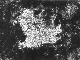
The pattern of cracking indicating expansion of the concrete can be very similar to the cracks generated in masses of mud when the top layer dries and shrinks, plastic shrinkage cracks (see Chapter 4), and the cracks in certain lava flows that occur when the surface cools rapidly and shrinks. Each portion of the surface pulls away from every other portion, generating an irregular honeycomb pattern. The size and regularity of the pattern depend on the cohesiveness, uniformity, and isotropy of the material and the speed of shrinkage (see Fig. 10-1).
This pattern is generated because there is a differential volume change between the exposed surface material and the attached massive substrate. In plastic shrinkage cracking, mud cracking, or cooling lavas, the surface has shrunk relative to the substrate. In expansive alkali-aggregate reactions, the pattern is generated by an increase in volume of the substrate relative to the volume of the overlying surface material. The surface becomes cracked because it is attached to the underlying material. The lower portion of the concrete is damper than the surface portion due to contact with ground water or water vapors rising from the water table and lack of drying by sun and wind. Chemical reactions can take place more readily in the sence of water than in dry zones; therefore, more expansion takes place in the lower portions of the concrete that is reacting by these mechanisms and the surface does not expand. In the early stages of this reaction, the concrete in the lower expanding portions of the placement is squeezed together by the reaction and may not show much cracking. The surface crack pattern has been called pattern cracking, map cracking, Isle-of-Man cracking (see Fig. 10-2), and crows-foot cracking.
In ordinary concrete that is free to expand equally in all directions parallel
to the plane of the surface, the classical cracking pattern is usually very
evident on the surface in all the stages of the deterioration until the concrete
is reduced to a rubble during the last stage. In continuously reinforced HCC
or in concrete units that are much longer than they are wide, the concrete is
not free to expand equally in all directions. In the early stages of the deterioration,
it can expand only at right angles to the length and the cracks will of necessity
be at right angles to the direction of the expansion and therefore parallel
to the long dimension (and the reinforcing steel when present). In the early
stages, longitudinal cracking caused by the
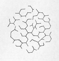
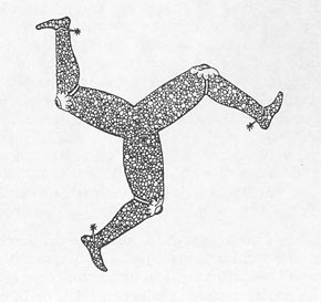
Figure 10-2 SYMBOL FROM COAT OF ARMS OF RULERS OF ISLE OF MAN. This triske lion shows the typical 120° angles of pattern cracking and illustrates why this kind of cracking is sometimes called Isle-of-Man cracking.
alkali-aggregate reactions has often been mistaken for cracking due to expansion of the corrosion products of the reinforcing steel. If a nonreinforced, relatively equant concrete member fabricated with similar materials (such as a bridge approach slab) and placed at the same time is available, it may show the classical pattern cracking long before the longitudinal or reinforced unit exhibits anything other than longitudinal cracking. If a reinforced concrete pavement has deteriorated to the stage of extensive longitudinal cracking, any companion nonreinforced concrete may have deteriorated to a rubble and been replaced long ago. Figures 10-3 and 10-4 show examples of concrete distressed by an alkali-silica reaction.
The expansion of the placement may be very evident. Expansion joints may have closed, with the joint compound having been squeezed out. Guardrail sections that had been planned with a space between may be abutting and grinding together and destroying each other. Occasionally, the expansion may cause blowups, with slabs of the concrete appearing to jump upward because they no longer fit the space. The expansion can cause shearing of bolts and, occasionally, humping of nearby flexible paving on the shoulders (see Figs. 10-5 through 10-7).
If elements of the placement are being forced together or the crack pattern indicates that the lower or damper portions of the concrete may have expanded relative to the upper drier portions or both, the concrete is probably deteriorating by internal expansion.
The expansion is not always clearly shown and may be difficult to understand and document. The expansion is greatest in the areas that have the least optimum combination of factors, that is, the areas that combine the reactive aggregate in sufficient amounts; a sufficient amount of alkali in the cement; and, most variable of all, sufficient amounts of moisture and a sufficiently high permeability to permit the reaction and expansion to occur. Because the reaction cannot occur without moisture, the reaction and expansion are greatest at the depths in the concrete that very seldom become dry. The surface zone of the concrete is the driest portion, does not react as much, and does not expand as much. The surface portion is bonded to the concrete beneath and must move with it. Therefore, it cracks (see Fig. 10-8). An internal RH of 80% is all that is needed for any and all chemical reactions using water to proceed (alkali-silica reaction, cement hydration, etc.). Nearly all concrete will have an internal RH of more than 80% if one side is on the ground and the RH is measured at a depth of 2 in. from the exposed surface-even in the desert (B. Mather, personal communication, October 1991).
10.2.2.3 Aggregate Lithology
By inspection, hardness, and reaction to dilute HCl, a preliminary identification of the major portion of the aggregate as either siliceous or carbonate rock should be made. Certain aggregates may be mixtures of various rock types, and some rocks may be mainly carbonate materials but may contain sufficient highly reactive silica to cause alkali-silica deterioration.
10.2.2.4 Exudations, Coatings, and Pore Fillings
The alkali-silica reaction produces an expansive silica gel that
will be visible on the surface of the concrete in most advanced cases of deterioration.
The gel may be

Figure 10-3 TYPICAL DESTRUCTIVE ALKALI-SILICA REACTION IN PAVEMENT
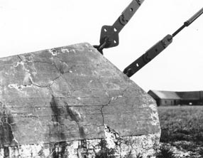
Figure 10-4 DESTRUCTIVE ALKALI-SILICA REACTION IN ANCHOR BLOCK
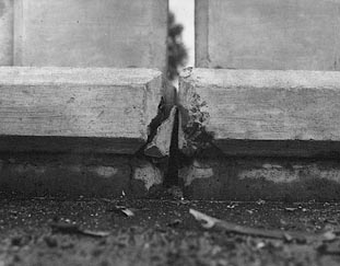
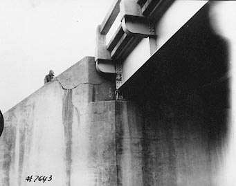
Figure 10-6 UPPER PORTION OF BACK WALL
SHEARED BY EXPANSION OF BRIDGE DECK
 |
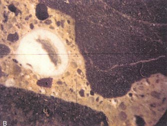 |
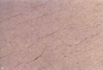
Figure 10-7 DESTRUCTIVE ALKALI-SILICA REACTION IN PAVEMENT. A. Pavement.
B. Alkali-silica gel in a 2-mm void in a lapped slice from the pavement
in A. The dark aggregate is siltstone. (Photographs by M. C. Thomson,
PennDot.)
 |
 |
translucent and moist or sticky but often becomes dehydrated and carbonated to an opaque white coating or an efflorescence (see Figs. 10-9 and 10-10).
Occasionally, as the gel dehydrates on a pavement surface, it becomes polished to a translucent glaze. In a severely deteriorated bridge, the silica gel and leached-out calcareous reaction products may form stalactites hanging under the bridge. In cases of an alkali-silica reaction with little or no deterioration due to expansion, the silica gels may exist within the concrete as pore fillings or as fillings in cracks produced by structural strains or deterioration due to freezing and thawing.
The exudations may be tested for the presence of silica gel by means of the uranyl-acetate test (Stark, 1990). This test is detailed in 10.2.3. It will require a source of electric power and a light-tight viewing box (portable darkroom) for use in an outdoor environment.
If the deterioration is determined to be due to expansion of the concrete of the placement and there is no evidence of alkali-silica gels (even when the HCC is examined in thin section with the petrographic or P/EF microscope), the distress must be due to a cause other than the alkali-silica reaction. If the aggregate is fine-grained limey dolomite, the alkali-carbonate reaction is likely. Discoveries of new reactions will occur only if the petrographer and the client or engineer consider all the facts with an open mind.
If the alkali-silica gels exist and the major portion of the aggregate is carbonate rock, then a sufficient quantity of chert, opal, or other siliceous substance of low crystallity must be present within the carbonate rock as vein fillings, siliceous fossils, or other inclusions.
Sampling of HCC in the early stages of alkali-aggregate deterioration should
be much more complete than the sampling suggested in Appendix B. The surface
evidences of alkali-aggregate reactions are not usually evenly distributed on
the placement and are not often indicative of the condition of the HCC beneath
the surface. Whereas it is important to obtain specimens of the badly deteriorated
areas, it is equally important to study specimens of concrete from areas that
have no surface deterioration so that an assessment of the extent of the underlying
expansion can be made. Full-depth cores should be taken of several areas showing
surface distress, of apparently undamaged HCC halfway between such areas, and
at regular distances between the halfway cores and the most distressed areas.
The laboratory examination can be conducted in three steps as follows:
1. Study cut or cored specimen surfaces and crack surfaces
produced by the reaction (see Chapter 8). By studying the crack structure
and surface of the cracks, provide the client with the reasons this has been
determined to be an expansive reaction rather than plastic shrinkage cracking
(see Chapter 4). Examine the surfaces for the presence of any reaction products
and for the relationship of the cracks in the paste to any deterioration of
the aggregate particles. Place particular emphasis on the specimens of the portion
of the placement that has expanded. The material of the severely cracked drier
surface portion has not expanded so much and may not exhibit so abundantly the
reaction products that cause the expansion
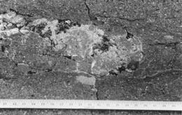
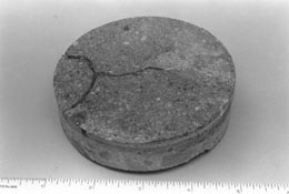
Figure 10-9 ALKALI-SILICA GEL. A. Gel
exuding at deteriorating portion of pavement. B. Gel on surface of core
removed from deteriorating pavement. Notice the 1200 cracking.
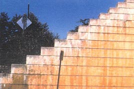
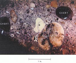
Figure l0-10 ALKALI-SILICA GEL ON BACK WALL. A. Gel on deteriorating back wall. B. An interior surface showing type of aggregates and reaction products of this reaction. G = pocket of alkali-silica gel; arrows indicate gel-filled cracks.
and the deterioration. Study the aggregate altered by the alkali-silica reaction. Many aggregate particles may be seriously deteriorated. Such deterioration may be (1) rims on the aggregate that seem to make the exterior of the aggregate less permeable, (2) gel-filled cracks extending out into the paste, (3) hollowed-out centers or centers of sedimentary particles (e.g., sandstone) that have had the original cement between the sand grains removed by the reaction so that the centers are more friable than the rims, and (4) aggregate particles that have been cracked by deposits of gel and dehydrated gel that occur as rims within and around the particles, often on bedding planes or other partings intrinsic to the aggregate. Report the various types of deterioration observed.
When liquid gels exude onto the surface, saturating the paste, filling the cracks, and oozing from the surfaces or dehydrated, carbonated gels can be seen as a white deposit, the alkali-silica reaction is in its most easily identifiable phase (see Figs. 10-8 through 10-10). These white deposits are common as rims around coarse aggregate in the paste and the cracks and shaley partings in the aggregate and as fillings in voids. These deposits are more common with depth. In the near-surface portions of the concrete, the rims may be difficult to see. The rims that occur inside the aggregate are most easily seen on surfaces that have been forced apart by the reaction, that is, in cracks caused by the reaction (see Fig. 10-10). On the surfaces of cores and on sawed and lapped surfaces, there may be no evidence of rims whatsoever and the only hint of an alkali-silica reaction may be scattered white void fillings of dehydrated silica gel.
The interior of the reacted concrete often ha s large cracks that may be empty because they have been forced apart by expansion elsewhere in the system. The cracks may be filled with alkali-silica gel and other reaction products, such as calcium carbonate and calcium hydroxide.
2. Identify alkali-silica gels in exudations, aggregate rims and cracks, and pore fillings by means of the method using a uranyl-acetate solution and fluorescent light that was well described and illustrated by Stark (1990). The use of this definitive test will vent any confusion between silica gels and deposits of other secondary products, such as calcium carbonate, that might be leached from the concrete. Silica gel is common in all HCC fabricated with a siliceous aggregate. It is not necessarily deleterious. It must cause expansion to cause distress.
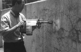
If this test is used, care must be taken to follow all the safety cautions described. A fresh concrete surface free of laitance and carbonation is required. In the laboratory, a fresh surface can be sawed, produced with an electric rotary hammer fitted with a bushing head that looks like a meat tenderizer (see Fig. 10-11), or produced by breaking the specimen with a sledgehammer or in a trimmer (Fig. 2-10). Outdoors on the surface of a placement, the fresh surface can be produced by using a rotary hammer or by sawing or hand hammering off a section of concrete. In the laboratory, the uranyl-acetate-treated specimen is viewed in ultraviolet light in a dark place (closet or darkroom). Outdoors, a light-excluding viewing box (portable darkroom) containing the ultraviolet light is required because the fluorescence of the silica gel that has absorbed the uranium ions is too faint to be seen in daylight.
Any powdered concrete is rinsed from the surface.
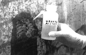
The uranyl-acetate solution is sprayed on the surface (Fig. 10-12), allowed
to react for 5 min, and then rinsed away. The concrete is examined for fluorescent
gel with the ultraviolet light (see Fig. 10-13).
 |
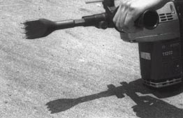 |
Figure 10-11 ELECTRIC HAMMER REMOVING CARBONATED
SURFACE OF HCC.A. Operation of hammer. B. Close-up of bushing
head for electric hammer.
 |
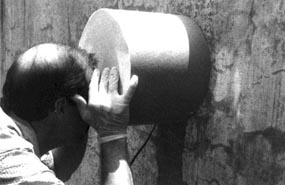 |
Figure 10-12 TESTING FOR ALKALI-SILICA GEL.
A. Spray bottle for applying rinsing water and uranyl-acetate solution.
Notice the gloves used to protect the hands from the uranium-bearing chemical.
B. Dark viewing box. The ultraviolet light is mounted inside the box.
The bottom edge of the box is soft, easily conforms to the concrete surface,
and excludes light. The viewing port is rimmed with a soft dark sponge shaped
to conform to the observer's face.
 |
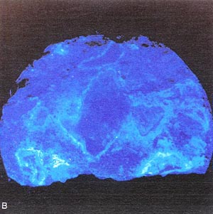 |
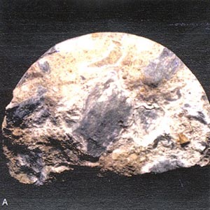
Figure 10-13 SPECIMEN TREATED WITH URANYL-ACETATE
FROM PAVEMENT WITH DESTRUCTIVE ALKALI-SILICA REACTION. A. Ordinary light.
B. Ultraviolet illumination causes silica get to fluoresce. (Darkroom
photograph; exposure 1.5 mm.)
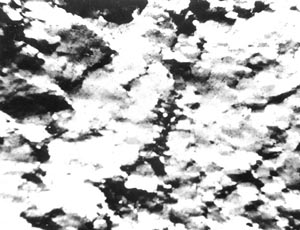
Figure 10-14 THIN SECTION OF HIGHLY STRAINED QUARTZITE. Crossed nicols.
3. Examine a number of finely lapped slices.
Select a variety of aggregate particles for study with the petrographic or P/EF
microscope, and mark the surface of the specimen, usually a lapped surface,
to indicate the location of the desired thin sections. Prepare thin sections
(about 15 um in thickness) of these aggregates and adjacent areas of paste.
Identify the constituents, and determine the structure of the reactive components
by use of the petrographic or P/EF microscope. Report the structure and mineralogic
and lithologic identity of reactive particles to the client.
One of the several kinds of rock that are often subject to this reaction is
shown in thin section in Figure 10-14.
10.2.4 Testing of Siliceous Aggregates
Specimens of aggregate are often submitted to the petrographic laboratory to be tested for suitability for use in HCC. Siliceous aggregates may be tested for potential alkali-silica reactivity. Unfortunately, the test results may not be conclusive. The probability of specific aggregate types taking part in this reaction and causing deterioration in the first few years can generally be ascertained in accordance with ASTM C 227 (mortar-bar method). The ability of the procedures specified in ASTM C 227 to detect the siliceous rocks that react slowly is generally limited by the willingness of the testing technologists to extend the time limits of the test. The time limits prescribed by the test may allow the detection of only aggregates that will show silicate-aggregate reactive symptoms early in the life of the placement, probably within the first year or two. An aggregate that does not cause any deleterious reaction in a placement for the first 6 or 7 years might not expand sufficiently to exhibit its deleterious nature until it has been tested for 3 years or more, if ever.
In recent years, there has been a controversy concerning the proper method of conducting this test. The containers in which the mortar bars are presumably maintained at 100% humidity may or may not have the moisture evenly distributed throughout their height. The method presently requires lining the cans with blotting paper to distribute the humidity; some researchers have stated that the blotting paper causes dripping on the specimens and leaching of the alkalies from the paste (Rogers & Hooton, 1991). If the alkalies are thus leached out, they are not available for reaction in the mortar bars and the expansion is less. Alkali ions have been found in the fluid at the bottom of the containers. For these reasons, this test has been conducted with many different arrangements of mortar bars and blotting paper, but no one way has, over time, remained the accepted standard method.
Regardless of the leaching difficulties, the test specified in ASTM C 227 is the type of test for alkali-silica reactivity favored by many concrete technologists because the test (or modified versions of the test) can be used to predict the possibility of the expansive alkali reactions occurring in specific cement-aggregate combinations. Thus, if the test performs as it should (it does not with some aggregates), an aggregate can be tested with cements of several different alkali contents and decisions can be made concerning the most cost-effective solution to the problem of deciding which materials to use for a proposed placement.
Because of the problems encountered in the leaching of the alkalies out of the specimen and because of the long time involved in obtaining results in the case of the slowly reacting aggregates, certain other test procedures have been devised. The test that is thought to show the most promise is ASTM C-9, Proposal P 214. This test has not been formally accepted by ASTM; it is undergoing extensive experimental use. The results to date, when compared to the recommended criteria, indicate that this test can (with certain aggregates) generate data that seem to be in conflict with field performance and commonly accepted knowledge concerning the alkali- silica reaction (D. S. Lane & H. C. Ozyildirim, personal communication, October 1991). The test is a rapidly reacting test, and even slowly reacting aggregates can demonstrate their deleterious nature in a few months. Because this test requires that the mortar-bar specimens be placed in a 1 normal solution of NaOH during the reactive period, it has the disadvantage that specific cement aggregate combinations cannot be tested. It is a test for only the reactivity of the aggregate.
10.3 ALKALI-CARBONATE REACTION
The alkali-carbonate reaction was first observed by Swenson (1957) in Kingston, Ontario, Canada, and found by Newlon and Sherwood (1962) to occur in Virginia. This reaction occurs between certain impure dolomitic limestones of a specific petrographic type (Newlon, Sherwood, & Ozol, 1972; Swenson, 1957; Swenson & Gillot, 1960; H. N. Walker, 1978) and the hydroxide ions associated with the dissolved salts of sodium and potassium alkalies that may be found in the cement paste.
The alkali-carbonate reaction is not so well understood as is the alkali-silica reaction. The expansion produced occurs within the aggregate particle. The expansion causes cracks within the aggregate and the paste and therefore deleterious expansion of the mass. The dolomite crystals in the aggregate are chemically altered by the alkali solutions in what is apparently a multistep process. Which step causes the expansion has not been determined.
All known reactive carbonate rocks are from the geologic time period known as the Ordovician period. Fortunately, the particular proportion of minerals and microstructure of the reactive carbonate rock involved are not very common. This rock has been suspected of not being a geologically stable combination of minerals (Steidtmann, 1917). Theoretically, one might say that it is reactive because it is not stable.
The carbonate aggregate that is associated with this reaction is an impure dolomitic limestone. The two major carbonate minerals, calcite and dolomite, are sent in nearly equal amounts. Noncarbonate minerals (insoluble in weak HCl), usually of submicroscopic size, make up 10% to 25% of the mass and generally consist of clay, various iron sulfides, and quartz. Small quantities of other minerals may also be sent. The aggregate is often (not always) dark gray or nearly black because of the finely divided iron sulfides. The texture in a hand specimen is subconchoidal because the individual crystals are so small and interwoven that their cleavage and parting do not affect the surface.
When the weight percentage of Na2O plus 0.658% of the weight percentage K2O is less than 0.45% of the weight of the cement, the cement has been considered to be too low in alkali content to contribute to a significant chemical reaction and concomitant expansion due to the alkali-carbonate reaction (Swenson & Gillott, 1960). At the sent time, we do not know if this low limit for the alkali content will vent the alkali-carbonate reaction in every case.
The alkali-carbonate reaction does not appear to be related to the reaction found in the Midwest that has been termed D-cracking. D-cracking has not been found in Virginia, and therefore VTRC has not had any experience with it. Refer to Appendix E for more details on D-cracking.
The field procedures listed in 10.2.2 should be followed. Figures 10-15 through 10-17 are photographs of deterioration caused by the alkali-carbonate reaction.
The petrographer should ascertain if the coarse aggregate is
a carbonate rock. If any silica-gel exudations, coatings, or pore fillings are
observed, the expansive distress may be partially or completely due to an alkali-silica
reaction despite the fact that the aggregate rock is dominantly a carbonate.
If exudations, coatings, or pore fillings exist in an alkali reaction with a
dolomitic limestone, the dolomitic limestone will be found to contain a large
quantity of poorly crystalized siliceous material and should be tested as a
siliceous aggregate.
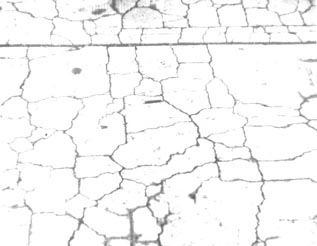
Figure 10-15 DESTRUCTIVE ALKALI-CARBONATE REACTION IN WALKWAY
PAVEMENT. In Kingston, Ontario, Canada.
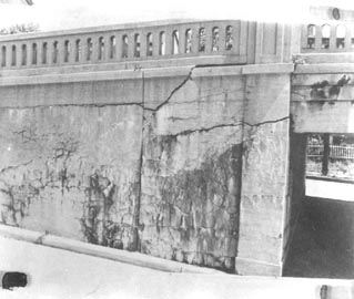
Figure 10-16 DETERIORATION DUE TO A COMBINATION
ALKALI-SILICA REACTION AND ALKALI-CARBONATE REACTION. In New Jersey.
 |
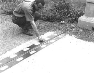 |
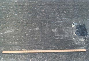
Figure 10-17 DESTRUCTIVE ALKALI-CARBONATE REACTION IN BRIDGE DECK. Near Harrisonburg, Virginia. A Expansive acking of bridge deck. B. Complete closure of joint
The laboratory examination can be conducted in three steps, as follows:
1. Study cut or cored specimen surfaces and crack surfaces produced by the reaction (see Chapter 8). By studying the crack structure and surface of the cracks, provide the client with the reasons this has been determined to be an expansive reaction rather than plastic shrinkage cracking (see Chapter 4). Examine the surfaces for the sence of any reaction products and the relationship of the cracks in the paste to any deterioration of the aggregate particles. If any silica-gel deposits are found, the expansion may be due to the alkali-silica reaction and the procedures and tests used should include those scribed for siliceous aggregates. Place particular emphasis on the specimens of the portion of the placement that has expanded. The severely cracked surface portion has not expanded as much and may not exhibit any deterioration of the aggregate. The deeper portions will have more deteriorated aggregate even though it is not necessarily cracked as much. The signs indicating alkali-carbonate reactivity can be very subtle because the reaction does not cause the growth or exudation of any characteristic reaction products, such as the gel associated with alkali-silica reactions.
Very fine cracks in the aggregate are often found in the portion
of the placement affected by the expansion of the alkali-carbonate reaction.
These cracks may extend into the paste. They may be randomly oriented but may
sometimes occur just under the surface of the aggregate as if a thin layer of
the aggregate was about to pop off (see Fig. 10-18). Cross sections of elongated
or flat particles affected by the reaction may show one or more lengthwise fine
cracks nearly centered in the particle. It may be impossible to find any signs
of deterioration in the aggregate
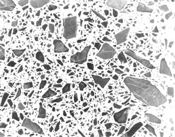
Figure 10-18 FINE CRACKS IN REACTIVE CARBONATE AGGREGATE IN MORTAR BAR WITH HIGH-ALKALI CEMENT. Although the expansion of the mortar bar was negligible, these cracks are typical of those that may be found in specimens that reacted in service.
particles in the less reacted, drier, but more heavily cracked portion of the placement.
2. Examine several finely lapped slices. Study the slices with the stereomicroscope, and select several paste areas and numerous aggregate particles for the production of thin sections and detailed study with the petrographic microscope. Prepare thin sections of the aggregate as detailed in 5.3.2.
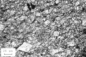
The most easily detected identifying characteristic of the alkali-reactive carbonate rocks is the microtexture of the aggregate. Invariably, this texture is that of small rhombic crystals of dolomite suspended in a calcite, micrite matrix that contains the fine, particulate, insoluble constituents. This texture may occur evenly throughout the aggregate or may be confined to certain seams and crack fillings. All occurrences of carbonate rock that have been found to be reactive have portions in which this particular texture exists. However, not all dolomitic limestones with this texture expand with sufficient force to cause distress.
If the dolomite rhombs are large enough, they may in some cases be observed with hand lens or stereomicroscope on a lightly etched, finely lapped surface of the aggregate. This surface may be fabricated on a large fragment (e.g., 3 by 4 in.) of the rock or may be a lapped surface produced on a slice of the HCC.
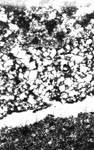
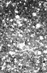
3. Examine thin sections with the petrographic microscope. The dolomite crystals in these reactive rocks are often no more than 10 µm in any direction, and observation of them often requires that the thin section be, at least in part, much thinner than an ordinary thin section for ordinary geologic procedures (see 5.3.2). The texture of the micrite itself is often hidden by the dark murky pall caused by the finely divided insoluble constituents. When the individual grains of the micrite can be discerned, they can be seen to be completely anhedral and tightly locked together, sometimes interlocked in the fashion of the curved seams of the leather cover on a baseball. Sometimes, the dark, greasy looking murk collects into thin, darker brown or black stringers that wind along the contacts of the other constituents. Figure 10-19 shows examples of the microtexture of alkali-reactive carbonate rocks. Figure 10-20 shows similar sections of nonreactive carbonate rocks.
When the alkali-expansive carbonate rocks are used with high-alkali cement, thin sections of the reacted material show definite changes in the microstructure of the aggregate. Many of the euhedral dolomite crystals have been altered. Sometimes, the dolomite has been altered to calcite. Sometimes, the dolomite crystals are partially or completely gone and only a hole the shape of the crystal remains (see Fig. 10-21).
Reactive carbonate rock has been tested in other chemical solutions
that occur in HCC (Walker, 1979b). The most startling results were obtained
with a solution of sodium and calcium carbonates (see Fig. 10-22).
 |
 |
 |
 |
Figure 10-19 ALKALI-REACTIVE MICROTEXTURE IN FOUR CARBONATE ROCKS
 |
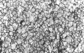 |
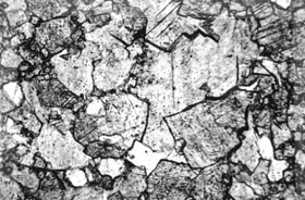
Figure 10-20 NONREACTIVE MICROTEXTURES
OF CARBONATE ROCKS. Examples are shown to illustrate the difference between
these crystalline textures and the partially crystalline reactive textures
shown in Figure 10-19.
 |
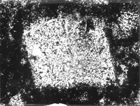 |
Figure 10-21 REACTED DOLOMITE CRYSTAL. A.
Rhombic shape of an unusually large dolomite crystal in very dark micrite
viewed with plane polarized light (from very reactive carbonate aggregate
tested in accordance with ASTM C 586). B. Same view as A
with crossed nicols. Notice that a portion of the crystal has been dissolved
away. The intense birefringence of calcite and dolomite would ensure the detection
of these minerals.
 |
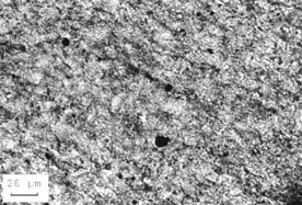 |
Figure 10-22 REACTION OF DOLOMITIC ROCK. A. Microstructure of a reactive dolomitic rock before soaking in a solution of sodium and calcium carbonates. B. Microstructure after test. Notice the destruction of the rhombic structures. The rock has been altered to a fine-grained mixture of calcite and dolomite.
10.3.4 Testing of Carbonate Aggregate
Specimens of aggregate are often submitted to the petrographic laboratory to be tested for suitability for use in HCC. Carbonate aggregates may be tested for potential alkali-carbonate reactivity. This testing is performed in the following three steps:
1. Examine numerous thin sections of the aggregate with the petrographic microscope. Because all reactive carbonate rocks have the distinctive microtexture described, the most efficient procedure is to examine for the texture. Such an examination requires no reaction time or special storage space. If the texture is found, the aggregate is to be considered potentially reactive. If the texture is not sent, the aggregate is not considered alkali-carbonate reactive. If placements fabricated with this aggregate exhibit expansion, the aggregate may not have been properly sampled or the cause of the expansion may be an alkali-silica reaction.
2. Test aggregates considered to be potentially reactive in accordance with ASTM C 586 (rock cylinder method). This is the most rapid method of testing carbonate aggregates for alkali reactivity. It requires less storage space, less fabrication time, and less reaction time than any other test. If the aggregate shows no significant expansion, it is considered nonreactive. Only the potential for deleterious reactivity is determined because the expansion in the aggregate does not necessarily indicate that the expansion is powerful enough to disrupt concrete (Hilton, 1974). The method in ASTM C 227 cannot be used to test carbonate aggregate for reactivity because it requires that the aggregate be crushed to a small size (for use in mortar bars) and the larger size alkali-carbonate reactive aggregate is often more expansively deleterious than the smaller size (Newlon, Sherwood, Ozol, 1972).
3. Test aggregates considered to be potentially reactive by reason of their expansion in accordance with ASTM C 1105 (concrete beam length change due to alkali-carbonate reaction). This test will detect most expansion caused by carbonate-reactive aggregate. Much instructive information concerning the testing of carbonate aggregate may be found in Newlon, Sherwood, and Ozol (1972). Recognize that HCC placements that either have been allowed to dry and kept dry or have such an impermeable structure that water cannot circulate within the concrete will probably show no reaction or distress regardless of the results of any testing regime.

