U.S. Department of Transportation
Federal Highway Administration
1200 New Jersey Avenue, SE
Washington, DC 20590
202-366-4000
Federal Highway Administration Research and Technology
Coordinating, Developing, and Delivering Highway Transportation Innovations
 |
| This report is an archived publication and may contain dated technical, contact, and link information |
|
Federal Highway Administration > Publications > Research > Structures > A Laboratory and Field Study of Composite Piles for Bridge Substructures |
Publication Number: FHWA-HRT-04-043 |
Previous | Table of Contents | Next
This chapter presents the general background of composite piles and a literature review, with specific focus on the two types of composite piles selected for this research: concrete-filled FRP composite piles and steel-reinforced recycled plastic composite piles.
Composite piles refer to alternative pile foundations which make use of FRPs, recycled plastics, and other materials to replace and/or protect steel or concrete, with the intent to produce piles that have lower maintenance costs and longer service lives than conventional piles, especially when used in marine applications and other corrosive environments. Examples of deteriorated conventional piles are shown in figure 1.
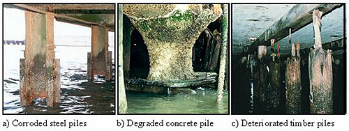
Figure 1. Photos. Degradation of conventional piles
(Iskander and Hassan 1998).
Composite piles were first used in the United States in the late 1980s as replacements for timber fender piles at the Port of Los Angeles (Heinz 1993). The first composite pile prototype was driven in 1987 and consisted of a composite steel pipe encased by recycled plastic (Horeczko 1995). Since the first composite pile application in 1987, several other projects have used composite piles. A list of selected projects where composite piles have been used is presented in table 1. As shown in the table, and reported by Iskander, et al., (2001), composite piles have been primarily used as marine fender piles, as load-bearing piles for light structures, and as experimental test piles.
Several composite pile products are available in the market today, such as steel pipe core piles, structurally reinforced plastic matrix piles, concrete-filled FRP pipe piles, fiberglass pultruded piles, and plastic lumber piles. Of these five pile types, the first three are considered to be better suited for load-bearing applications (Lampo, et al., 1998). These three pile types are shown in figure 2.
Figure 2. Illustration. Common types of composite
piles.
The following subsections describe these three load-bearing composite pile candidates in more detail.
This pile consists of a recycled plastic shell with a steel pipe core interior, as shown in figure 2a. This pile may be obtained in diameters ranging from 8 to 24 inches (20.3 to 61.0 cm) and up to 75 feet (22.9 m) in length (Plastic Pilings 2001). The steel pipe core ranges from 4 to 16 inches (10.2 to 40.6 cm) outer diameter, with pipe wall thicknesses between 6 to 40 millimeters (0.236 to 1.57 inches) (Plastic Pilings 2001).
|
Site |
Year |
Application |
Pile Manufacturer |
Pile Type |
Source |
|---|---|---|---|---|---|
|
Port of Los Angeles, CA |
1987 |
Fender piles |
Plastic Pilings, Inc. |
Steel pipe with thick plastic shell |
Heinz (1993), Hoy (1995) |
|
1991-5 |
Fender piles |
Plastic Pilings, Inc.; Seaward International, Inc.; Hammer's Plastic Recycling |
Plastic piling with steel core |
||
|
Port of NJ, Newark, NJ |
1991 |
Fender piles |
Plastic Pilings, Inc. |
Steel pipe with thick plastic shell |
Hoy (1995) |
|
Naval Station Roosevelt Roads, Puerto Rico |
1991 |
Trial fender piles |
Plastic Pilings, Inc. |
Steel pipe with thick plastic shell |
Hoy (1995) |
|
Port of Grays Harbor, Aberdeen, WA |
1992-3 |
Fender piles |
Plastic Pilings, Inc. |
Steel pipe with thick plastic shell |
Hoy (1995) |
|
Port of Seattle, WA |
1993 |
Fender piles |
Plastic Pilings, Inc. |
Steel pipe with thick plastic shell |
Hoy (1995) |
|
Port of Oakland, CA |
1993 |
Fender piles |
Plastic Pilings, Inc. |
Steel pipe with thick plastic shell |
Hoy (1995) |
|
Pearl Harbor, HI |
1994 |
Fender piles |
Plastic Pilings, Inc. |
Steel pipe with thick plastic shell |
Hoy (1995) |
|
Port of NY/NJ |
1994 |
Fender piles |
Seaward International, Inc. |
Recycled plastic with fiberglass reinforcing |
Hoy (1995) |
|
Creative Pultrusions, Inc. |
Ultra high molecular weight polyethylene |
||||
|
Pier Bravo, NAS North Island, San Diego, CA |
1995 |
Fender piles |
Plastic Pilings, Inc. |
Recycled plastic reinforced with welded steel rebar cage |
Tetra Tech EM, Inc. (1999) |
|
Delaware Bay, DE |
1996 |
Fender piles |
Hardcore Composites |
Fiberglass shell filled with concrete |
Phair (1997) |
|
Port of New Orleans, LA |
1996 |
Fender piles |
Seaward International, Inc. |
Recycled plastic with fiberglass reinforcing |
Eustis Engineering Co, Inc. (1996) |
|
Pier 16-Naval Amphibious Base Coronado, San Diego, CA |
1996 |
Fender piles |
Plastic Pilings, Inc. |
Recycled plastic reinforced with welded steel rebar cage |
Tetra Tech EM, Inc. (1999) |
|
US Navy EMR Facility Pier Ingleside, TX |
1997 |
Pier piles |
Lancaster Composites |
FRP shell with concrete core |
Stapleman (1997) |
|
Pier 23, Norfolk, VA |
1997 |
Fender piles |
Lancaster Composites |
FRP shell with concrete core |
Lancaster (2000) |
The steel core provides the structural strength while the plastic shell protects the pile from degradation. The plastic shell can be omitted below the portion of the pile exposed to water (Plastic Pilings 2001). If the plastic shell is used only in the upper portion of the pile that is exposed to water, the design procedure for this pile would be essentially the same as for a conventional steel pipe pile. The plastic shell does not come into play structurally, since its only function is to protect the steel pipe along the exposed portion of the pile. Since the design procedure of steel pipe piles is well established, it was decided that there was relatively little need for further research on this kind of pile.
This composite pile consists of a recycled plastic matrix structurally reinforced with FRP rods or a welded steel rebar cage. The typical configuration of this type of pile is shown in figure 2b. An attractive feature of this pile is that when reinforced with FRP rods, the pile is nonmagnetic and 100 percent recyclable (Lindsay 1996). This environmentally friendly composite pile type uses approximately 240 recycled 1-gallon (3.79-L) milk jugs per linear foot (0.305 m) of a 12-inch (0.305-m) nominal diameter pile (Taylor 1995). The piles are commercially available in diameters ranging from 8 to 24 inches (0.203 to 0.610 m), and are reinforced with 6 to 24 FRP or steel reinforcing rods, which range between 0.75 to 1.41 inches (1.91 to 3.58 cm) in diameter (Plastic Pilings 2001, Seaward International 2001).
These piles are produced by a continuous extrusion process that enables the production of continuous pile of virtually any length (Lindsay 1996, Taylor 1995). This continuous length precludes design problems inherent in segmented piles (Horeczko 1995). To enhance durability, the plastic matrix is chemically treated with antioxidants and ultraviolet (UV) inhibitors that retard the effects of UV light on plastic (Taylor 1995, Iskander and Hassan 1998).
To date, these piles have been used primarily as fender piles in several naval facilities (Hoy 1995). Lindsay (1996) reported preliminary tests on 12-inch (0.305 m) diameter, 60-ft (18.3 m) long piles. The results indicated the piles could carry axial working loads of up to 10 tons (89 kN) and 20 tons (178 kN) per pile when reinforced with FRP and steel rods, respectively. Some potential problems associated with these piles include the possibility of debonding of the reinforcing FRP rods and the potential for high creep rates associated with the high polymeric content of these piles. One version of this pile is structurally reinforced with a reinforcement cage with the rebars welded to a continuous steel spiral. This version of the pile is reported not to have the aforementioned problems (Plastic Pilings 2001).
Although this type of composite pile is considered to have potential for load-bearing applications, it was not initially selected for the second phase of the project due to budget limitations. The late withdrawal of one of the pile manufacturers allowed inclusion of this pile at the last minute.
In a concrete-filled FRP composite pile there are two main structural components: an FRP shell or tube, and a concrete infill without steel reinforcement. The FRP shell provides, among other things, a stay-in-place concrete form, confinement to the concrete, tensile reinforcement, and corrosion protection (Fam and Rizkalla 2001a, b). The concrete infill provides compressive load capacity. The two main manufacturers of this type of pile in the United States are Hardcore Composites and Lancaster Composite (Iskander, et al., 2001).
Hardcore piles can be installed by driving the empty FRP shell and then filling it with concrete, although they are also installed by filling with concrete and then driving after the concrete has cured (Hardcore Composites 2001). Lancaster Composite's piles are sold under the commercial name CP40, and are filled with concrete and allowed to cure prior to driving (Stapleman 1997, Lancaster Composite 2000).
The FRP shells used by Hardcore Composites are fabricated using a vacuum-assisted resin transfer molding process (VARTM), while Lancaster Composite's FRP shells are made using a filament winding technique. Typically, both piles are available in diameters ranging from 8 to 24 inches (0.203 to 0.610 m), with wall thicknesses ranging between 0.18 to 0.36 inches (0.46 to 0.91 cm). Both manufacturers have the flexibility to modify the FRP composite shell laminate architecture (including number of layers, fiber orientation, and resin and fiber types) to better suit the load demands of a specific project. These piles can be produced in virtually any length (Lancaster Composite 2000, Hardcore Composites 2001).
This type of composite pile was considered to have good potential for load-bearing applications, hence it was selected for the second phase of the research project.
The initial research plan entailed focusing the study on concrete-filled composite piles, which were selected after the initial pile screening phase. The piles were to be manufactured by Lancaster Composite, Inc., and Hardcore Composites. The late withdrawal of Lancaster Composite, Inc. allowed the inclusion of a recycled plastic composite pile manufactured by Plastic Pilings, Inc. Information available for concrete-filled FRP composite piles and steel-reinforced recycled plastic composite piles is presented in the following subsections.
Considerable effort has been expended to research the structural behavior of concrete-filled FRP composite tube piles (e.g., Lampo, et al., 1998, Samaan, et al., 1998, Mirmiran, et al., 1999, Fam 2000, Fam and Rizkalla 2001a, b, Mirmiran, et al., 2001, Moran and Pantelides 2002a, Becque, et al., 2003). Relevant findings from selected research studies are described in the following subsections.
The structural behavior of concrete-filled FRP composite tubes under axial compression has been studied extensively and several analytical models have been proposed to predict their response. Table 2 lists these models.
|
Author |
Type of Confinement |
Ultimate Strength fcc |
Ultimate Axial Strain ecc |
|---|---|---|---|
|
Fardis and Khalili (1981) |
GFRP-encased concrete |
 |
 |
|
Karbahari and Eckel (1993) |
FRP-encased concrete |
 |
 |
|
Mirmiran and Shahawy (1997)* |
GFRP-encased concrete |
- |
|
|
Miyauchi, et al. (1997)** |
CFRP-wrapped concrete |
 |
 |
|
Samaan, et al. (1998)* |
GFRP-encased concrete |
 |
|
|
Saafi, et al. (1999) |
CFRP and CFRP encased concrete |
 |
 |
|
Toutanji (1999) |
CFRP and GFRP wrapped concrete |
 |
 |
|
Spoelstra and Monti (1999) |
CFRP and GFRP-wrapped and encased concrete |
 |
 |
Notes: * units are in MPa, ** Equation for ![]() cc is valid for
fco = 30 MPa
cc is valid for
fco = 30 MPa
CFRP = Carbon fiber-reinforced polymer, GFRP = Glass fiber-reinforced polymer,
fco = compressive strength of unconfined
concrete, ![]() co = ultimate strain
of unconfined concrete,
co = ultimate strain
of unconfined concrete,
Ef = Hoop modulus of elasticity of FRP tube, ff = Hoop tensile strength of FRP tube,
fl = lateral confining stress, tf = thickness of FRP tube, D = diameter of concrete core.
Recently, other models have been proposed by Fam (2000), Fam and Rizkalla (2001a, b), Moran and Pantelides (2002b), Shehata, et al. (2002), and Becque, et al. (2003). Most of these models build upon the simple observation that the typical stress-strain curve of concrete-filled FRP composite columns has an approximately bilinear shape, as shown in figure 3.
Figure 3. Graph and Photos. Confinement effect of FRB tube
on concrete (Fam and Rizkalla 2001a, b).
As shown in figure 3, the FRP tube of a composite pile contributes structurally to the pile by resisting some of the axial load, and by providing confinement to the concrete core. The beneficial effect of confinement on the total load-carrying capacity of a short, concrete-filled FRP tubular element was studied by Fam and Rizkalla (2001a). As illustrated in figure 3, the capacity of the composite stub significantly exceeds the load- sharing capacity of the two individual materials (Fam and Rizkalla 2001a). The load-strain curve starts to depart from the unconfined concrete curve in the vicinity of the unconfined concrete strength. As this stress level is approached, the concrete core starts to experience significant microcracking as well as increased lateral expansion. In response to the lateral expansion of the concrete, the FRP shell applies a radial confining pressure, which continuously increases due to its linear elastic properties (Fam 2000). The second slope of the load-strain curve is a function of the hoop tensile stiffness of the FRP shell, and the ultimate peak strength is governed by the hoop tensile strength of the FRP shell. A more detailed description of the behavior of concrete-filled FRP tubes under axial compression loading can be found in Fam and Rizkalla (2001a, b).
The short-term axial capacity of a concrete-filled FRP tube can be predicted using a confinement model such as the one proposed by Fam and Rizkalla (2001b). This model is an incremental variable confinement model that satisfies equilibrium and radial displacement compatibility between the concrete core and the FRP tube, and it makes use of the constant confinement model of Mander, et al. (1988).
The radial confinement pressure applied by the FRP shell can be
obtained from equilibrium and by imposing radial displacement
compatibility between the concrete core and the FRP shell. When
both the concrete core and FRP shell are axially loaded with the
same strain level (![]() cc), the
radial confinement pressure (
cc), the
radial confinement pressure (![]() R) can be estimated as follows (Fam
2000):
R) can be estimated as follows (Fam
2000):
 (1)
(1)
where
The variable radial confining pressure is obtained from equation 1 by using the secant elastic modulus and the secant Poisson's ratio of the concrete as a function of axial strain level.
The model relates the axial stress of the confined concrete core
(fcc), at any given axial strain level
(![]() cc), to the peak confined
strength of the concrete (f’cc) as follows:
cc), to the peak confined
strength of the concrete (f’cc) as follows:
![]() (2)
(2)
where
![]() (3)
(3)
and where
The peak confined strength (f cc) can be estimated using the following expression proposed by Mander, et al. (1988):
 (4)
(4)
The load-strain response, predicted using the model shown above, and the experimental load-strain behavior obtained for Test Stub No. 1 (from Fam and Rizkalla 2001a), are shown in figure 4. The figure shows good agreement between the model and the experimental results.
Figure 4. Graph. Experimental versus predicted load-strain
behavior using Fam and Rizkalla's model.
This model will be used later in chapter 4 to illustrate the influence that the degradation of the hoop properties (stiffness and strength) of FRP tube has on the long-term axial capacity of concrete-filled tubular FRP piles.
Research on the flexural behavior of concrete-filled FRP circular tubes includes studies by Mirmiran (1999), Fam (2000), Mirmiran, et al. (2000), Fam and Rizkalla (2000), Mirmiran, et al. (2001), and Fam and Rizkalla (2002). These structural elements can be used to resist bending moments, but the benefits of concrete confinement are less in bending than the purely axial loading case (Fam 2000). In flexure, the FRP tube acts as a noncorrosive reinforcement, while the concrete provides the internal resistance force in the compression zone and increases the stiffness of the member (Fam and Rizkalla 2002). The concrete core also prevents local buckling of the FRP tube.
A comprehensive experimental program to study the short-term flexural behavior and failure modes of concrete-filled FRP tubes was recently completed by Fam and Rizkalla (2002). Their study showed that the flexural behavior is highly dependent on the stiffness and diameter-to-thickness ratio of the FRP tube, and to a lesser extent on the concrete strength. The study also showed that, in general, the cracking moment resistance is relatively small compared to the ultimate moment capacity
The short-term flexural capacity of a concrete-filled FRP tube can be predicted using a strain compatibility/equilibrium model such as the one proposed by Mirmiran and Shahawy (1996) or Fam (2000). The methodology assumes that sections normal to the neutral axis remain plane after bending, and that the FRP shell is perfectly bonded to the concrete interior (i.e., a linear strain distribution through the cross section). The method consists in discretizing the pile cross section into a series of strip elements for integrating the normal stresses over the cross-sectional area. The discretization results in both FRP and concrete strip elements, as shown in figure 5. The stress integration is done by assigning the appropriate constitutive model for each material. Details of the development of the model and its validation through experimental results can be found in Fam (2000) and Fam and Rizkalla (2002).
Figure 5. Illustration. Strip elements for sectional
analysis (Mirmiran and Shahawy 1996).
The load-curvature response, predicted using the model just described, and the experimental load-strain behavior for Beams 4 and 13 from Fam and Rizkalla (2002), are shown in figure 6. The figure shows good agreement between the model and the experimental results, especially when accounting for tension stiffening.
Figure 6. Graphs. Experimental versus analytical
moment-curvature response (adapted from Fam and Rizkalla
2002).
This model will be used later in chapter 4 to illustrate the influence that the degradation of the FRP tube properties (stiffness and strength) has on the long-term axial capacity of concrete-filled tubular FRP piles.
Mirmiran and Shahawy (1999) performed a detailed study on concrete-filled FRP tubes under various combinations of axial and flexural loads. Two types of FRP tubes were used to simulate the conditions of overreinforcement (where compression failure governs) and underreinforcement (where tension failure governs). The overreinforced specimens were prepared using tubes 348 mm (13.7 inches) in diameter with a wall thickness of 14 mm (0.551 inches), while the underreinforced specimens used 369-mm (14.5-inch) tubes with a 6-mm (0.236-inch) wall thickness. The reinforcement ratios (ratio of area of FRP shell to area of concrete core) for the over-and underreinforced concrete-filled tubes were 18.27 and 7.56 percent, respectively. Since the strength of the FRP tubes differed in these specimens, the authors proposed the use of a reinforcement index, defined as the reinforcement ratio multiplied by the ratio of the axial tensile strength of the FRP tube to the concrete compressive strength. The reinforcement indices of the over- and underreinforced sections were 3.39 and 0.19, respectively. The interaction diagrams for the two types of specimens are shown in figure 7.
Figure 7. Graph. Interaction diagrams, concrete-filled FRP
tubes (Mirmiran 1999).
The overreinforced specimens were found to behave better as beam columns. They deflected to a lesser extent (ultimate deflections of the overreinforced specimens were about 25 to 50 percent lower than the underreinforced specimens), and failed at much higher bending moments. Failure of the overreinforced specimens while in compression was considered to be gradual or ductile. The underreinforced failure mode was brittle and sudden. Based on this study, the authors concluded that concrete-filled FRP tubes could be used for beam-column applications, and recommended the use of overreinforced specimens. Test observations also indicated that bond failure or slippage in beam columns is not as significant as in beam specimens (pure flexure), as long as the end connections are designed properly. For beam specimens, shear transfer mechanisms such as internal ribs or treatments of the inner surface of the tubes were recommended to enhance the composite action between the FRP shell and the concrete core.
Design of concrete-filled FRP tubes for this type of loading can be done using the same sectional analysis as described in section 2.3.1.1.2 for pure flexure. This analysis methodology can be easily programmed and used to generate moment-curvature and interaction diagrams. A more detailed description of the methodology can be found in Mirmiran and Shahawy (1996), Mirmiran (1999), and Fam (2000).
Research on the structural behavior of steel-reinforced recycled plastic piles is notably absent in published literature. Information about the performance of these piles is limited to reports commissioned by pile manufacturers. Table 3 lists the available structural information from the manufacturer. This information consists of test results, and it does not include design methods.
|
Type of test |
Source |
|---|---|
|
Three-point bend test |
Asaro (2000) |
|
Limited flexural tests |
Warren (1996) |
|
Axial compression test |
Stokes (2002) |
Iskander, et al. (2003), studied the compressive strength of the plastic material used for these kinds of piles. The results showed a marked nonlinear behavior and significant spatial distribution of strength and density within the specimens. However, the results from tests shown in table 3 indicate that the majority of the structural capacity and stiffness comes from the welded steel rebar cage.
The lack of long-term performance and durability data on composite piles is a concern (Lampo, et al., 1998, Iskander and Hassan 1998, Iskander, et al., 2001). There is an urgent need for research in this area.
The principal mechanisms for degradation of the FRP composites used in piles are moisture absorption over time and freeze-thaw cycles. Chemical degradation and UV radiation also affect long-term durability, but to a lesser extent. Furthermore, UV degradation resistance of most composites is improved by applying protective coats and additives during the manufacturing process. The degradation mechanisms related to moisture absorption and freeze-thaw cycles are discussed below.
Degradation due to moisture absorption may significantly reduce the life of FRP composites (Garcia, et al., 1998). Absorbed moisture can cause pronounced changes in modulus, strength, and strain to failure (Springer, et al., 1980). The moisture content of submerged FRP composites increases through diffusion. The absorbed moisture can act as a plasticizer of the composite resin, and can cause matrix cracking, fiber-matrix debonding, and corrosion of glass fibers (stress corrosion) (Garcia, et al., 1998). These effects result in a reduction of strength and stiffness of the FRP composite. For example, Schulheisz, et al. (1997), recorded strength and stiffness reductions on the order of 20 percent and 5 percent, respectively, for E-glass/vinyl ester composites submerged in 25 oC (77 oF) water for a period of 200 days. The implications of such strength and stiffness reductions on the design of composite piles can be significant.
In addition to submergence time, temperature and stress level also influence the amount of moisture that FRP will absorb while submerged. An FRP composite subject to tensile stresses is expected to have a faster rate of moisture absorption. Figure 8 shows schematically how time and temperature influence moisture absorption, how moisture absorption degrades property values, and how exposure time thus produces a reduction in property values. Evidence of the existence of damage to FRP composites after submergence in water is illustrated in the scanning electron microscope (SEM) images shown in figure 9. The SEM image of the submerged sample shows fiber damage and crack formation at the fiber-matrix interface (McBagonluri, et al., 2000).
Figure 8. Graphs. Moisture absorption-related durability
model.
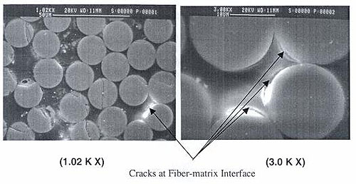
Figure 9. Images. SEM images showing FRP damage
(McBagonluri, et al., 2000).
Freeze-thaw cycles can also degrade FRP composites. Freeze-thaw cycles cause the volume of absorbed water to increase. Such volume changes lead to crack propagation and damage to FRP (Verghese, et al., 1999).
Iskander and Hassan (2001) carried out an accelerated degradation study on the recycled plastic material used in the plastic piling manufactured by Seaward International. Their study involved compression tests on coupon samples submerged in aqueous solutions with pH ranging between 2 and 12. A 25 percent loss in compressive resistance was predicted to take place after a 21-year exposure to the types of aqueous solutions used.
The durability of steel-reinforced plastic piles installed at Pier Bravo in NAS North Island, San Diego, CA was evaluated in 1999. The piles were manufactured by Plastic Pilings, Inc. and were installed in December 1995. Inspections carried out 3.5 years after installation showed no significant degradation.
There has been little research to date on geotechnical issues related to either concrete-filled FRP composite or steel-reinforced recycled plastic piles. Some important issues are pile driveability, lateral load capacity, and axial load capacity. These issues are discussed in the following subsections.
To date, very few case histories are available with monitored driving information of composite piles. Parametric or analytical driveability studies have been recently performed (e.g., Ashford and Jakrapiyanun 2001, Iskander, et al., 2001, Iskander and Stachula 2002) using wave equation analysis (e.g., computer code GRLWEAPTM (GRL Wave Equation Analysis Program)) to investigate the feasibility of driving FRP composite piles efficiently and without damage, and to compare their performance to conventional steel and concrete piles. These analytical studies found that composite piles can attain equivalent design capacity of conventional piles, but the low impedance of some composite piles may limit their driveability and pile capacity. These studies did not involve any field testing. The sparse field information available has been mostly generated by pile manufacturers.
A recent study involving field data not generated by pile manufacturers was carried out by Mirmiran, et al. (2002). This study involved driving four FRP composite piles and one prestressed concrete pile. The FRP tubes used for the piles had an outside diameter of 0.348 m (1.14 ft) and a wall thickness of 14 mm (0.546 inches). Two of the composite piles were driven with concrete infill and the other two were driven empty with a steel cone tip. The total length of the FRP piles was between 7.9 and 9.1 m (25.9 and 29.8 ft). The prestressed concrete pile was 0.356 m (1.17 ft) square and 9.1 m (29.8 ft) long. The filled FRP piles and the prestressed concrete pile were driven to depths of about 7.3 m (23.9 ft). The authors found that driving stresses in filled tubes were comparable to those for the prestressed concrete pile. The empty tubes were found to be susceptible to buckling and damage during driving, unless driven to shallow depths in soft soils or with a steel mandrel. No geotechnical information was provided about the site where the field tests were carried out.
It is clear that a significant amount of research is needed in this area. Particularly, there is an urgent need for more field tests carried out in a controlled fashion at well-characterized sites to carefully assess and verify the driveability of these new piles.
In general, pile driveability depends on the energy delivered to the pile by the pile-driving hammer, the resistance to driving offered by the soil, the ability of the pile to transfer driving stresses to the pile tip, and the strength of the pile to resist driving stresses. Good driving occurs when the hammer effectively transmits energy to the pile and the induced stress wave develops a force in the pile sufficient to overcome the soil resistance. Poor driving occurs when the transmitted energy is too low to develop a force capable of overcoming the soil resistance. If the stresses induced during driving are higher than the strength of the pile, the pile will be damaged.
The ability of the pile to transfer the energy imparted by the driving hammer into a force in the pile is related to the pile impedance (or dynamic stiffness). Impedance is defined as Z = EA/c, where E is the elastic modulus of the pile, A is the pile cross-sectional area, and c is the wave propagation speed in the pile. The greater the impedance of the pile, the greater is the force that will be transmitted by the pile into the ground. Table 4 compares typical impedance values of four selected composite piles with impedances of three conventional piles of similar cross sections.
|
Pile Description |
Impedance
|
Impedance Ratio1 |
Source |
|---|---|---|---|
|
12 inch square prestressed concrete |
750 |
8 |
Iskander and Stachula 2002, Ashford and Jakrapiyanun 2001 |
|
12.8 inch diameter concrete-filled FRP |
691 |
7.4 |
Ashford and Jakrapiyanun 2001 |
|
10.6 inch diameter plastic encased steel pipe |
412 |
4.4 |
Iskander and Stachula 2002 |
|
13.4 inch diameter steel pipe pile (0.374 inch wall thickness) |
391 |
4.2 |
Ashford and Jakrapiyanun 2001 |
|
12.4 inch diameter timber pile |
266 |
2.8 |
Iskander and Stachula 2002 |
|
15.7 inch diameter recycled plastic pile (reinforced with FRP tendons) |
215 |
2.3 |
Iskander and Stachula 2002 |
|
14 inch diameter hollow FRP shell (0.51 inch wall thickness) |
93.7 |
1 |
Ashford and Jakrapiyanun 2001 |
Note: (1) Impedance ratio = Pile impedance/Impedance of hollow FRP pile.
1 inch = 25.4 mm.
Table 4 shows the impedance ratio of each pile compared to the pile of lowest impedance (the empty FRP shell). It can be seen that the prestressed concrete pile and the concrete-filled FRP pile have similar impedance values, and they have the highest values. The plastic-encased steel pipe pile and the FRP-reinforced recycled plastic pile impedance values are about 55 percent and 29 percent of the impedance of the prestressed concrete pile, respectively. The lowest impedance corresponds to the empty FRP shell with a value equal to about 12.5 percent of the prestressed concrete pile.
The design of piles for use against lateral loads is usually governed by the maximum tolerable deflection (Poulos and Davis 1990). Lateral deflections of single piles depend on the lateral load, the bending stiffness (EI) of the pile, and the soil resistance to lateral movement (characterized by soil strength and stiffness). Based on the available structural studies of concrete-filled FRP composite pipe piles mentioned earlier, it is expected that these composite piles will generally have lower bending stiffness than the conventional prestressed concrete piles commonly used for bridge substructures. Therefore, lateral deflections of composite piles are expected to be greater than for conventional piles subjected to the same lateral loads. The higher flexibility of these composite piles could prove to be very important in cases where lateral deflections control design. The reduced bending stiffness will also have an important impact on the load transfer mechanism and the depth to which lateral soil resistance is mobilized.
For laterally loaded "conventional" piles, it is common practice to analyze the load-deflection response by using analytical methods such as the Winkler Method (subgrade reaction method), elastic continuum theory, p-y method, and finite element-based methods. Detailed descriptions of these methods can be found elsewhere (e.g., Reese 1984, Poulos and Davis 1990). All of these methods tend to model the pile as an elastic beam. However, for composite piles, this assumption may no longer be acceptable. Han (1997) and Han and Frost (1997) pointed out that to reasonably predict the load-deflection response of a laterally loaded composite pile, the shear deformation effects should be taken into account. This issue arises due to the fact that composite materials have considerably lower shear modulus (G) than conventional materials (Scott, et al., 1998). Therefore, strictly speaking, the classical Bernoulli-Euler beam theory, which ignores shear deformation, is not applicable (Bank 1989, Han and Frost 1997). For example, a study by dos Reis and Goldman (1987) on FRP composite tubular shells indicated that deflections predicted using classical beam theory yielded deflections about 30 percent lower than predictions using finite element analysis that incorporated the effect of shear deformations. Han and Frost (1997) did a theoretical study that extended the existing elastic continuum solution to include shear deformation effects and pile-soil slip. Their solution, from the theoretical point of view, offers a reasonable design approach for composite piles. However, their model is quite complex and requires considerable computational effort. Also, their model has not yet been confirmed by model or full-scale tests of composite piles. Certainly more research is required in this area. Further research should aim not only to improve understanding of the load-deflection response of composite piles, but also to develop reliable and easy-to-use design procedures that can be readily implemented by practitioners.
The behavior of piles during axial loading depends on the axial stiffness (AE) of the pile, residual stresses left in the pile and the soil after pile installation, and the resistance of the soil to pile downward movement.
The axial stiffness of concrete-filled FRP composite pipe piles is expected to be comparable to that of conventional prestressed concrete piles, since the composite axial stiffness of these piles is largely determined by the stiffness of the concrete infill.
An important potential difference between composite piles and conventional piles is that the shear strength at the interface between the pile and the soil may be different due to unique interface properties such as lower surface hardness and different surface roughness. Such differences could have a significant influence on the applicability of standard procedures for estimating pile skin friction. To date, most laboratory studies published in this area involve interface shear tests on traditional pile materials. Relatively few studies are available on interface shear behavior between FRP composite pile materials and soils.
Han (1997) carried out an experimental study that compared the interface friction between an E-glass/polyester composite sheet pile and sand with the interface friction between mild steel (A36) and sand. In general, Han found that the FRP specimen was relatively rougher than the steel specimen, which resulted in higher peak interface friction angles for the FRP composite than for the steel. However, issues like surface roughness degradation were not explored. Interface creep deformations were not studied either.
Interface shear test data for other types of composite piles are not currently available. Clearly, this area requires a considerable amount of study.
This chapter provides background information on composite piles and reviewed literature related to the two pile types used in the research project: concrete-filled FRP piles and steel-reinforced recycled plastic piles. Research on structural behavior, long-term durability behavior, and geotechnical behavior for each pile type was reviewed. The literature review indicates that the following knowledge gaps exist.


