U.S. Department of Transportation
Federal Highway Administration
1200 New Jersey Avenue, SE
Washington, DC 20590
202-366-4000
Federal Highway Administration Research and Technology
Coordinating, Developing, and Delivering Highway Transportation Innovations
 |
| This report is an archived publication and may contain dated technical, contact, and link information |
|
Federal Highway Administration > Publications > Research > Structures > A Laboratory and Field Study of Composite Piles for Bridge Substructures |
Publication Number: FHWA-HRT-04-043 |
Previous | Table of Contents | Next
This appendix contains results from structural tests carried out on cutoff Lancaster composite pile samples obtained for the Route 40 bridge project. The structural tests include:
C.1. Pushout tests to assess the bond strength between the concrete core and the inner surface of the FRP tubes.
C.2. A creep bending test carried out on an 18-ft (5.49-m) long pile piece.
The results are summarized in the following pages.
Pushout tests were performed to investigate the strength of the bond between the concrete and the FRP shell of Lancaster composite piles. The pushout test specimens were prepared by cutting slices from composite pile cutoff sections from the Route 40 Bridge project. The pushout specimens had a nominal diameter of 0.6 m (24 inches), and ranged from 75 mm to 150 mm (3 to 6 inches) in length.
Some of these tests were performed by VTRC, and some were performed by Virginia Tech (VT). Each institution used a different test setup. The VTRC tests were performed by setting the test specimens on a block with a carefully fabricated hole that permits the block to support the FRP shell but allows the concrete core to pass through the hole. The load was applied at a rate of 3,000 lbs/min (1,362 kg/min). The VTRC test setup is shown in figure 237.
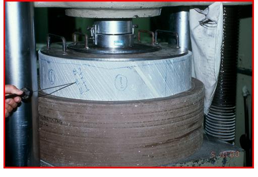
Figure 237. Photo. VTRC pushout test setup.
The tests at VT were performed by bonding the outside of the FRP shell to a slightly larger steel pipe section, supporting the steel pipe section, and pushing the concrete core so it begins to move out of the FRP shell. Tests were carried out at a displacement rate of 0.002 inches/min (0.0508 mm/min). The VT test setup for the pushout tests is shown in figure 238. The test results are summarized in table 54.
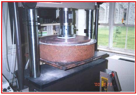
Figure 238. Photo. VT pushout test setup.
| VTRC (1) | VT (2) | Total | |
|---|---|---|---|
|
Number of tests |
13 |
6 |
19 |
|
Average peak bond strength (psi) |
29.95 |
14.1 |
24.9 |
|
Standard deviation (psi) |
9.75 |
20.1 |
15.3 |
Notes: (1) Load controlled test at 3,000 lb/min (1,362 kg/min). 1 psi = 6.89 kPa
(2) Displacement controlled tests. Bond strengths were corrected for voids in the bond area.
As shown in table 54, regardless of the test setup, the bond strength values obtained are fairly low, with an overall bond strength average of 170 kPa (24.9 psi). Test results also show a wide scatter of bond strength values. This wide variability of results could be related to factors such as the presence of voids between the concrete core and the interior of the FRP shell; possible damage to bond during cutting, shipping, and handling; temperature effects (expansion and contraction); and scale or size effects. Smaller bond strengths were obtained using the VT test setup compared to the VTRC test results. The bond strength magnitude differences are likely related to inherent differences in the test setup and load application procedure, as well as possible additional specimen disturbance of the VT specimens during the extra shipping and handling required to move the specimens from VTRC to VT.
A four-point creep bending test setup was designed and built to perform a creep test on an 18-ft (5.49-m) long section of 24-inch (0.61-m) diameter Lancaster composite pile. This pile was left over from VDOT's Route 40 Bridge project, where Lancaster composite piles were used for one bent. The test facility was built at VT's Kentland Farms, approximately 16 km (10 miles) west of Blacksburg, VA.
A photograph of the creep bending test setup is shown in figure 239. As shown in this photo, two dead weights of about 32 kN (7.2 kips) are hung at the middle thirds of the beam. These loads induce a maximum moment of about 58 kN-m (43 kip-ft). This moment is not a large percentage of the expected ultimate moment, but it is a moment that can be applied economically.
The centerline deflection curve obtained from the test is shown in figure 240.
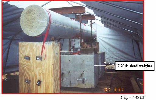
Figure 239. Photo. Creep bending test setup.
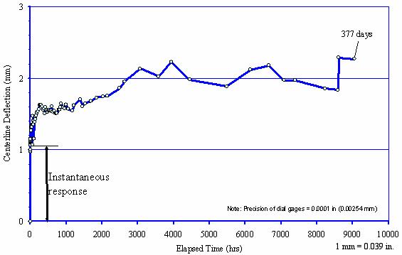
Figure 240. Graph. Creep deflection test
results.

