U.S. Department of Transportation
Federal Highway Administration
1200 New Jersey Avenue, SE
Washington, DC 20590
202-366-4000
Federal Highway Administration Research and Technology
Coordinating, Developing, and Delivering Highway Transportation Innovations
 |
| This report is an archived publication and may contain dated technical, contact, and link information |
|
Federal Highway Administration > Publications > Research > Structures > Covered Bridge Manual |
Publication Number: FHWA-HRT-04-098 |
Previous | Table of Contents | Next
To gain the most from the use of this manual, one begins with the basic definition of a covered bridge. For the purposes of this manual, a covered bridge is a timber structure supporting a deck surface that carries loads over an obstruction (e.g., a river). A covered bridge's structural components are protected from the elements by various coverings: walls, roofs, and decks. Figure 4 depicts a classic example of a covered bridge.
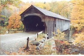
Figure 4. Typical covered bridge, Upper Falls Bridge, Weathersfield, VT.
The typical covered bridge uses heavy timber trusses to carry loads over an obstruction. The floor system spans between the longitudinal trusses, and distributes and carries the loads between those trusses. The bridge is completed by lateral bracing (elements that connect each truss, or side, of the bridge), a wall system, and roof intended to prevent weathering. The roof's primary function is to protect the structural timbers from the ravages of intermittent wetting. In bridge engineering terms, this style of structure is termed a through truss.
Some timber truss spans have deck surfaces exposed to the weather, with only the longitudinal trusses sheathed in by two walls and a very narrow roof-a style traditionally termed a pony truss or half-through truss. Figure 5 shows one of these especially rare remaining pony truss covered spans, the Comstock Bridge in Connecticut. The bridge is closed to vehicular traffic. As seen in the photograph, a covering a pony truss hides all details of the truss from view.
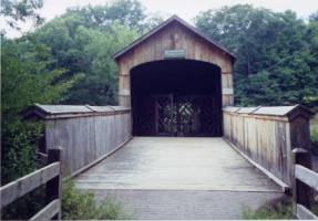
Figure 5. Pony truss covered bridge, Comstock Bridge, East Hampton, CT.
Many popular explanations have been offered for covering the bridge, but the simplest (and most common) reason was to preserve the supporting timbers. Timber bridges initially were built without coverings and failed in just a few years because of rot and deterioration, because chemical wood preservatives were not available or used. Builders familiar with the construction of houses, barns, and large community structures naturally added siding and roofs to help protect the bridge. They understood that the covering would soon pay for itself. They believed that regular maintenance and occasional replacement of the light covering was far easier and cheaper than building an entirely new bridge. North American covered bridges still serve after nearly 200 years, due in part to the continued soundness of the trusses, which was possible only with these protective coverings.
In addition to the floor, side-supporting trusses, roof, and siding, internal bracing is required to maintain the intended geometric shape and capacity of the structure. Bracing enables the structure to resist lateral load from wind and remain straight along its sides and square, thus enabling the structural components to support their greatest loads.
Covered bridges have been built in many different situations and in widely varied settings. However, the focus of this manual is on the most common surviving covered bridge-one intended to provide for vehicular loads, originally carriages, carts, and wagons, but now automobiles, trucks, and motorcycles.
There used to be many covered railroad bridges, but only a few still remain in the United States. According to the World Guide, there are only eight North American railroad covered bridges still standing. There may be others, but these are the ones observed in the guide.
Unfortunately, none of these bridges is still in regular service; all, have been abandoned or converted to other uses. The bridges at Clark's Trading Post in New Hampshire and the Fisher Bridge in Vermont serve an occasional tourist shortline. The very heavy loads of the railroads were sustained only through extraordinarily strengthened truss configurations. Lattice truss bridges were often doubled, using two vertical trusses instead of one. Other trusses (Howe trusses were popular for railroads) were strengthened by a variety of means. This provided the capacity for what remain the heaviest common design loads. Much of the material contained within this manual would apply to these few remote and unraveled spans.
The great majority of the original and surviving covered bridges crossed streams, usually with a single span. Many of the first crossings of the major Eastern rivers were accomplished with multiple span covered bridges. (The record, at 1,735 meters (m) ( (5,690 feet (ft))) long, was erected across the Susquehanna River between Columbia and Wrightsville, PA). However, the heavy traffic loads and wildly fluctuating water levels made for relatively short lifespans for those magnificent bridges. In addition, the close proximity of the covered bridge to water caused special problems related to accelerated deterioration due to rot, as well as the ever-present danger from floods.
Almost without exception, covered bridges were built to carry only a single, narrow lane. Most covered bridges were built at naturally narrow spots in the stream, and at right angles to the flow, to minimize the span length. This means that many covered bridges, which were built for much slower moving traffic than most modern automobiles, have at least modest curves at both ends of the bridge. These common existing bridge geometries-single lane and sharp curves at the ends-are both curses and blessings. The problem is that the geometry is often enough out of tolerance with modern traffic to make the covered bridge functionally obsolete; this is the main reason . More bridges have had to be replaced because of this than any other reason. On the positive side is the fact that these same geometries have contributed to the spans' longevity. The single-lane bridges limited the load carried on the structure at any one time. The sharp curves slowed traffic, thereby reducing the extra effect of the impact of bouncing vehicles. Slower speeds also reduced the number of accidents, which might have harmed the bridge. What was acceptable for horse-drawn vehicles, however, is sometimes not tolerable for cars and trucks.
Single-lane bridges are also far more likely to be well- proportioned than doublewides. A few 20th-twentieth century covered bridges have two-lane- wide, undivided roadways, rather than. They do not have the classic proportions that make many older covered bridges so photogenic and popular. The designers also had trouble spanning between the trusses, because the floor systems tend to be very heavy.
In a very few instances, the original builders needed to plan for two-way traffic to avoid the delays inherent in sharing use of the bridge. Today, according to the World Guide[1], only six remaining covered bridges provide this double-barrel capacity. These bridges have an added central, third truss. The center truss avoided extra long and substantially deeper floor beams, and separated opposing traffic flows. Furthermore, this central and more heavily loaded truss was often built deeper to take advantage of the pitch of the roof, thereby gaining additional strength and stiffness.
Another issue related to vehicle opening is the restricted vertical clearance. Most historic covered bridges have limited vertical clearance that prevents taller loads from passing through the bridge. This restriction has helped prevent some heavier vehicles from causing weight-related damage to the bridge. Unfortunately, it is common to find damage to the portals of covered bridges caused by attempted passage of overheight vehicles. This restricted vertical clearance contributes to the functional obsolescence of the bridge according to modern measures.
Figures 6 and 7 depict the technical terminology used with covered bridges. Many of the same terms used are common among covered bridges and other metal trusses, yet there are some terms that are unique to covered bridges. Further, some terms historically have been applied to covered bridge components in ways that are not necessarily compatible with similar components of metal trusses. Figure 6The following provides the terms as typically used in covered bridge work.
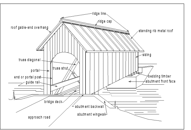
Figure 6. Bridge diagram-general terminology.
The longitudinal trusses are the backbone of the bridge. There are numerous configurations for these principal elements, and they are discussed in chapter 4. For the purposes of this overview, the primary trusses all contain three main components-a top chord, a bottom chord, and web members. A truss is a beam with a latticed web. As a beam has strength from its bending resistance, the structural capacity of any truss relies on the principal members resisting axial forces, -forces that act along the longitudinal axis of the component. These axial forces are either compression or tension.
Those members that run longitudinally along the top and bottom of the truss are termed chords. The upper, or top, chords are in compression. The bottom, or lower, chords are in tension. (This simplified characterization is intended for the most common single-span covered bridge. Those very few covered bridges that have continuous spans behave in a different way to reverse the forces in the chords, depending on location along the span, -a clarification that probably is not warranted for this purpose.) These chord members in a given truss can be of a single piece (say, the full length of the bride) or spliced. The chord members also may be built of multiple pieces, in cross section.
The vertical and diagonal truss members between the upper and lower chords that prevent those chords from moving relative to each other are called web members. These same members provide the transfer of vertical loads along the span to the supports at the ends. Some of these web members will usually be in compression; others will consistently be in tension.
Depending on the truss type, and their location within the truss, the diagonal web members may have special names, such as the end post, main diagonal, counter, or brace. The vertical elements are termed posts or verticals. The portion of the truss between verticals and diagonals is termed a panel. Figure 7 illustrates the truss components for a modified queenpost truss. Other configurations use similar terminology.
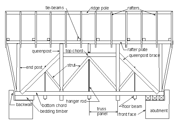
Figure 7. Diagram of queenpost truss-general terminology.
Most heavy timber trusses violate two basic modeling assumptions made in analyzing simple trusses. First, many chord and web members are continuous through some connections and not pinned at every truss joint. Second, many of the truss joints are detailed, with some eccentricities in member centerlines. Both of these variations from classic truss analysis theory mean that the truss members will also be resisting shear and bending forces, sometimes significant ones, particularly near the truss connections.
Covered bridge floor systems are configured in a number of ways but, in general, their heaviest members span between the trusses and are known as floor beams. There may be other members, supported on top of the floor beams that are aligned parallel to the bridge. These lighter members are termed stringers. The longitudinal stringers are sometimes referred to as joists, after their similarity to flexural members in building construction. In this manual, they will be referred to as stringers.
There is no clear separation between those bridges with stringers versus those without-virtually any type of truss configuration can support a floor beam and stringer system. Those with stringers have floor beams spaced farther apart-up to 3.0 to 3.7 m (10 to 12 ft). Figure 8 presents an example of a floor system with stringers supported by widely spaced floor beams. The floor beams in these types of bridges are, therefore, much heavier than those found in bridges with far more, but lighter, floor beams. An example of a floor system with closely spaced floor beams but without stringers is presented in figure 9.
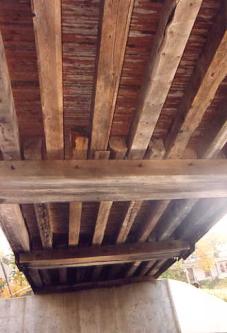
Figure 8. Floor system with stringers and floor beams-Warren Bridge, VT.
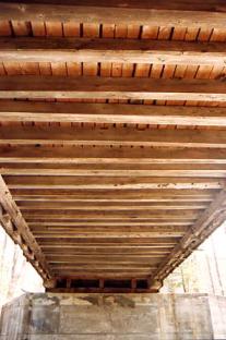
Figure 9. Floor system with floor beams, but without stringers-Hutchins Bridge, VT.
The uppermost structural layer, termed the decking, directly supports the vehicle wheels and transfers their load to the stringers or floor beams below. The decking rests on the stringer or floor beam. On occasion, there is more than one layer of deck planks;-as many as three is a common configuration.
If there are few, but heavy, floor beams, the stringers span between them and are spaced close enough to support the decking. These bridges have transverse (side-to-side) decking. In contrast, if there are many, lighter floor beams, the decking itself can span between the floor beams. These bridges, as a result, have longitudinal decking. In both cases, these bridges may have yet another layer of floor boards, running longitudinally, often termed running planks, or simply, runners. These are the actual wearing surface on which vehicles travel. These boards are like a wearing surface on a concrete deck, and sacrificial; i.e., they can be replaced when badly worn. Figure 10 shows an example of running planks. In this case, the top layer of deck planks run transversely (there are bottom planks spanning longitudinally between closely spaced floor beams).
Figure 10. Running planks-Hutchins Bridge, VT.
In a traditional covered bridge, the floor components, or decking, are all timber and may be in one or more layers. Many bridges have been repaired by using other materials, including steel stringers, concrete slabs, or even steel grating. There could be a layer of asphalt on top of the decking to provide some additional skid resistance, better traction, and increased durability.
Next in the discussion of bridge terminology is the lateral bracing system. These members help keep the structure both straight and square, and prevent twisting and torsion. The bracing installed in a horizontal plane at or immediately above the upper chord level is usually referred to as upper lateral bracing. Some people will refer to these elements as diagonal bracing. This description is ambiguous, however, because the web members of the main trusses include diagonals in the vertical plane of those trusses. The upper bracing includes members that span transverse to the axis of the bridge-these are termed tie beams (the preferred term used hereafter), or more properly struts (in structural engineering terminology, struts can support either compression or tension). The members that cross between the trusses, and that are connected to the ends of these tie beams, may be termed diagonals, cross bracing, or laterals. The preferred term is lateral braces. This system of tie beam and lateral bracing transfers the lateral wind loading on the upper half of the bridge along the span to the portal framing and then to the abutments. The lateral bracing system provides the resistance against wind loading and helps the top of the bridge to remain straight along its axis.
Figure 11 provides an example of an upper lateral bracing system. Looking closely, one can see this builder's use of a very unusual fish configuration of the laterals as they widen along the bridge and cross at both ends. The tie beams are supplemented with a center post that supports the ridge beam. The rafters are quite widely spaced with solid roof boards. The knee braces are short diagonal members mortised into the underside of the tie beams and the front face of the vertical posts.
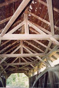
Figure 11. An unusual upper lateral system-Seguin Bridge, VT.
Some covered bridges also contain a lower lateral bracing system below the floor that is configured similarly to the top lateral bracing. It is called the bottom lateral system or lower lateral bracing. Bottom lateral bracing systems usually consist of diagonal members, connected to the ends of the floor beams. This system resists lateral movement of the bridge and helps to resist wind loading. Town lattice truss floors were often built with more closely spaced floor beams-so close, in fact, that a lower lateral system was not installed. However, for other configurations of trusses, a lower lateral system commonly was installed during the original construction. Subsequent floor replacements may have eliminated the lateral system, because unlike the upper level, where there is no other major component to replace it, the floor of the bridge can serve the same function. Even when the bottom lateral bracing is included, it shares lateral loads with the decking. Depending on how the decking is installed, its relative stiffness against lateral loads may mean it carries the majority of any lateral loading. If the bridge does not have bottom lateral bracing, a temporary bracing system should be installed during redecking operations. (Refer also to the related, more technical discussion of bracing in chapter 6 regarding the need to restore missing lower lateral bracing). An example of lower lateral bracing system is shown in figure 12. This nail-laminated deck is supported by transverse floor beams in a T Town lattice truss structure.
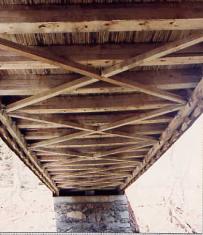
Figure 12. Lower lateral system-Williamsville, VT.
Finally, there are components that help to keep the bridge cross section square along its length. These short diagonal members are located in the upper corners of the bridge at regular spacing. In relation to their counterparts in metal trusses, they are termed knee braces (the preferred term and used hereafter). More colloquial terminology of covered bridges uses the term wind brace or sway brace (not to be confused with the overhead transverse frames in a metal truss). They usually connect the tie beam to the web members of the truss. These knee braces can also transfer lateral loads down, from the roof to the deck, if the deck level lateral system is much stiffer than the upper level lateral bracing system. In any event, these relatively small members can play very significant roles in holding the covered bridge in line. Of all structural members, They are also among the most vulnerable of the structural members to traffic damage. The covered bridge traffic aperture is constrained. When rehabilitating bridges for modern traffic, Many methods are used to provide this aperture bracing while maintaining maximum overhead clearance when rehabilitating bridges for modern traffic.
Figure 13 depicts very unusual knee braces made from the juncture of tree root and trunk, modeled after those used in old ships. In this case, the knees of the bridge are prone to being struck by larger vehicles, and these knees present less intrusion into the lane while still providing a strong connection between tie beam and truss vertical.
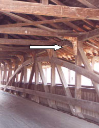
Figure 13. Unusual ship knee braces-Village or Great Eddy Bridge, in Waitsfield, VT.
Covered bridges also include a set of more ancillary components. The roof is comprised of rafters, just as in a house. The rafters are usually spaced closely enough that light sheathing boards can span longitudinally between them. The rafters may be connected at their midheight with horizontal rafter struts, whose function is to help stiffen the occasionally undersized rafters against sag. If these collars are under a lot of compression, their connections to the truss tops must be able to resist the added outward thrust. Those trusses, in turn, must be connected to each other well enough through the roof struts to resist the outward thrust at the roof eave level. There may be a longitudinal ridgepole or board at the peak, into which the rafters frame. Only very rare covered bridges had heavier structural longitudinal ridge beams in their roof systems. These heavy ridges had to be supported on roof struts that were stout enough to handle the bending from the weight of the ridge beam conveyed to the center of the strut via a vertical post (refer back to figure 11 for such an example).
Some bridges have an upright transverse frame that extends above the tie beam level and stiffens the roof system against distortion. This unusual lateral bracing system has been called various names, and there is no specific bridge-related terminology. It can be referred to as an upper wind frame (also shown in figure 11).
The bridge siding sometimes wraps around and continues on the inside of the trusses at the ends of the bridge, sometimes as far as 2.4 to 3 m (8 to 10 ft). This portal siding protects the end truss members from windborne rain and from the splash of water from entering vehicles. This siding is identified by various terms, including interior end siding, false door, or more commonly, shelter panel. The shelter panels can be of two types: -boarded over a short distance of the inside of the trusses, or as a separate structural extension beyond the ends of the trusses.
Figure 14 provides an example of a shelter panel that involves boards covering the end of the truss. Figure 15 shows an example of an end shelter panel separate from the truss. Figure 16 shows the overall framing of this end of the bridge before the completion of the siding and roof.
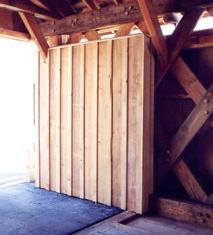
Figure 14. Shelter panel covering of truss ends-Fitch's Bridge, Delaware County, NY.
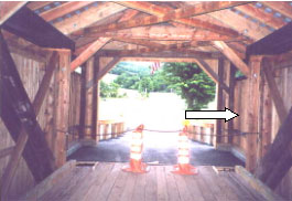
Figure 15. A shelter panel separate from the trusses-Hamden Bridge, Delaware County, NY.
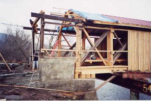
Figure 16. Framing of the independent shelter panel-Hamden Bridge, Delaware County, NY.
The ends of the bridge are called portals and include the siding above the entrances to the bridge (they are the entrance to any bridge with overhead bracing). Portals are areas that typically contain any distinctive decorations on the bridge; they may include some fancy finish work. On some bridges, various regulatory signs, such as height, width, or load restrictions, are placed on the portal.
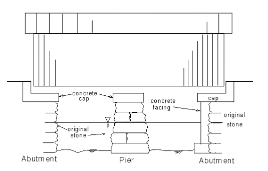
Following is a description of the bridge's foundations, those components that support the bridge-its foundations. The foundations at the end of the bridge are termed abutments. Any intermediate foundations are called piers. (Refer to figure 17 for terminology.) Most original multiple-span covered bridges were simple spans, framed separately but in line. Some Town lattices were originally continuous. Other covered bridges have intermediate piers (both permanent and long-term temporary) that were added to strengthen or to simply reinforce what had been a simple span. Some of these added piers are both well- intended and well- done. Others are just well- intended, albeit necessary. Most original foundations were constructed of stone, with or without mortar between the stones. More modern foundations, or in most cases, more recent rehabilitations, may have included reinforced concrete, cast either in front of the stone or in place of the original stone. The comparison of the economy and durability between concrete and stone is debatable; however, stone is often cited as much more aesthetically pleasing.
There are usually a number of small timber components between the foundation material and the underside of the main truss components. These timbers are labeled by a number of different terms, including bedding timbers, bearing timbers, or bearing blocks. These shorter timbers, placed at right angles beneath the chords, are intended to be sacrificial and readily replaced, if and when they rot and deteriorate, thereby preventing deterioration in the main truss components. In some bridges, these timbers are longer (placed parallel to, and below, the bottom chord) and extend out beyond the face of the foundation, where they support the main truss members. These longer timbers are often termed bolster beams, because they help support the bridge by effectively shortening the clear span. Figure 18 shows an example of bolster beams-the large timbers positioned directly beneath the bottom chords and above the concrete cap, jutting out beyond the front face of the cap. The two longitudinal timbers below the floor beams and between the bolster beams are distribution beams.
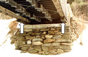
Figure 18. Bolster beams-Worrall's Bridge, Rockingham, VT.
Covered bridges have been around long enough and have been built in so many forms that they have accumulated a trove of oddities.
The National Society for the Preservation of Covered Bridges has, since 1956, periodically published the World Guide, beginning with the first edition in 1956.[1] The most recent edition was printed in 1989, and the next edition is being prepared. Although not error- free, the World Guide provides the only available comprehensive documentation of the world's covered bridges. The information contained in this section of this manual is intended for general interest regardless of any errors contained here. It is not intended to end arguments, nor start new ones. It is intended to help the reader gain perspective about covered bridges in the United States.
There are 880 covered bridges listed in the World Guide[1] that are located in the United States. About 810 of them (according to J. Conwill, major contributor to the 1989 edition) could be described as authentic, according to this manual's definition. Given the loss of covered bridges to arson, flood, and neglect, this number is decreasing. However, new and authentic covered bridges are being built occasionally, so the total number is a moving target. In effect, then, there are nearly 900 covered bridges in the United States. Analysis of the covered bridge population database reveals the following.
There is much controversy about the age of older covered bridges. In this regard, the World Guide is considered quite misleading, with many unsubstantiated dates. According to Conwill, there are three with authenticated dates before 1830.
Whatever their precise construction dates, these are old bridges-much older than any made of steel or concrete. Only stone arches predate covered bridges in the United States.
It is also interesting to examine the geographic distribution of the contenders for the oldest remaining covered bridge title. As one would expect, the oldest bridges were built in the Middle Atlantic and New England States. One might expect to be able to track the migration of covered bridges across the States, with the West Coast being the last region to build covered bridges. It is very possible, if not probable, to use the available information for the remaining bridges to draw misleading conclusions about this potential spread of technology. However, covered bridges were built in California long before they appeared in many of the intervening States (as early as 1862). This may well reflect the leapfrog of population that followed the California Gold Rush, as well as the availability of large timbers in the West.
Another classification of the covered bridge distribution involved the decade of original construction. Of the 880 surviving bridges, 195 were built between 1870 and 1879, and 149 more were built between 1880 and 1889. Covered bridge building continued to decline steadily, to a low of seven surviving examples that were built between 1940 and 1949, and only five from 1950 to 1959. More than a dozen were built in each decade of the 1960s, 1970s, and 1980s, which shows a recent resurgence in their popularity.
To understand this category, a brief discussion of measuring a bridge's length, or span, is necessary. Many conventional bridges have a fairly well-defined support point, with distinct bearing between the foundation and the superstructure of the bridge. The distance between the centers of these bearing points establishes the bridge's span or length-an important feature related to the design and/or determination of the capacity of the bridge. However, conventional bridges also tend to incorporate very limited structure outside these clearly defined bearing points. A single-span steel girder bridge, for example, with 30.5 m (100 ft) between the centers of the end bearing points, might be built with girders that are only 31.1 m (102 ft) long.
Even if the end of the bridge is difficult to clearly identify, there is usually a joint in the roadway surface to allow expansion and contraction with thermal effects. Therefore, when measuring the span of a conventional bridge, one can determine both its span length and total length without much controversy.
Covered bridges, in contrast, do not usually contain a single and clear bearing point between foundation and superstructure. Instead, there may be a number of timbers that help transfer the load from the bridge trusses to the foundations. This transfer occurs over a distance that could be several feet at each foundation. Furthermore, the portal framing can extend fairly far out onto the abutments, in the interest of increased protection to the vulnerable and heavily loaded end timbers. These end conditions often have made it difficult to clearly establish the span length for many covered bridges. A dimension that is sometimes substituted is the distance between abutments.
These end conditions can create big differences between the face-to-face of abutment dimension and the readily perceived overall length of the bridge's apparent superstructure. To further complicate the situation, some span measurements have included the length of the roof overhang at the portals in the length of the bridge, while others do not.
The Bridgeport Bridge in Bridgeport, CA, built in 1862, has the longest recorded structure length, at 71.0 m (233 ft). The second longest bridge is the Blenheim Bridge in Schoharie, NY, built in 1855, at 69.5 m (228 ft). However, the Blenheim Bridge has the longest distance between abutments at 64.0 m (210 ft) (see figure 19). A classic historic covered bridge, the Blenheim Bridge is supported by long trusses supplemented with arches. It is one of the very few surviving double-barrel bridges. Many authentic covered bridges were built with clear spans greater than 30.5 m (100 ft).
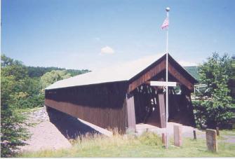
Figure 19. Blenheim Bridge-longest clear span in the United States.
Many people associate covered bridges only with New England and
a very few other States. Interestingly, there is at least one
covered bridge still standing in 30 States. Pennsylvania has, by
far, the most, with 227 surviving examples. This is followed by
Ohio, with 143; Vermont, with 100; and Indiana, with 93. Those
States with only one surviving, authentic covered bridge are:
Minnesota, Mississippi (this bridge's authenticity has been
questioned), New Jersey, and South Carolina.
Table 1. Locations and dates of covered bridges by State*
|
State |
Number |
Ranking |
Earliest |
Latest |
|---|---|---|---|---|
|
Alabama |
14 |
c1850 |
1934 |
|
|
California |
13 |
1862 |
1984 |
|
|
Connecticut |
5 |
1841 |
1976 |
|
|
Delaware |
2 |
c1870 |
1870 |
|
|
Georgia |
17 |
c1840 |
1975 |
|
|
Illinois |
9 |
1854 |
1987 |
|
|
Indiana |
93 |
4th |
1838 |
1922 |
|
Iowa |
12 |
1869 |
1969 |
|
|
Kentucky |
13 |
c1835 |
c1925 |
|
|
Maine |
12 |
1857 |
1990 |
|
|
Maryland |
6 |
c1850 |
1880 |
|
|
Massachusetts |
17 |
1832 |
1985 |
|
|
Michigan |
6 |
1832 |
1980 |
|
|
Minnesota |
1 |
1869 |
||
|
Mississippi |
1 |
1966 |
||
|
Missouri |
5 |
1868 |
1980 |
|
|
New Hampshire |
57 |
5th |
1827 |
1987 |
|
New Jersey |
1 |
1866 |
||
|
New York |
29 |
7th |
1823 |
1982 |
|
North Carolina |
5 |
c1860 |
c1910 |
|
|
Ohio |
143 |
2nd |
1829 |
1986 |
|
Oregon |
51 |
6th |
1914 |
1989 |
|
Pennsylvania |
227 |
1st |
180_ |
1988 |
|
South Carolina |
1 |
1909 |
||
|
Tennessee |
6 |
1876 |
1977 |
|
|
Vermont |
100 |
3rd |
c1820 |
1982 |
|
Virginia |
9 |
c1800 |
1920 |
|
|
Washington |
6 |
1905 |
1976 |
|
|
West Virginia |
17 |
1852 |
1911 |
|
|
Wisconsin |
2 |
1876 |
1962 |
|
| 30 States | 880 |
*From the World Guide to Covered Bridges[1], published by the National Society for the Preservation of Covered Bridges, 1989 edition. The caveat about dates cited in the table is explained more thoroughly in a previous section of this chapter, "Oldest Covered Bridge in the United States."
According to information provided in the World Guide, the 880 surviving covered bridges are supported by 18 distinct truss configurations, and multiple variations thereof. (Chapter 4 contains a description of each of the truss configurations.) The Burr arch is by far the most popular, with 224 surviving examples. The Howe truss is used in 143 bridges, followed by 135 Town lattice bridges, 101 queenpost truss bridges, and 95 multiple kingpost truss bridges.
Table 2. Truss configurations-numbers and lengths*
|
Truss Configuration |
Number |
Title |
Single Span Length ("L") Without Variations |
||||
|---|---|---|---|---|---|---|---|
|
Shortest |
Longest |
Ranking |
|||||
|
feet |
meters |
feet |
meters |
||||
|
Brown |
2 |
100 |
30.5 |
116 |
35.4 |
||
|
Burr |
224 |
and variations |
32 |
9.8 |
222 |
67.7 |
1st in L |
|
Childs |
7 |
50 |
15.2 |
104 |
31.7 |
||
|
Haupt |
2 |
and variations |
85 |
25.9 |
134 |
40.8 |
|
|
Howe |
143 |
20 |
6.1 |
200 |
61.0 |
2nd in L |
|
|
Inverted bowstring |
2 |
75 |
22.9 |
100 |
30.5 |
||
|
King |
30 |
22 |
6.7 |
70 |
21.3 |
||
|
Long |
27 |
51 |
15.5 |
170 |
51.8 |
5th in L |
|
|
Multiple king |
95 |
and variations |
36 |
11.0 |
124 |
37.8 |
|
|
Paddleford |
10 |
35 |
10.7 |
120 |
36.6 |
||
|
Paddleford arch |
11 |
78 |
23.8 |
183 |
55.8 |
3rd in L |
|
|
Partridge |
6 |
64 |
19.5 |
154 |
46.9 |
||
|
Post |
1 |
165 |
50.3 |
0.0 |
6th in L |
||
|
Pratt |
8 |
and variations |
36 |
11.0 |
96 |
29.3 |
|
|
Queen |
101 |
and variations |
25 |
7.6 |
130 |
39.6 |
|
|
Smith |
20 |
59 |
18.0 |
172 |
52.4 |
4th in L |
|
|
Tied arch |
4 |
37 |
11.3 |
136 |
41.5 |
||
|
Town |
135 |
25 |
7.6 |
162 |
49.4 |
7th in L |
|
|
Town and supplemental |
14 |
80 |
24.4 |
129 |
39.3 |
||
|
Warren |
6 |
and variations |
30 |
9.1 |
87 |
26.5 |
|
|
Double multiple |
4 |
and variations |
63 |
19.2 |
111 |
33.8 |
|
|
Double town |
4 |
98 |
29.9 |
122 |
37.2 |
||
|
Double warren |
1 |
116 |
35.4 |
0.0 |
|||
|
Other / unknown |
23 |
||||||
|
880 |
|||||||
*From the World Guide to Covered Bridges, published by the National Society for the Preservation of Covered Bridges, Inc., 1989 edition.
Reasons for Using Covered Bridges vs. Other Alternatives
As stated earlier, the reason these timber structures were covered was simply to help protect the timber from the ravages associated with periodic wetting. Those involved with early truss structures have stated that timber truss structures without coverings would often fail after 10-20 years of service. Coverings quickly proved their worth by greatly extending the life of the structure-so much so that the use of timber structures without coverings was only for a brief period of time.
The development of the timber truss allowed these bridges to span greater distances than those with beam-only structures. They were also able to surpass the spanning capability of arch structures, whether of stone, masonry, or timber.
The development of processes that produced wrought iron and cast iron in larger capacities during the mid-1800s soon led to truss types made of progressively more metal. Timber trusses quickly lost their popularity in the late-1800s and were used less and less after the early 1900s, except in those areas of plentiful large timber.

