U.S. Department of Transportation
Federal Highway Administration
1200 New Jersey Avenue, SE
Washington, DC 20590
202-366-4000
Federal Highway Administration Research and Technology
Coordinating, Developing, and Delivering Highway Transportation Innovations
 |
| This report is an archived publication and may contain dated technical, contact, and link information |
|
Federal Highway Administration > Publications > Research > Structures > Covered Bridge Manual |
Publication Number: FHWA-HRT-04-098 |
Previous | Table of Contents | Next
Engineers working on historic covered bridges must face many issues when assessing the capacity and condition of existing wood members. This chapter addresses some of the technical design issues related to calculating capacities of existing members and structures, as well as those for new component replacement members.
Determining the appropriate material properties and allowable stresses to use in evaluating an extant covered bridge is challenging. The current NDS specifications contain allowable stresses that are based on extensive information and experience with timber, yet there are still concerns that the NDS values are quite conservative when applied to the timber found in historic covered bridges.
The first step in determining member capacities involves identifying the wood species. As mentioned in "Wood Typical to Historic Covered Bridges" in chapter 10, several species of wood may exist within an extant covered bridge, so it is important to determine the wood species for the particular structural members under consideration. It is appropriate and relatively inexpensive to obtain small samples of the members and have them identified by a wood scientist (for clarification, see "Wood Species Identification in chapter 15).
The next step in assessing a member's capacity involves determining the grade that most accurately describes the members. This identification is more problematic than identifying the species. Again, it is appropriate to seek assistance from an expert. There are several popular timber grading associations, many of which offer services involving onsite and in situ timber grading. The cost for this service is relatively nominal, compared to the entire analysis cost, and is an important aspect of evaluating the bridge. However, the grader can only provide visual grading for the material that is visible. In addition, the grader cannot definitively identify the grade of a structural component if portions of the member are hidden from view. The grader can determine, however, what the member is not, based on the member faces that are visible (e.g., the member does not meet the criteria of a select structural member, or does not meet the requirements for a number 1 grade).
Therefore, engineers still must exercise some judgment. For example, if a given member does not meet a select structural grade, it probably is safe to consider it as meeting the next lower grade. It is important to understand that grading rules are a function of the species and grading association that promulgates the rules covering those species. What is a select structural in one species and its associated rules may not be the same in another species. Further, some species and grading associations do not have provisions for all grades for all species and in all timber size categories.
After identifying the species of the member(s) in question and their corresponding grading, the next step involves selecting an appropriate allowable stress. Begin with the NDS; however, the NDS allowable stresses are based on extensive tests of newer wood samples and use a fairly complex mathematical process to extrapolate raw laboratory tests of small clear specimens to allowable stresses in full-size members. One of the major components in deriving allowable stresses from laboratory tests is based on a probabilistic approach using a 95 percent exclusion rule. In simple terms, the allowable stress is based on a failure strength that 95 members out of 100 will exceed. In other words, statistically only 5 members out of 100 will possess a failure stress less than that used for determining the tabulated allowable stress. This particular aspect of timber design has no counterpart in other common structural materials, such as steel or concrete, because of the variability of wood both among species and within the same species.
Some designers reasonably argue that, although this approach helps design new timber structures, it may be too conservative for evaluating an historic timber structure such as a covered bridge. Bridge components that have served successfully for at least 50 years (and maybe much longer) have been tested by time. Those components that contained the weaknesses implied by a 95 percent exclusion rule have either already failed or have not (yet) been highly stressed. Therefore, it may be appropriate to consider some other exclusion limitation-some have suggested 80 percent. However, the current specifications do not address this issue, and it has not attracted much attention because it affects very few structures.
For more information on this topic, refer to guidance provided within the American Society for Testing and Materials (ASTM) Specifications:
At this writing, research continues to examine the issue of what allowable stresses to use in existing timber. However, the authors of this report have not identified any definitive published work to assist users of this manual in relation to this issue. This discussion is intended to encourage reflection regarding assumptions about evaluating historic covered bridges. Until other information is available, the allowable stresses published by NDS should be used as the basis for the analytical evaluation of historic covered bridge capacities.
Figure 99 presents an interesting materials issue. The original truss diagonals in this figure were made from American Chestnut. Modern specifications do not provide allowable stresses for this species, because it is so rare. Therefore, the allowable stresses must be determined using ASTM procedures.
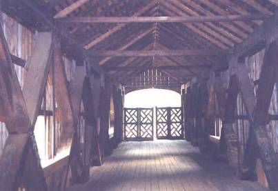
Figure 99. American Chestnut (allowable stresses are not in the NDS)-Comstock Bridge, East Hampton, CT.
Although this topic has been in the literature for awhile, it has not received much notice, and it has significant applications in timber-covered bridge capacities. The following is a brief synopsis of the issues involved in this very complex topic.
Until the 1960s, common practice was to establish the allowable tensile stress in wood members as a theoretical extrapolation of its measured failure stress in the tension zone of bending specimens. In part, this was due to the difficulties of developing tensile load testing equipment that could test timber specimens to failure without simply breaking at the grips. The grip zone failure casts legitimate doubts on the tensile stresses in the member at failure. Eventually, new grips were developed that led to satisfactory results in axial tension to failure tests. Unfortunately, the newer tests demonstrated that wood has less tensile strength than previously predicted by the flexural tests.
For smaller specimens, the differences between axially-induced and bending-induced tensile stresses were not major. However, as specimen size increased, the differences became significant. The 1977 NDS specifications introduced a new reduction factor of as much as 40 percent for allowable tensile stresses for members 254 mm (10 inches) and wider, and number 1 grade or less. This new reduction had a major effect on the allowable capacity calculations for timber trusses with larger chord and web members.
Many buildings offer practical examples that illustrate the rationale behind this change in the specifications. Many World War II vintage timber warehouses were built with heavy timber trusses and have demonstrated significant and frequent tensile fractures in the bottom (tension) chords. Figure 100 depicts one such example, albeit in a timber that had substandard slope of grain and a knot defect at a critical joint area. Figure 101 shows a classic example of a tensile failure in the bottom chord of a covered bridge.
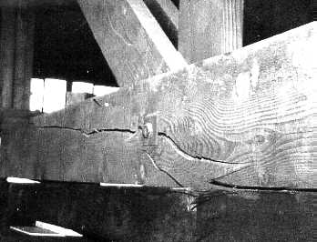
Figure 100. Example of tensile failure of a bottom chord element in a World War II timber building.
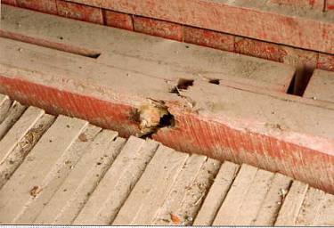
Figure 101. Example of a tensile failure of a bottom chord in a covered bridge.
Because evaluating timber-covered bridge load capacities can lead to considering changes in specifications and the effects of such changes, it is good to keep this issue in mind. It also reinforces the importance of paying particular attention to the tensile members in covered bridge trusses.
The historical development of allowable shear stresses in timber elements includes much controversy. This manual does not contain a lengthy discussion of this topic, but the relevance of horizontal shear is particularly important in evaluating existing floor beams and/or designing replacement components.
In short, the predicted shear capacity of a floor beam often is substantially less than loads routinely crossing it. For many years, the NDS specifications have allowed an increase in the basic horizontal shear allowable stresses for those members with limited or no-end checks or splits (double if no defects). The allowable shear stresses have decreased significantly, primarily because of the growth of kiln-dried lumber. Kiln drying tends to induce checking at the ends of the pieces. Because this coincides with the location of maximum shear stresses in most simple-span applications, the code-promulgating bodies have been decreasing this allowable stress conservatively. It has not made much difference in typical lumber scale structures, where shear stresses are not commonly the limiting condition. However, it has had quite an impact on heavy timbers; this led to the NDS provision permitting increased allowable shear stresses with minimum checking at ends. There is no guarantee that checking will not occur with new lumber, but it is relatively easy to establish in existing beams. Even with this increase, shear still often controls the capacity of the floor beam.
Those involved in covered bridges are still trying to determine why floor beams appear to have more available strength than current specifications recognize. Unfortunately, there is no consensus concerning how to change the current specifications to increase shear allowable stresses.
An example of horizontal shear failure (albeit in a vertical plane in this post) is shown in figure 102, above the diagonal notched into the post. Note that the right side is offset upward (with respect to the left side) above the diagonal.
Horizontal shear stress is most likely to become an engineering issue when designing or analyzing the floor members in timber bridges. One of the quirkier aspects of calculating shear stresses in floor members relates to the AASHTO provisions about load position with respect to the support. The commonly accepted methodology is that point loads are included in calculating actual shear stress only if these loads are located farther from the theoretical center of the beam support than the beam depth. However, live loads (in this case, vehicular wheel loads) are included only if they are no closer than "3 times d" (d being the depth of the beam) away from the support (see AASHTO specifications, section 13.6.5, "Shear Parallel to Grain").[2] For a typical bridge floor beam (250 mm (12 inches) deep), in which the span may be 4.6 to 5.5 m (15 to 18 ft), these provisions can substantially change the design stress calculation, due to the relatively small aspect ratio of beam span-to-depth.
Because the dead load of the floor system is usually insignificant compared to the effect of vehicular loading, it is reasonable to neglect dead loading. This means that the analyst would evaluate the shear stresses with the load placed at 3d from the center of floor beam support. A conservative analysis that checks the stress with the load located only a single beam depth away may indicate that a given floor beam is overstressed in shear, while a more refined analysis might well demonstrate that the beam is acceptable.
Because of the apparent increasingly conservative assessment of shear capacity built into the current allowable shear stresses, one should be wary of being additionally conservative with the loading conditions. Therefore, using the current specifications, vehicular live loading shear conditions should be checked at 3d away from the support.

