U.S. Department of Transportation
Federal Highway Administration
1200 New Jersey Avenue, SE
Washington, DC 20590
202-366-4000
Federal Highway Administration Research and Technology
Coordinating, Developing, and Delivering Highway Transportation Innovations
 |
| This report is an archived publication and may contain dated technical, contact, and link information |
|
Federal Highway Administration > Publications > Research > Structures > Covered Bridge Manual |
Publication Number: FHWA-HRT-04-098 |
Previous | Table of Contents | Next
Repairing and/or strengthening an existing historic covered bridge often can be more challenging than designing a new one. The reasons include:
When repairing historic masonry, one problem is finding replacement mortar as soft as the original. Hard replacement mortar will do more harm than good by overstressing the stones when it expands. An analogous problem occurs when repairing heavy timber trusses. Replacing existing members with new, stiffer ones can change the structure's behavior under load by redistributing the stresses. Even identical replacement members can behave differently than the members they replace, depending on how they are fit and how the span is supported while the repairs are being made. The structural consequences of these load path shifts can be serious.
The following sections of this chapter present a variety of methods that have been used to repair and strengthen covered bridges. Many measures have been in use for a long time; others are relatively new. It is important to recognize that increasing attention to meeting the requirements of the Secretary of Interior's standards for historic preservation prevent some of these measures from being pursued now (see Chapter 18 for a more thorough discussion and reference citation). Some actions may have been popular at different times and in specific areas (due to the preference of certain builders and engineers), but were poor choices for a variety of reasons, as discussed here. A summary of practices to follow and things to avoid is presented at the end of this chapter.
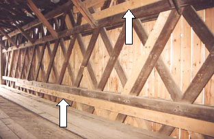
The most basic way to repair a covered bridge is to replace deteriorated components in-kind. This entails using timbers of similar size and connection detail as the replaced members. At times, simply substituting a stronger wood species may provide additional strength and service life. The deteriorated component may either be completely replaced or partially replaced. Figure 148 provides an example of replacement of a deteriorated truss element (the first, light-colored vertical post). The next two posts have been repaired by adding new bottom elements adjacent to existing elements that were broken at the bottom.
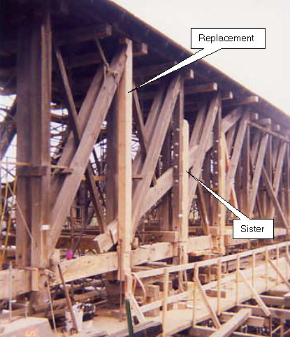
One important issue related to member repairs (or replacement) is identifying appropriate means for relieving the forces in the replaced element before its removal. The structure may have to be completely shored on false work to allow removing the component, or temporary bracing may be used to loosen it. A member should not be removed while it is under load. It is virtually impossible to install the replacement element with that original loading in it, which means that the load distribution in the repaired structure will be different.
If a partial replacement is installed, the connections of the new component must be appropriate. There may be limited space for the new midlength connections. Although it is possible to design, detail, and install a proper repair for a given weakness or problem, repairs often are not well done and do more harm than good. Good repairs require precise work in each step, in accordance with the following guidelines:
Design: The repair must have adequate design capacity for the given loading and must maintain the intended function of the component, while matching the desired fixity of the connections. The required shoring and repairing sequence may be the designer's responsibility.
Detailing: The repair must be detailed so that the work is feasible under field conditions. It must also match the original design. The reasoning behind the detailing and design must be understood by those performing the repair in the field.
Installation: The workmanship must be careful and precise for the repaired member or connection to perform as intended. The workmanship in cutting must be high-quality. Shoring and installation must follow design intents. Interaction between the designer and the repair contractor must be constant and convenient, and adjustments must be made for any problems discovered as the work progresses.
The last section of this chapter references three case studies presented in the appendices that discuss specific bridge rehabilitation projects. Each article provides examples of various means of repairs and strengthening (strengthening is discussed in more depth in the following section). There are a number of other specific ways to repair truss elements, as discussed below.
Town lattice trusses often contain web elements that have become split at their bottoms. The split may be the result of high stress with a corresponding horizontal shear split from the trunnel forces. The split may be the result of ice impact. In addition, the elements may contain an area of rot from poor weather protection; this is most commonly discovered between the mating surfaces of a lattice member against the adjacent elements during reconstruction projects. When the deterioration of the element is extensive enough to be addressed, there are two viable actions: the entire element may be removed and replaced in-kind, or a supplemental element may be installed immediately adjacent to the damaged element. In the jargon of Town lattice trusses, the elements are termed sisters. The sister is rarely full-length; it is often only about half the original's height.
Figure 149 provides an example of a sistered repair of damaged Town lattice elements. The shorter ones are sisters.
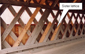
Figure 149. Sister elements in Town lattice-Silk Road Bridge, Bennington, VT. Photo
Figure 150 depicts an example of repair of a damaged end post with a sistered element. In this case, the sister element is connected with timber shear blocks and some bolts. The original diagonal was cut short to allow it to bear on the new sister element along the original line of the diagonal, thus keeping the axial action unchanged. Figure 151 provides an example of a partial replacement of a damaged element. The original element is half-lapped to the new and outside splice timbers that help hold the splice tight. Square shear keys project out from the center of the lap splice.
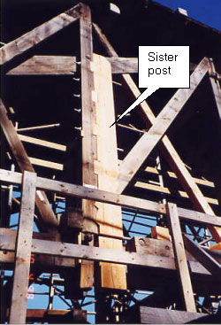
Figure 150. Sistered post repair in Long truss-Downsville Bridge, Delaware County, NY, during its major rehabilitation in 1999. Photo
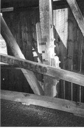
Figure 151. Partial post replacement in multiple kingpost truss-Union Village Bridge, VT. Photo
One common way to strengthen a covered bridge involves reinforcing existing timber components with new ones. The new members must be connected to the existing structure to allow both the new and existing components to share the loading. An example would be installing extra chord members on an existing Town lattice truss. This would best be done with the entire structure supported on false work to relieve the load in the trusses before adding the new material. Replacing the existing pegs with longer ones would be necessary to accommodate the additional outside chord elements. The holes in the new outside chord elements would have to be drilled using the existing holes as a pattern. This requires placing the new material on one side at a time, followed by drilling holes from the opposite side of the chord.
Related to this, extra chord elements can be added to an existing Town lattice truss, as shown in Figure 152. This relatively long single span was modified by adding a pier. The extra chord elements were intended to strengthen the truss over the pier with its new condition of negative moment.
Another way to strengthen a covered bridge involves installing supplemental steel rods, cables, or rolled shapes to an existing member. An example would be adding post-tensioning to an overstressed lower chord members or tension splice. Figure 153 presents an example of metal elements added to an existing bottom chord. In this case, the truss is actually a tied arch. A pair of high-strength, post-tensioning rods installed below and parallel to the bottom chord can be seen on close inspection. The designer should carefully consider the differential thermal characteristics between metal and wood.
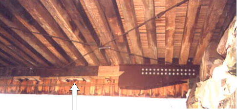
Figure 153. Meta elements added to an existing bottom chord-Lincoln Bridge, Woodstock, VT. Photo
A classic way to strengthen the original trusses in covered bridges has been to install a timber arch (or arches) adjacent to the original truss. Theodore Burr's system, patented in the early 1800s, incorporates just such an arch with a truss. The Burr arch combination was very popular and continues to support more covered bridges than any other configuration, as mentioned in chapter 2. Since then, for structural reasons, arches have been retrofitted to virtually every timber truss type. Figure 154 depicts an example of an arch element added to a Town lattice structure. The deformations in the arch demonstrate that it was unable to support all the loads that were transferred to it. The bridge is now closed to vehicular traffic.
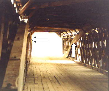
Figure 154. An arch element added to a Town lattice structure-Scott Bridge, Townshend, VT. Photo
Analytically establishing the degree of load sharing between the juxtaposed truss and arch has always been challenging. There seems never to have been any consensus on the load-bearing intent behind Burr's original structural form combination. Some analysts have asserted that the trusses are meant to carry the dead load, while the arches are meant to carry the live load. Others disagree, saying that the arch is potentially stiff enough to carry virtually all loads, and the truss simply distributes point loadings into the more arch-friendly distributed configuration. The many variables that cause further confusion between theoretical and actual behaviors include:
Yielding at arch and truss supports.
Fabrication tolerances in the arch and truss connections.
Local buckling in the arch.
Relative stiffness in the connections between arch and truss.
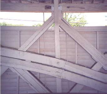
An example of such deliberations is depicted in figure 155. A single bolt connects these single-piece arch segments to the truss post. Such connections are commonly distorted, indicating a connection that is inadequate to carry the loads imposed on it. The addition of an arch to an existing truss must address the real forces imposed on the connection.
Interestingly, the arch often is not actually large enough to support a significant portion of any applied loads. In other cases, however, the arch supports most of both the live and dead loads. Analysts and designers should be cautious and conservative in evaluating load paths and sharing in any such hybrid structure, whether designing a new one or retrofitting and repairing an existing one.
Due in part to the complexities encountered when reinforcing original covered bridges to carry current loads, the entire original floor system commonly is replaced with an independent, load-carrying structure. This new enclosed bridge could be longitudinal steel beams with a concrete or timber floor, which act independently (or even, in some extreme examples, also support the original trusses) from the covered bridge. While some argue that this approach retains, rather than destroys, the original covered bridge, others note that the resulting bridge has been completely gutted. An objective concern regarding this rather drastic repair method is that future safety inspections of the structure (mandated by Federal law) will necessarily focus on the new floor (which is supporting the vehicle loads), while the existing and original trusses and roof structure may be ignored. Without even the basic, minimum maintenance repairs, the original wooden shell may deteriorate rapidly, even though it is carrying only minor loading.
Frequently, engineers familiar with steel trusses attempt to repair timber trusses using details similar to the ones they know from their past work. Classic examples of this unfortunate transference to covered bridges include:
Often, these repairs are a poor substitute for compatible repairs installed by skilled craftsmen. In many instances, these repairs can even further weaken the structure. The ill-advised repair may well reduce the net section in critical tension members, thereby further reducing capacity.
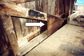
Figure 156. Steel plates at heel connection of queenpost truss-Power House Bridge, Johnson, VT, before its collapse in 2001.
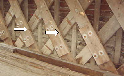
Figure 157. Spliced lattice tail replacements-River Road Bridge, Troy, VT.
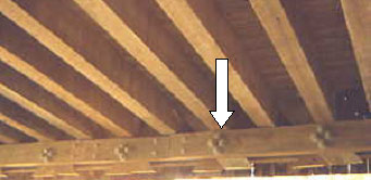
Figure 158. Use of steel bolts in chord replacement-Kingsley Bridge, Shrewsbury, VT.
There are many research, marketing, and trial efforts aimed at using fiber-reinforced polymers (FRP) to reinforce steel and concrete elements. While there is some discussion in research literature concerning their use in timber buildings work, they are not commonly used in covered bridge work. Advances in using these new materials with timber elements may make them important tools for covered bridge work in the future.
FHWA is sponsoring a research program to develop FRP/glulam composites and the related design and material specifications for bridges. Research is also underway to explore strengthening historic covered bridges to carry modern traffic. At the time of this manual's publication, that work was not completed.
Although rare in covered bridges, there are instances of floor beams that have been modified by adding a steel assembly to effectively post-tension the floor beam or convert it to an inverted kingpost truss. Figure 159 shows such an installation. A metal assembly was attached to the underside of a timber floor beam to add capacity. In this example, the beam action of the floor beam has been converted to an inverted queenpost truss.
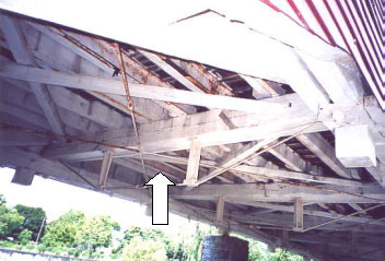
Figure 159. Installation of metalwork beneath a timber floor beam-Wehr Bridge, Lehigh County, PA.
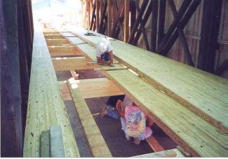
Another method of strengthening an existing floor system is to replace the decking with glue-laminated panels. Usually, this would also include replacing the existing floor beams with glue-laminated elements. The glue-laminated elements provide higher strength than sawn elements and thereby provide much higher strength with less or no change in the depth of the elements. Figure 160 shows a strengthening of an existing floor system by using glue-laminated deck panels and floor beams. In this instance, the deck panels were fabricated full-length to avoid transverse joints along the floor.
It is very difficult to state with certainty that some actions are acceptable and others are not. The following summarizes how to repair and strengthen historic covered bridges. Many of these "Practices to Follow" and "Practices to Avoid" involve topics other than specific treatment of bridge deficiencies, but are related to successful repair and rehabilitation projects.
Practices to Follow:
Initiate direct communication with the various entities that will be involved with the project and work together to find a solution to the needs, without assuming that approval will be granted after the fact. Stakeholders include owners, state historic preservation offices, local historic societies, the public at large, and elected officials. These people should be kept informed of the progress of the project, through its various phases, until it is complete.
Guide selection of design vehicle to the lowest weight possible to minimize the potential need for element replacement.
Pursue traditional covered bridge practices, including appropriate timber joinery, with appropriate engineering and drawings to guide repair and/or strengthening work.
Restrict work on historic covered bridges to engineers and contractors with proper credentials and experience on similar timber structures.
Consider carefully the benefits of design/build projects to allow the engineer and contractor to work as a team for the benefit of the project. Compared with projects for more conventional bridges, the relatively limited number of engineers and contractors experienced with this type of work leads to greater confidence in the outcome of the project if mutual strengths can be joined in a true team spirit.
Retain the design engineer to observe construction, especially related to superstructure repairs. Some owners rely on the contractor to perform the work with limited or no oversight by the design engineer, or with oversight by persons without experience with timber construction and practices, thereby risking the success of the project.
Consider how the structure will be supported or moved during the rehabilitation or strengthening to ensure that it is practical, achievable, and safe.
Practices to Avoid:
Do not attempt to support heavier vehicular loads than necessary for the particular bridge and site.
Do not close a bridge to vehicular traffic without considering the increased risk of vandalism or arson due to reduced interruption of traffic.
Do not assume that the original structure is too weak, or unable to be repaired or strengthened for the desired capacity.
Remember that if the original floor and independent floor support are removed to save the trusses, then continued attention to maintenance and repair of the trusses is mandatory to prevent their unintended demise.
Be very careful about adding steel components directly adjacent to timber (thereby promoting condensation-caused rot that cannot be observed or inspected).
Do not add arch elements to a truss without carefully evaluating all forces and stresses created at the connections and arch ends.
Do not use steel connectors in lieu of timber pegs without carefully considering the consequences of the change in relative stiffness of the connected elements.
Often the best way to depict specifics about covered bridge repair or strengthening is to discuss a particular project. Appendices B, C, and D contain articles that were prepared about recent rehabilitation projects that dealt with three distinct truss types

