U.S. Department of Transportation
Federal Highway Administration
1200 New Jersey Avenue, SE
Washington, DC 20590
202-366-4000
Federal Highway Administration Research and Technology
Coordinating, Developing, and Delivering Highway Transportation Innovations
 |
| This report is an archived publication and may contain dated technical, contact, and link information |
|
Federal Highway Administration > Publications > Research > Structures > Covered Bridge Manual |
Publication Number: FHWA-HRT-04-098 |
Previous | Table of Contents | Next
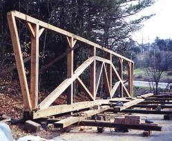
Figure 251. Opening day parade.
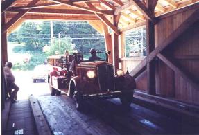
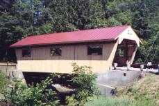
Figure 252. Completed replacement truss.
The Power House Covered Bridge was constructed in 1870 over the Gihon River in Johnson, VT, to connect School Street with what is now Route 100C (see figure 253). The structure was supported by queenpost trusses with a total length of about 22.2 m (73 ft). Unfortunately, the trusses have experienced significant distress for many years, and the bridge was rebuilt on numerous occasions. In 1995, further work was performed to remove the timber floor from the trusses and install an independent floor system of timber deck on steel beams supported directly on the abutments.
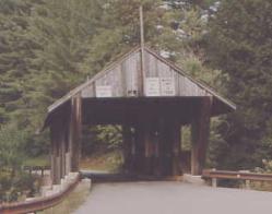
Figure 253. Bridge before collapse.
On March 8, 2001, the covered bridge shell collapsed under the weight of heavy snow (see figure 254). The failure of the roof structure pushed the tops of the trusses outward, and they rotated until they ended up in the stream. The existing deck structure remained intact and undamaged.
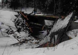
Figure 254. Bridge after collapse from snow.
The community decided to rebuild a replica of the shell of the bridge, but wanted to keep the independent floor system. Therefore, the new shell did not have to be designed to support vehicular loading, but did have to support snow loading. The collapse demonstrates that snow loading can be significant.
Design and construction activities took place during 2002.
Before collapse, the bridge contained a bottom chord of three sticks, an unusual arrangement and difficult to join to the single plane of verticals and diagonals. It is unknown if this was the original arrangement or installed during one of the repairs. There are several other queenpost truss covered bridges in the vicinity. A review of the details of those bridges indicated that two chord sticks were common; this accommodates an easier connection to the diagonals and verticals. Therefore, the pair concept was adopted for the replica (refer to figure 255). The photograph shows the conventional tabled joints to the posts and a scarf joint in the near bottom chord element.
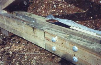
Figure 255. Double bottom chord arrangement with scarf joint.
The lack of significant overhead bracing was a major cause for the collapse. Accordingly, a stronger system was installed, similar to that used in the Mill Bridge, described in appendix H.
Wind loading bows the bottom of the sides of the bridge, because there is no deck to serve as a diaphragm. Therefore, a connection between the sides of the covered bridge and the existing timber deck/steel beam
superstructure was deemed appropriate. The deflection of the floor system under vehicular loading is accommodated in the connection to the timber shell. Horizontal restraint is therefore required, in combination with vertical freedom (see figure 256).
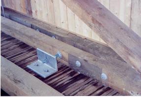
Figure 256. Connection between deck and bottom chord.
The trusses had to be designed for their own weight and the weight of snow. Although the trusses do not support vehicular loading, the effect of snow loading was substantial, and the truss components were selected to match the previous sizes as closely as possible. Because the shell structure does not receive vibrations from passing vehicles, it was decided that metal roofing would be used to minimize the potential for heavy snow drifting on the bridge.
The heel connection of queenpost trusses is a critical feature. The other queenpost bridges in the vicinity of this bridge provide a number of different arrangements for the connection. Figure 257 presents details of the connection selected for this installation. The diagonal at the top left is notched into the top of the bottom chords. The post is tabled into the chord. The smaller element on the end is a support for the siding, and is not a part of the truss.
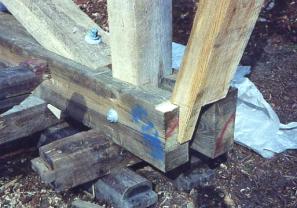
Figure 257. Heel connection details.
A queenpost truss feature that provides a slightly different challenge is the support of the rafters. In this bridge, a rafter plate is situated above the top chord and extends the full length of the bridge. The tie beams are connected to the tops of the posts, but unlike most situations, were located in the same plane of the rafter plate. This requires an unusual three-way connection (see figure 258).
Figure 258. Connection of tie beam, truss vertical, and rafter plate.