U.S. Department of Transportation
Federal Highway Administration
1200 New Jersey Avenue, SE
Washington, DC 20590
202-366-4000
Federal Highway Administration Research and Technology
Coordinating, Developing, and Delivering Highway Transportation Innovations
 |
| This report is an archived publication and may contain dated technical, contact, and link information |
|
Publication Number: FHWA-HRT-06-078
Date: June 2006 |
|||||||||||||||||
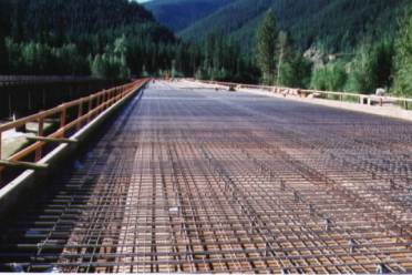
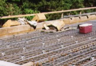
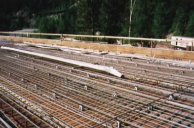
Job Site Evaluation of Corrosion Resistant AlloysAPPENDIX E FHWA Project Number MT-01-01TEA-21 INNOVATIVE BRIDGE CONSTRUCTION PROGRAM Evaluation Report State: Montana. State DOT Contact: Mr. Nigel Mends [(406) 444-9221]. NBI Bridge Number: P00001180+0.399-1. Project Type: Replacement. Location: Bridge crossing the Middle Fork of the Flathead River on U.S. 2 near Essex, Flathead County, MT. Innovative Material: Solid Stainless Steel Type [American Iron and Steel Institute] AISI 316LN or 2205 reinforcement and related hardware. Bridge Description: The new bridge is replacing an older one that is structurally obsolete. It is 190 m long with four spans of lengths 43, 52, 52, and 43 m. The two-lane roadway width is 12 m. Alignment is tangent across the bridge except for the last span which lies on a 5-degree spiral. Four welded plate weathering steel girders, each with a 900x22 mm web and 400 mm wide flange which varies in thickness from 19 mm at midspan to 64 mm over the piers, support the deck. The cast-in-place deck has a constant 2 percent superelevation. The specified deck thickness is 215 mm and the concrete cover over the top reinforcement 60 mm. Innovation Justification: One end of the bridge terminates on land owned by Glacier National Park and the other on land administered by Flathead National Forest. The Flathead River that the bridge crosses is under jurisdiction of the United States Fish and Wildlife Service. Permitting was complicated because these, as well as the U.S. Army Corps of Engineers and various State agencies, were involved. Consequently, it was reasoned by the Montana Department of Transportation (MDT) that any future repairs, rehabilitations, or replacement would be complex and difficult. The bridge was anticipated to require relatively high maintenance if it were built using conventional reinforcement (ECR) because it is in a heavy snow area that experiences wintertime applications of MgCl2 (liquid form) and numerous freeze-thaw cycles. In addition, because of the rural setting and mountainous surroundings, any bridge closure involves a 480-km (300-mile) detour. For this reason, extra expense that promoted longevity with minimal maintenance was considered justified. Construction Sequence: The four piers were formed and poured during the second half of 2001, and the deck was placed in June and July 2002. The site was visited on June 24, 2002, at which time approximately two-thirds of the reinforcement had been placed. Figure 35 shows a photograph of the deck at that time.
Figure 35. View of deck with stainless steel reinforcement placement in progress. Reinforcement Specification: The reinforcement for both mats was specified as pickled AISI Stainless Steel Type 316LN or 2205 which was to be delivered to the construction site free of any rusting. Concrete Specification: The concrete was termed, “Special Deck,” with properties as specified in table 10.
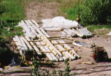
Job Contractor: Frontier West, Inc. P.O. Box 16295 Missoula, MT 59808 Steel Supplier: Empire Steel. The reinforcing steel was acquired from Spain and shipped to the United States. Cutting and bending, where necessary, were performed in Colorado; and the steel was then shipped to the job site. Guard angles were provided by Watson Bowman Acme Corp. in New York. Material Cost: The reinforcement cost was estimated as $3.50/kg ($1.60/lb). Five bids were obtained that ranged from $4.10/kg ($1.86/lb) to $5.27/kg ($2.39/lb). The lowest bidder for the overall project was awarded the contract, with the reinforcement cost being $5.20/kg ($2.36/lb). A total of 106.5 tons of reinforcement was required. Job Site Storage: Two truckloads arrived at the job site on June 13, 2002, and the remaining three truck loads during the week of June 17. These were off-loaded onto wooden 2-ft by 4-ft supports on the ground. Figure 36 shows a photograph of this storage. The storage time was short, as placement commenced shortly after delivery. Packaging and covering are described below. No problems were encountered in connection with delivery and storage.
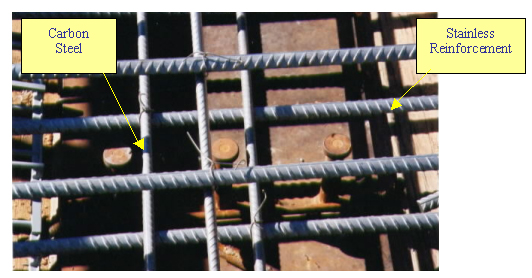
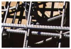
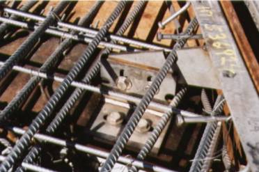
Figure 36. Photograph of bundled/wrapped bars at the job site. Presence of Carbon Steel: Shear studs on the top girder flanges are carbon steel. Figure 37 shows how these penetrate the bottom mat of stainless steel. The specification requires that there be no contact between the studs and reinforcement. This was accomplished using plastic caps over the studs. These had not been placed at the time on this site visit, and so they do not appear in figure 37. Stainless steel in the structure backwalls is tied to black bar.
Problems: The following difficulties were encountered when incorporating stainless steel into this project.
(a)
(b)
Figure 39. View showing cardboard packaged bent reinforcement details.
Figure 40. View of a guard angle adjacent to an expansion joint.
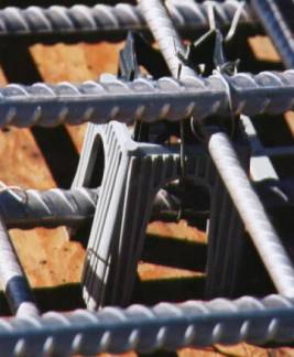
Figure 41. Array of plastic chairs to which bars from both mats are tied.
Figure 42. Closeup view of a plastic chair to which bars are tied.
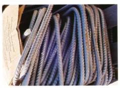
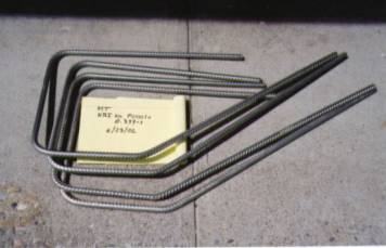
Material Acquisition: Four bent bar details were made available from the job site for testing by FAU and FDOT. Figure 43 shows examples of these.
Figure 43. Examples of stainless steel reinforcement details acquired from the job site
|
|||||||||||||||||