U.S. Department of Transportation
Federal Highway Administration
1200 New Jersey Avenue, SE
Washington, DC 20590
202-366-4000
Federal Highway Administration Research and Technology
Coordinating, Developing, and Delivering Highway Transportation Innovations
 |
| This report is an archived publication and may contain dated technical, contact, and link information |
|
Publication Number: FHWA-HRT-06-115
Date: August 2006 |
||||||||||||||||||||||||||||||||||||||||||||||||||||||||||||||||||||||||||||||||||
Index, Structural Behavior of Ultra-High Performance Concrete Prestressed I-GirdersCHAPTER 2. BACKGROUND AND PREVIOUS RESEARCH2.1 UHPC Constituent MaterialsThe UHPC used in this study is a patented product of a major worldwide concrete manufacturer. The product is a reactive powder concrete that is marketed under the name Ductal. This product has a number of different material compositions depending on the particular application. A typical composition is provided in table 1. The constituent material proportions were determined, in part, based on an optimization of the granular mixture. This method allows for a finely graded and highly homogeneous concrete matrix. Fine sand, generally between 150 and 600 micrometers (μm), is dimensionally the largest granular material. The next largest particle is cement with an average diameter of approximately 15 μm. Of similar size is the crushed quartz with an average diameter of 10 μm. The smallest particle, the silica fume, has a diameter small enough to fill the interstitial voids between the cement and the crushed quartz particles. Dimensionally, the largest constituent in the mix is the steel fibers. In this study, the fibers in the mix had a diameter of 0.2 millimeter (mm) (0.008 inch) and a length of 12.7 mm (0.5 inch). Given the relative sizes of the sand and the fibers, the steel fibers are able to reinforce the concrete matrix on the micro level. A further discussion of the properties of the steel fibers is provided in section 2.3.
2.2 Steam-Treated UHPC Material PropertiesAn associated research program was conducted in parallel with the research program discussed throughout this report.(2) This associated research program was launched to determine the material characteristics of the UHPC studied in this report. A brief summary of the results for steam-treated UHPC is presented in table 2.
1 MPa = 145 psi 2.3 Steel Fiber Material PropertiesThe steel fibers used in this test program were straight steel wire fibers manufactured by Bekaert Corporation. The fibers have a nominal diameter of 0.2 mm (0.008 inch) and a nominal length of 12.7 mm (0.5 inch). The chemical composition of the fibers is shown in table 3. Note that a thin brass coating is applied to the fibers during the drawing process; therefore, virgin fibers may be gold colored. This coating disappears during the mixing process and is no longer clearly visible during the casting of the UHPC.
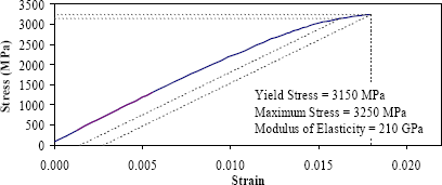
The intended function of these fibers within UHPC requires that the fibers have a very high tensile strength. The manufacturer's specified minimum tensile strength is 2,600 MPa (377 ksi), and tension tests are performed as a means of quality control on the fiber production. The results from three of these tests are presented in figure 1. The average yield strength of these fibers as calculated by the 0.2-percent offset method is 3,156 MPa (457.7 ksi). The modulus of elasticity is 205.4 gigapascals (GPa) (29790 ksi) and the ultimate strength is 3,268 MPa (474.0 ksi).
1 MPa = 145 psi Figure 1. Graph. Sample tensile stress-strain response for steel fiber reinforcement. 2.4 Relevant Background Research2.4.1 Prestressing Strand Development Length by Steinberg and LubbersResearchers at Ohio University recently completed a study of the force transfer behavior of prestressing strand in UHPC.(10) This research program focused on determining the development length of 12.7-mm, 1,860-MPa (0.5-inch, 270-ksi) low-relaxation prestressing strands in UHPC, similar to that studied in the present research program. Predefined lengths of strands were cast into blocks of UHPC, then the strands were pulled until slip or strand rupture occurred. Embedment lengths of 305, 457, and 610 mm (12, 18, and 24 inches) were investigated. In all tests, fracture of the strand occurred before significant slip of the strand could occur. These results indicate that the development length of this type of strand in UHPC is less than 305 mm (12 inches). 2.4.2 Shear Capacity of AASHTO Type II Girders by TawfiqIn the early 1990s the Florida Department of Transportation sponsored a research program focused on determining the shear capacity of high-strength concrete bridge girders. This research, performed by Tawfiq, experimentally determined the shear capacity of AASHTO Type II girders composed of 55-, 69-, and 83-MPa (8-, 10-, and 12-ksi) concrete.(11,12) The AASHTO Type II girder cross section tested included 16 strands in the bottom flange, 2 in the top flange, and a 0.2-m by 1.07-m (8-inches by 42-inches) composite deck cast onto the top of the girder. Six tests were completed, with two at each compressive strength level. The loading arrangement for the test included offset three-point loading with a shear span-to-depth ratio of approximately 2.5. The shear reinforcement in these girders was designed according the AASHTO Standard Specifications for Highway Bridges.(13) Two #4 stirrups were spaced every 152 mm (6 inches) for the first 0.92 m (4 ft) from the bearing, then two #4 stirrups for every 203 mm (8 inches) for the next 0.92 m (4 ft). The remainder of the span had single #4 stirrups at 203- and 305-mm (8- and 12-inch) spacings. The overall shear capacity of these girders is the primary result from these tests that is applicable to the UHPC girder tests performed as part of the current research program. On average, the shear capacity exhibited in each of the six tests was approximately 1,200 kilonewtons (kN) (270 kilopounds (kips). The shear capacity was not significantly influenced by the compressive strength of the concrete. 2.4.3 Shear Capacity of Small UHPC Beams by Hegger, et al.Researchers at the Institute of Structural Concrete at RWTH Aachen University have recently completed several tests investigating the shear capacity of UHPC beams. This research focused on determining the shear capacity of a 305-mm-deep (12-inch-deep) prestressed concrete beams containing no mild steel shear reinforcement.(14) The UHPC used in this research program was similar to the UHPC discussed throughout this report, although it did contain a slightly larger percentage of steel fiber reinforcement (2.5 percent). The cross section of the I-beams tested in this research program contained eight 7-wire, 15.2-mm (0.6-inch) prestressing strands in the bottom flange. The bottom flange of the beam was 292 mm (11.5 inches) wide and the top flange was 221 mm (8.7 inches) wide. The web of the beam was 150 mm (5.9 inches) tall and 71 mm (2.8 inches) thick. The overall beam length was 3.5 m (11.5 ft) and each beam was loaded in four-point bending. The average ultimate shear capacity of these UHPC beams was 273 kN (61.4 kips). Given the size of these beams, this result is very similar to the shear capacities that were observed in the full-scale AASHTO Type II shear tests that are presented in chapters 5 and 6. The analytical procedure presented in section 6.5.3 indicates that the average tensile stress carried by the UHPC across the shear failure plane was approximately 14 MPa (2 ksi). 2.4.4 Flexural Capacity of High-Strength Concrete Girders by Russell and BurnsRussell and Burns investigated the behavior of prestressed concrete girders composed of high-strength concrete.(15) In particular, this study focused on the static and fatigue behaviors of composite bridge girders under flexure and shear loadings. The girder flexural test completed in this research is of most interest to the present study. This research was completed on Texas Type C girders, which are of similar shape but slightly shallower than AASHTO Type III girders. The tested girder was 1.02 m (40 inches) deep, with a 203 mm (8 inches) deep composite deck cast on top. The deck was 1.82 m (72 inches) wide and composed of 42-MPa (6-ksi) concrete. The girder was composed of 69-MPa (10-ksi) concrete and spanned 14.6 m (48 ft). The flexural test girder contained twenty-eight 12.7-mm, 1,860-MPa (0.5inch, 270-ksi) low-relaxation prestressing strands, each stressed to 138 kN (31 kips). Twelve of the strands were draped. The flexural testing of this girder included both static and fatigue loadings. Initially, sufficient load was applied to crack the girder in flexure and shear. Flexural loading was then repeated for 225,000 cycles, after which the girder was loaded to flexural failure. The flexural capacity of this 1.02-m-deep (48-inches-deep) composite girder was 43.3 kilonewton-meters (kN-m) (38,300 kip-inches) of applied load. Russell and Burns note that "[t]he girder failed in pure flexure with yielding of the strands and large plastic rotations. Cracking extended into the deck slab."(15) The load-deflection response of the girder indicates that the midspan deflection at failure was approximately 180 mm (7 inches).
|