U.S. Department of Transportation
Federal Highway Administration
1200 New Jersey Avenue, SE
Washington, DC 20590
202-366-4000
Federal Highway Administration Research and Technology
Coordinating, Developing, and Delivering Highway Transportation Innovations
 |
| This report is an archived publication and may contain dated technical, contact, and link information |
|
Publication Number: FHWA-HRT-07-021
Date: April 2007 |
|||||||||||||
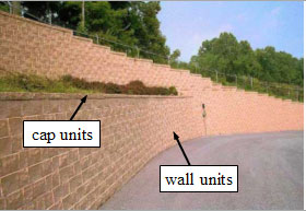
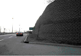
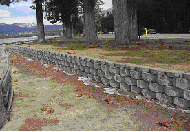
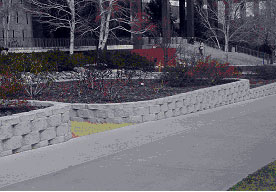
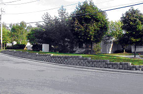
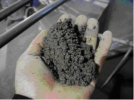
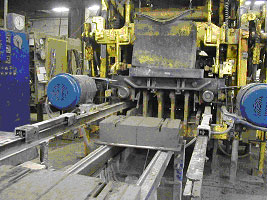
Durability of Segmental Retaining Wall Blocks: Final ReportCHAPTER 1: INTRODUCTION AND SCOPE1.1 OVERVIEWSegmental retaining wall (SRW) systems are commonly and successfully used in a range of applications, including highway projects. Their popularity can be attributed to a combination of reduced construction costs, versatility, aesthetic appearance, ease of installation, and an increasing number of proprietary designs available in the market. Despite these inherent advantages, there have been some reported problems with durability of SRW blocks in cold climates. The deterioration of some SRW installations in State highway agency (SHA) applications has resulted in concern over the long-term performance of SRW systems and has led to stricter specifications and, in some cases, restrictions on future use of SRW systems. In response to these concerns, an FHWA-funded research project was initiated to determine the cause and extent of SRW block distress, to identify and recommend test methods for improving durability of SRW systems, and to recommend specifications for SHAs to ensure long-term durability and performance of SRW systems in highway applications. This report summarizes the key findings of this project and provides guidance on producing durable SRW blocks to ensure long-term performance of SRW systems in highway applications. The remainder of this chapter provides a brief overview of SRW systems, highlights some of the key technical aspects associated with SRW blocks, and describes broadly the scope of the SRW block deterioration problem at the time that this research project was launched. Lastly, this chapter provides a brief summary of the organization of the remaining chapters in this report. 1.2 SRW SYSTEMSSRW systems have become increasingly popular in the past decade for earth retention and landscaping applications. These systems, consisting of dry-stacked (mortarless) concrete masonry units, can be used either as conventional gravity structures or as part of a reinforced soil system in conjunction with horizontal layers of soil reinforcement (figures 1, 2, and 3). Wall heights can range anywhere from 200 mm (millimeters) (8 inches) to 6 (meters) m (20 feet (ft)) depending on the specific application as shown in figure 4. SRW units are manufactured in concrete block plants at typically dry consistencies using low water contents and/or low overall paste contents to achieve a stiff consistency for compaction into molds and to allow almost immediate demolding (figures 5 and 6).
Figure 4. Photos. Example applications of SRW systems.
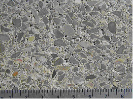
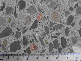
Due to the low paste contents of SRW units, a material characterized by a network of irregularly shaped voids is produced, as depicted in figure 7, in which the internal structures of ordinary and SRW concretes are contrasted. These voids are termed "compaction voids" since they are formed during the compaction process, and their role in the durability of SRW units is still not fully understood (Pigeon and Pleau, 1995). From the data obtained under this FSRW project, the volume fraction of compaction voids can account for up to 25 percent of the total volume of concrete. As comparison, the air void content of air-entrained concretes is approximately in the range of 4-8 percent by volume (Kosmatka and Panarese, 1994).
Figure 7. Photos. Comparison of internal structures between SRW and ordinary concretes. Presently, in the United States, the material performance of SRW units is evaluated based on the following standards (NCMA, 2002):
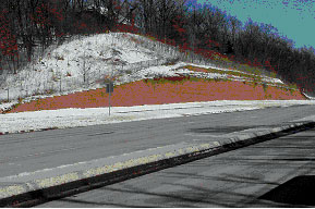
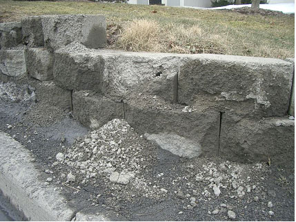
ASTM C 1372 specifies dimensional tolerances, compressive strength, absorption, and density of the material, as well as freeze-thaw durability. ASTM C 140 is actually a masonry standard covering test procedures for dimension measurement, compressive strength, absorption, and density, while ASTM C 1262 covers procedures for freeze-thaw durability testing of SRW units. 1.3 RESEARCH BACKGROUND AND SCOPEAlthough SRW manufacturing technology has improved in recent years and durable units can be produced, there have been reported cases of deterioration of SRW units in the field. This is particularly the case in cold regions where frost exposure in combination with deicing salts can severely damage the units (Thomas, 2003). An example of a damaged SRW is shown in figure 8.
In May 2000 a survey of SRW performance was released to selected cold weather States and responses were obtained from Illinois, Iowa, Kansas, Michigan, Minnesota, Missouri, New York, Wisconsin, and Wyoming. All States have minimum strength and maximum absorption regulations, and Iowa, , Michigan, Minnesota, New York, and Wisconsin all require freeze/thaw testing according to ASTM C 1262 (ASTM 2003) (described in detail throughout this report). Illinois requires 100 cycles conducted according to ASTM C 666 "Standard Test Method for Resistance of Concrete to Rapid Freezing and Thawing" (2004) a requirement that producers have had difficulty meeting due to the severity of the test. Illinois, Kansas, Minnesota, Missouri, Wisconsin, and Wyoming all have regulated wall sizes and/or design requirements based on durability concerns with SRWs. Minnesota and Wisconsin have set the most rigorous requirements based on the severity of the problem and the volume of walls that have been constructed. In recent years, both Minnesota and Wisconsin Departments of Transportation (Mn/DOT and WisDOT respectively) have conducted extensive field surveys to assess the level of damage to in service SRWs. In July of 2001 a report was released by Mn/DOT detailing the condition of 104 SRWs (Embacher et al., 2001). Only walls built before 1994 were examined, with an emphasis on walls located at the same intersection facing different directions and constructed during the same year. Privately owned walls identified by industry representatives were also investigated. Each wall was assigned a distress rating between 0 and 5, with 0 indicating the worst distress, and 5 indicating no visible distress. Only 7 percent of the walls examined were classified as poor to very poor, but it was found that over 50 percent of the walls exhibited freeze-thaw damage. Walls located at parking lots or close to the roadway exhibited the most damage, due to increased amounts of snow accumulation and water runoff, therefore allowing for greater saturation, and exposure to deicing salts. Walls exposed to fertilizer also exhibited more damage, due to phosphates in the fertilizers behaving in a manner similar to that of deicing salts. In the summer of 2000 WisDOT randomly surveyed 87 walls throughout the State. Walls were between 1 and 15 years old with the majority of walls being between 5 and 10 years old. A database was created with photographs of each wall and specific rating and wall details for each wall. Walls were rated based on the distress manual developed in the Mn/DOT wall survey. A total of 18 walls (roughly 20 percent of those surveyed) displayed freeze-thaw distress, with 8 showing low severity, 6 showing medium severity, and 4 showing high severity. It was concluded that even though a lower percentage of Wisconsin walls displayed damage than in Minnesota, freeze-thaw durability is still a major issue and should be examined in more detail. The distress shown by existing walls has resulted in more rigorous requirements for the construction of walls in many States as can be seen in figure 6. Minnesota and Wisconsin have been the most aggressive in setting guidelines for freeze-thaw requirements of SRWs. After March 1, 2001, Mn/DOT required all walls to conform to a strict list of requirements (Mn/DOT, 2001), as follows. No walls are allowed in locations where they will be directly supporting roadways or bridge abutments. Walls greater than 1.2 m (4 ft.) in height have no restriction on location on roadways with traffic volumes less than 5,000 annual average daily traffic (AADT), for roadways with traffic volume between 5,000 and 20,000 AADT, the wall must be greater than 6.0 m (20 ft.) beyond the outside shoulder or gutter line, and for roadways with traffic volume greater than 20,000 AADT, the walls must be located greater than 9.1 m (30 ft.) beyond the outside shoulder or gutter line. The maximum allowed wall height is 3.0 m (10 ft.), and it is assumed an additional 0.6 m (2 ft.) will be buried below ground. All blocks being placed in Minnesota must conform to ASTM C 1372 (2003), and have a minimum compressive strength of 38 megapascals (MPa) (5,500 pounds per square inch (psi)) for any individual unit, and 40 MPa (5,800 psi) for an average of three units. Walls must also exhibit a weight loss for each of 5 specimens at the conclusion of 90 cycles of not less than 1 percent, or 4 out of 5 specimens at the conclusion of 100 cycles of not less than 1.5 percent when subject to ASTM C 1262 (2003) testing in 3 percent saline solution. The specifications are the same for cap units except they need only be subject to 40 and 50 cycles as opposed to 90 and 100 cycles. One sample of every 5,000 units of continuous production should be tested in accordance to ASTM C 140 (2000) with the exception that coupons must be tested, and tests on full size units are not allowed. WisDOT allows only six block manufacturers to create the facing of SRWs (WisDOT, 2000). Blocks shall exhibit a minimum compressive strength of 34 MPa (5,000 psi) and a maximum of 6 percent absorption when subject to ASTM C 140 (2000) testing. Walls must also exhibit a weight loss for each of 5 specimens at the conclusion of 40 cycles of not less than 1 percent, or 4 out of 5 specimens at the conclusion of 50 cycles of not less than 1.5 percent, when subject to ASTM C 1262 (2003) testing in 3 percent saline solution. All tests shall be conducted by a WisDOT approved independent testing laboratory for each lot of 5,000 blocks. Some measures are also being taken by State departments of transportation (DOTs) to reduce further damage to inservice walls that have already shown freeze/thaw distress as shown in Figure 9. The most common technique being used is the application of silane or siloxane coatings. The purpose of these coatings is to try to keep moisture from penetrating the surface of SRWs and therefore, reduce future damage. The long-term effects of sealers are still unknown, and in lab settings, these types of coatings have shown mixed results. Sealers have proved to be useful in reducing deicer salt scaling on insufficiently air-entrained conventional concrete, but the protection is limited over time (Hazrati, 1993). On surfaces with adequate salt-scaling resistance, Hazrati (1993) observed that sealers actually increase the amount of salt scaling damage. In response to the concerns raised above regarding frost resistance of SRW blocks, a pooled fund project was initiated in 2003 by the Federal Highway Administration, under which The University of Texas at Austin (UT), Cornell University and Texas A&M University engaged in a research project on SRW durability. The objectives of this research were to determine the mechanisms responsible for the deterioration of SRW units in the field, identify variables that contribute to the durability of these units, and provide recommendations for the production of durable units and for the protection of existing SRWs.
1.4 ORGANIZATION OF REPORTThe remainder of this report presents the key findings from FHWA Project No. DTFH61-02-R-00078. This final project report draws from several documents generated under this project, including:
The remainder of this report is organized into the following chapters: Chapter 2 contains a brief literature review on freeze-thaw damage, with a primary emphasis on SRW block durability. Chapter 3 summarizes field evaluations of SRW systems conducted under this project, with emphasis on SRWs used in highway applications in Minnesota and Wisconsin. Chapter 4 describes a comprehensive laboratory research program focusing on frost resistance of SRW blocks. The work includes detailed studies on sampling issues, freeze-thaw test methods, impact of salts on damage, and efforts to develop a more realistic approach to test full SRW blocks under simulated exposure conditions. The main focus of the chapter is on refining and improving ASTM C 1262 to make it more reliable, reproducible, and user friendly. Chapter 5 summarizes the key findings of this research project and provides guidance on how to specify and test SRW blocks to ensure long-term durability. Appendixes A and B contains newly proposed versions of ASTM C 1262 (freeze-thaw testing of SRW blocks) and ASTM C 1372 (standard specifications for SRW blocks), based on the key findings from this research project. These appendixes are intended to serve as stand-alone products that can readily be considered for adoption by SHAs and the American Association of State Highway and Transportation Officials (AASHTO).
|