U.S. Department of Transportation
Federal Highway Administration
1200 New Jersey Avenue, SE
Washington, DC 20590
202-366-4000
Federal Highway Administration Research and Technology
Coordinating, Developing, and Delivering Highway Transportation Innovations
 |
| This techbrief is an archived publication and may contain dated technical, contact, and link information |
|
Publication Number: FHWA-HRT-11-022
Date: November 2010 |
Field-Cast UHPC Connections for Modular Bridge Deck Elements
View PDF (488 KB) PDF files can be viewed with the Acrobat® Reader® FHWA Contact: Ben Graybeal, HRDI-40, 202-493-3122, benjamin.graybeal@dot.gov
This document is a technical summary of the unpublished Federal Highway Administration (FHWA) report Behavior of Field-Cast Ultra-High Performance Concrete Bridge Deck Connections Under Cyclic and Static Structural Loading, which is available through the National Technical Information Service (NTIS), www.ntis.gov. NTIS Accession No. of the report covered in this TechBrief: PB2011-101995
OBJECTIVEThis TechBrief highlights the results of a study aimed at evaluating the performance of field–cast ultra–high performance concrete (UHPC) connections linking precast concrete bridge deck components.
INTRODUCTIONThe use of modular bridge deck components has the potential to produce higher quality, more durable bridge decks. However, the required connections often prove lacking, resulting in less than desirable overall system performance. Advanced cementitious composite materials, whose mechanical and durability properties far exceed those of conventional concretes, present an opportunity to significantly enhance the performance of field–cast connections, thus facilitating the wider use of modular bridge deck systems. UHPC represents a class of such advanced cementitious composite materials. Of particular interest here, UHPCs can significantly shorten the development length of embedded discrete steel reinforcement and can exhibit exceptional bond when cast against previously cast concrete. These properties allow for a redesign of the modular component connection to facilitate accelerated construction and enhanced long–term system performance.
FIELD–CAST UHPC CONNECTION DETAILSThe concept of using the advanced properties of UHPC to significantly modify the design of connections between precast concrete components is not new. In fact, research and deployments in this area date back to at least 1995. (1) At that time, two projects were completed at Aalborg University in Denmark wherein a commercially available UHPC was used as a closure fill material in the connection of slab elements in a building. In association with these projects, a series of studies on the bonding performance between UHPC and straight lengths of mild steel reinforcement were completed at Chalmers University in Sweden. More recently, the concept of using the properties of UHPC to redesign the connections between modular bridge components has been recognized in North America. By late 2010, field–cast UHPC connections between prefabricated bridge components had been implemented in nine bridges in Canada and two in the United States. These bridges use a range of details to connect a variety of different precast concrete modular bridge components, including adjacent box beams, full–depth precast deck panels, and deck–bulb–tee girders. The connection designs deployed to date have tended to mimic non–contact lap splice connections with a female–female shear key profile.
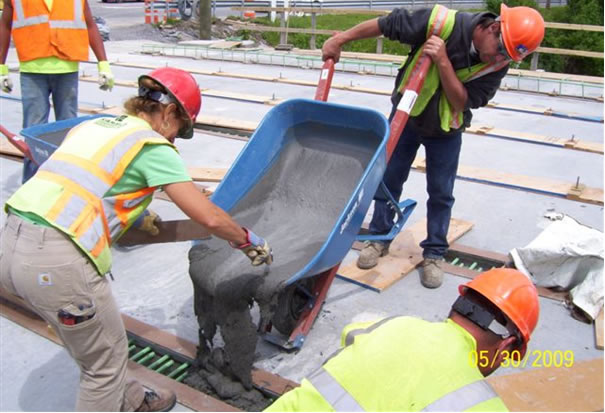
Figure 1. Placement of UHPC into longitudinal connection between deck–bulb–tee girders. The two fundamental differences between the field–cast UHPC connection concept and conventional modular component connection concepts are simplicity and performance. The UHPC connection concept allows for small, simple connections without requiring post–tensioning or large volumes of field–cast concrete. The performance of the connection exceeds that normally anticipated from a field–cast connection, thus allowing the joined components to emulate or surpass the behavior of monolithic construction.
UHPCAdvances in the science of concrete materials led to the development of the next generation of cementitious materials, namely UHPC. As a class, these concretes tend to contain high cementitious materials contents, very low water–to–cementitious materials ratios, compressive strengths above 22 ksi (150 MPa), and sustained tensile strength resulting from internal fiber reinforcement. Table 1 presents a select set of material properties for the type of UHPC investigated in this study. Further details on the mechanical and durability properties of this UHPC can be found in previous FHWA reports.(2) Table 1. Field-cast UHPC material properties.
The exceptional durability of UHPC has been well documented. Of particular importance, UHPC contains no coarse aggregate, so it does not exhibit the early–age microcracking common to conventional concrete. This, combined with the discontinuous pore structure in the homogeneous cementitious matrix, results in a concrete with an extremely low permeability. Tensile behavior of UHPC also stands in contrast to that of conventional concrete. The discrete steel fiber reinforcement included in UHPC components allows the concrete to maintain tensile capacity beyond cracking of the cementitious matrix. The inelastic straining of the component is resisted by fiber reinforcement that bridges the tight, closely spaced cracks. The durability and sustained tensile capacity of UHPC present opportunities to reimagine common concepts in reinforced concrete structural design. For example, the tensile capacity of UHPC could eliminate the need for discrete mild steel reinforcement in some structural members, and the durability could reduce the cover required for any remaining reinforcement.(3) Of particular interest, the mechanical properties of UHPC allow for the full development of discrete embedded reinforcements in exceptionally short distances. This behavior allows for the redesign of closure pours and other field–cast connections between modular components.
PHYSICAL TESTING PROGRAMThrough its Structural Concrete Research Program, the FHWA recently completed an experimental study focused on the performance of field–cast UHPC deck–level connections between precast modular bridge components. This study was part of Transportation Pooled Fund Project No. TPF–5(217), which is being completed in partnership with NYSDOT and the Iowa Department of Transportation. Bridge deck components simulating both longitudinal and transverse connections were fabricated and tested under both cyclic and static wheel patch loadings. Four transversely connected specimens simulated the connections between precast deck panels. These specimens were identical aside from the different discrete reinforcing details, which included straight lapped bars, headed bars, and intersecting hoop bars. The two longitudinally connected specimens simulated the connections between the top flanges of deck–bulb–tee girders. These two specimens were identical aside from the inclusion of two different discrete reinforcing details, namely straight lapped bars and lapped headed bars. Figure 2 provides details on the longitudinally connected specimen that included a straight bar non–contact lap splice connection.
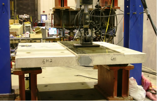
The tested components simulated a 94.5–by–84.7–inch (2.4–by–2.152–m) portion of a bridge deck that included a 6–inch (152–mm)–wide field–cast UHPC connection. The specimens were loaded on a simple span, with the load applied through a simulated wheel patch placed adjacent to the connection near midspan. Cyclic loads were applied first, with the test program including at least 2 million cycles to a load just below the cracking strength of the specimen followed by at least 5 million cycles to a load larger than the cracking strength of the specimen. After the completion of the cyclic testing, each test specimen was statically loaded to failure. Figure 3 shows one of the longitudinal connection specimens during cyclic loading.
The loading program was designed to allow for the assessment of three critical behaviors. First, the cyclic loading below the cracking load allowed for the assessment of the cracking performance of the field-cast UHPC and the bonding performance of the UHPC to precast concrete interface. Second, the cyclic loading that generated stresses above the static cracking stress of the specimen allowed for the assessment of the cracking performance of the system, including whether there was any uncontrolled, progressive cracking or any interface debonding. Finally, the loading program allowed for the assessment of the static overload performance of the system, thus providing an indication of whether the system effectively emulated the performance anticipated from a monolithic concrete deck. Due to the support and loading conditions applied to the subcomponent specimens, the cyclic loads generated stresses more severe than would traditionally be observed in a concrete bridge deck under similar magnitude wheel loads. A simple analytical study of the behavior of the transversely connected specimens suggests that the first phase of the cyclic testing with loads peaking at 16 kips (71 kN) generated stresses that are similar to the stresses that might be observed in a conventional concrete deck spanning 10 ft (3 m) between adjacent girders and loaded to a peak wheel patch load of 28 kips (125 kN). Subsequent cyclic testing with loads peaking at 21.3 kips (95 kN) generated even higher stresses and structural cracking of the decks.
CONCLUSIONSThe results of the test program, in combination with experience gained through deployments of field–cast UHPC–filled connections, have demonstrated the viability of this connection system. In terms of transverse deck connections, the structural behavior of the tested UHPC–filled connections emulated or surpassed the behaviors that would be anticipated from a monolithically cast concrete bridge deck. The cyclic responses demonstrated favorable cracking behavior with no interface debonding. The static loadings to failure resulted in global flexural failure of the simply–supported panels, with behaviors progressing through cracking, rebar yielding, and eventual concrete crushing. The study also demonstrated that the discrete reinforcement in the transverse and longitudinal UHPC–filled connections is not susceptible to debonding from the UHPC under conditions such as applied in this test program. In the most severe test, a longitudinally connected specimen was subjected to a large static overload and then 11.5 million subsequent cycles of structural loading at increasing load levels. Figure 4 shows the crack pattern observed on the underside of this specimen immediately after the overload. This crack pattern did not change throughout the subsequent cycling. The overload and subsequent cycling were not observed to cause any debonding of the straight lengths of rebar that were lapped across the connection.
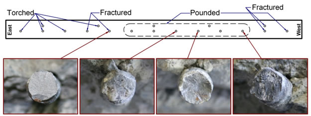
The development length of straight, uncoated No. 5 (16M) mild steel reinforcing bars in this test program was demonstrated to be equal to or less than 5.9 inches (150 mm) in a non-contact lap splice configuration within a field-cast UHPC-filled connection when subjected to flexural tensile loads. The cyclic loading demonstrated that when sufficiently large amplitude cyclic loads are applied, the stress range in the rebar can be sufficient to force the rebar to fail via metal fatigue. Figure 5 shows the cross section of the longitudinally connected specimen that failed due to progressive metal fatigue failure of the individual rebar crossing the connection interface. Each rebar labeled "Pounded" failed during the cyclic loading, resulting in repeated impact of mating surfaces. The other rebar failed as the specimen was being separated for posttest autopsy.
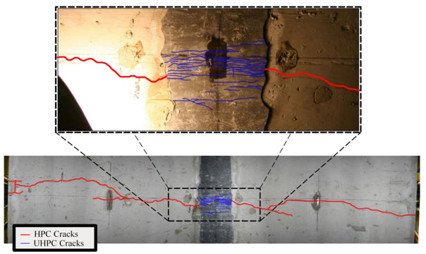
Structural cracks oriented perpendicular to a field–cast UHPC–filled connection tended to follow straight across the connection and did not turn to run along the concrete–to–UHPC interface. Additionally, when encountering the UHPC connection, single structural cracks in conventional concrete precast panels tended to become multiple, tightly spaced cracks in the field–cast UHPC. In the tests simulating transverse connections between precast components, the structural loads caused flexural tensile cracking perpendicular to the connection along midspan on the tensile face of each of the specimens. Crack widths were commensurate with the cracking behavior of the parent materials. In a general sense, an individual conventional concrete panel crack of a given width will lead into a set of approximately 10 cracks in the UHPC connection, each of which are on the order of 10 times narrower than the adjacent conventional concrete crack. This behavior can be observed in figure 6, which shows the cracking at midspan of a transversely connected specimen.
Finally, although a field–cast connection fill material that bonds well to precast components will alleviate one potential source of leakage, it cannot guarantee a leak–free deck. The favorable bond performance observed between the precast panels and the field–cast UHPC in transverse connection tests indicates that this bridge decking system is not likely to leak along this connection interface under cyclic service loads or static overloads. The longitudinal connection test results were less clear, indicating that the connection interface may or may not crack under large structural loads that approach or surpass the one–way bending flexural cracking capacity of the panel. Any structural cracking in a concrete bridge deck, whether monolithic or modular, provides a pathway of ingress for contaminants, which can lead to accelerated degradation of the deck system. Although these longitudinal connections are not necessarily leak–proof, their behaviors are likely to mimic or surpass the behaviors of a monolithic deck subjected to similar loads.
REFERENCES
FHWA-HRT-11-022 |