U.S. Department of Transportation
Federal Highway Administration
1200 New Jersey Avenue, SE
Washington, DC 20590
202-366-4000
Federal Highway Administration Research and Technology
Coordinating, Developing, and Delivering Highway Transportation Innovations
 | Report |  |
| This report is an archived publication and may contain dated technical, contact, and link information |
|
| Publication Number: FHWA-HRT-11-027 Date: JANUARY 2011 |
Publication Number: FHWA-HRT-11-027 Date: JANUARY 2011 |
The Geosynthetic Reinforced Soil (GRS) Integrated Bridge System (IBS) provides an economical solution to accelerated bridge construction. Employing this technology will help agencies save both time and money in planning and executing projects. This synthesis report and its companion document were developed to assist deployment of this promising technology as part of the Federal Highway Administration's (FHWA) Every Day Counts initiative.(1) This synthesis report provides the background and research behind the recommended design of GRS-IBS outlined in the interim implementation manual.(1) In-service performance of GRS-IBS and other GRS applications is also discussed through case histories.
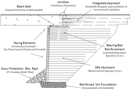
GRS-IBS is a fast, cost-effective method of bridge support that blends the roadway into the superstructure to create a jointless interface between the bridge and the approach (see figure 1). It consists of three main components: the reinforced soil foundation (RSF), the abutment, and the integrated approach. The RSF is composed of granular fill material that is compacted and encapsulated with a geotextile fabric. It provides embedment and increases the bearing width and capacity of the GRS abutment. It also prevents water from infiltrating underneath and into the GRS mass from a river or stream crossing. This method of using geosynthetic fabrics to reinforce foundations is a proven alternative to deep foundations on loose granular soils, soft fine-grained soils, and soft organic soils.(2) The abutment uses alternating layers of compacted fill and closely spaced geosynthetic reinforcement to provide support for the bridge, which is placed directly on the GRS abutment without a joint and without cast-in-place (CIP) concrete. GRS is also used to construct the integrated approach to transition to the superstructure. This bridge system therefore alleviates the "bump at the bridge" problem caused by differential settlement between bridge abutments and approach roadways.
Figure 1. Illustration. Typical GRS-IBS cross section.
Mark Twain said, "The ancients have stolen all our best ideas." Reinforced soil technology is not modern. The ancients used native material such as straw, tree branches, and plant material to reinforce the earth. The reinforcement provides tensile resistance to soil that is weak in tension but relatively strong in compression and shear. Through soil reinforcement interface bonding, the reinforcement restrains lateral deformation of the surrounding soil, increases its confinement, reduces its tendency for dilation, and consequently, increases the stiffness and strength of the soil mass.
In ancient Babylonia, the technology was used to construct the Aqar Quf ziggurat in Iraq around 1440 B.C. The stepped pyramid was built using compacted layers of plant material and soil blocks. The Great Wall of China also used reinforced earth to construct some sections. The fact that these structures are still visible today is a tribute to the durability of reinforced soil technology.
Modern reinforced soil technology has evolved into two primary methods for the stabilization of earth: mechanically stabilized earth (MSE) and GRS. Today, the predominant method of building reinforced soil is MSE, established in the early 1960s when Henri Vidal patented Reinforced Earth®. The method incorporates discrete steel strips embedded within a soil mass. Since then, other types of reinforcement materials, classified as either inextensible or extensible, have been used to reinforce earth. Berg et al. defined inextensible reinforcement as a material that deforms considerably less than the surrounding soil at failure and extensible reinforcement as a material that deforms as much as the surrounding soil.(3) In fact, MSE technology has branched off into two primary pathways: proprietary structures built with metallic (inextensible) reinforcements and proprietary structures built with geosynthetic (extensible) reinforcements.
MSE structures built with inextensible reinforcement such as discrete metallic strips or welded wire mats have a unique combination of precast panels, reinforcement, and connection details. The vertical spacing of the reinforcement (Sv) is typically about 30 inches, and the typical size of the precast panels is about 5 ft high by 5 to 10 ft wide (see figure 2 and figure 3).
Figure 2. Photo. MSE inextensible reinforcement—steel strips.(3)
Figure 3. Photo. MSE inextensible reinforcement—wire mats.(3)
MSE structures built with extensible reinforcement such as geosynthetics were introduced in the mid-1980s when geogrids were used to reinforce or stabilize the fill behind structures constructed with concrete modular blocks (see figure 4). Today, these proprietary modular block structures are typically built with a unique combination of the block, geogrids, and connection details. The vertical spacing of the reinforcement (Sv) is typically 24 inches, or one layer of reinforcement for every three courses of 8-inch modular block facing. The facing block has typical dimensions of 8 inches by 16 inches by 12 inches and a weight of about 80 lb.
Figure 4. Photo. MSE extensible reinforcement (geogrid).
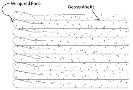
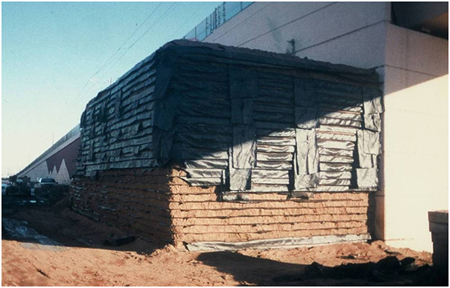
The first documented use of alternating layers of geosynthetic and soil, referred to as GRS technology, was by the U.S. Forest Service in the 1970s.(4) The Forest Service used the technology to build logging roads on steep mountain terrain. These GRS structures utilized a wrapped face—the geosynthetic was wrapped up and around the face of the individual soil layers and anchored by the overburden of the subsequent layer of soil (see figure 5). Many of these wrapped-face GRS structures (also called burrito walls) are still in service.
Figure 5. Illustration. Typical wrapped-face GRS structure.
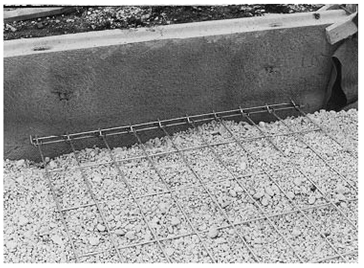
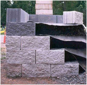
Later, the Colorado Department of Transportation (CDOT) developed a low-cost generic wall system using lightweight concrete modular blocks. Rather than securing the blocks to the reinforcement with connections, as in MSE technology, the concrete facing blocks were frictionally connected to the GRS mass (see figure 6). The interface between the blocks and the geosynthetic provided enough friction to resist block movement. This method of connection in combination with closely spaced reinforcement layers created a facing system that adjusts to relieve stress without attracting loads. The FHWA refined the CDOT method to account for vertical load-bearing applications, resulting in the development of GRS abutments, followed by GRS-IBS (see figure 1).(5,6)
Figure 6. Photo. Cut-away of GRS mass.
GRS-IBS was initially developed by FHWA during the Bridge of the Future initiative to help meet the demand for the next generation of small, single span bridges in the United States. GRS-IBS can be built with lower cost, faster construction, and potential improved durability and can be used to build bridges on all types of roads, on or off the National Highway System.
As of 2010, 45 bridges utilizing GRS abutments had been built in the United States. Of these bridges, IBS had been employed on 28 bridges, all built over water crossings. The hydraulic environments at these locations is such that scour is shallow, making the system feasible for these sites. Refer to the interim implementation manual for special hydraulic design requirements before selecting a water crossing for GRS-IBS deployment.(1)
GRS abutments built with a reinforcement spacing less than or equal to 12 inches behave as a composite mass with predictable behavior. They can be built to economically support a bridge superstructure bearing directly on the reinforced soil behind the facing block. GRS can be used to integrate the superstructure with the approach and substructure to create a jointless bridge system (GRS-IBS).
Many studies have been conducted on the composite behavior of GRS structures. These investigations have concluded that existing design methods do not adequately characterize the interactive behavior between the soil and the closely spaced reinforcement of a GRS abutment.(3,7) As a result, the interim implementation manual was developed.(1) The manual is largely based on the observed composite behavior of GRS and is substantiated by empirical evidence of in-service GRS-IBS.
A degree of composite behavior results from reinforcement frequency. For larger-spaced reinforced soil systems, the composite behavior diminishes with increased reinforcement spacing. It is important to note that the transition into GRS behavior is not dependent solely on reinforcement spacing; the aggregate size and friction angle are also contributing factors, as explained in chapter 3.
Closer reinforcement spacing creates more soil-geosynthetic interaction. In GRS, the reinforcement not only serves to resist tensile forces but also functions to restrain lateral deformation of the soil, increase lateral confinement of the soil, generate apparent cohesion in a granular fill (while maintaining all desirable characteristics of granular soil), suppress dilation of the soil, enhance compaction-induced stresses, increase ductility of the soil mass, and reduce migration of fines, depending on the reinforcement type selected. These added benefits develop because of the close reinforcement spacing.
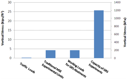
The frequency of reinforcement spacing in GRS allows for compaction of the soil directly behind the facing, producing the capacity for load bearing at this location. The spacing of the reinforcement also has a significant impact on the strength and behavior of GRS performance. This is illustrated in figure 7, which shows the load-carrying capacity of GRS with a typical spacing of 8 inches.(8) The figure shows that working loads for bridges are about 4 ksf.(9) The ultimate capacity of GRS, however, can be as high as 25 ksf. The ultimate capacity of GRS is a function of the reinforcement spacing, the reinforcement strength, and the soil conditions, including maximum particle size and friction angle.
Figure 7. Graph. General comparison of surcharges on MSE and GRS structures.
The ultimate capacity of GRS is influenced more by the reinforcement spacing than by the reinforcement strength (Tf).(10) This is apparent in the results from large-scale tests, shown in table 1. The results indicate that the response is not the same at the same Tf/Sv ratio. The strength of the GRS mass is 1.5 times higher and the stiffness 1.3 times higher at lower spacing and reinforcement strength (test 2) than at higher spacing and reinforcement strength (test 3). Reduced spacing at equal reinforcement strengths (tests 2 and 4) increases the strength of the GRS mass by 2.1 times and the stiffness by 1.3 times. Increasing the reinforcement strength at equal spacing, however, only increases the strength of the GRS mass by 1.4 times and the stiffness by 1.0 times (tests 3 and 4). This shows that spacing has a larger effect than reinforcement strength.
Table 1. Large-scale GRS tests.(10)
Test |
Reinforcement |
Confining Stress |
Ultimate Applied Vertical Load |
Modulus at 1 Percent Vertical Strain |
Strain at Failure |
||
|---|---|---|---|---|---|---|---|
Spacing |
Strength |
Ratio |
|||||
Sv |
Tf |
Tf/Sv |
σc |
qult |
E @ ε v = 1% (ksf) |
v (Percent) |
|
1 |
– |
4,800 |
– |
0.7 |
16 |
700 |
3 |
2 |
8 |
4,800 |
600 |
0.7 |
56 |
1,300 |
6.5 |
3 |
16 |
9,600 |
600 |
0.7 |
36.5 |
1,000 |
6.1 |
4 |
16 |
4,800 |
300 |
0.7 |
27 |
970 |
4 |
5 |
8 |
4,800 |
600 |
0.0 |
40 |
1,100 |
6 |
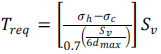
Since the reinforcement strength and spacing are not proportional, a new equation for required reinforcement strength was needed. The analytical equation shown in equation 1 was developed by Wu et al. to incorporate the effect of confinement (i.e., facing rigidity, σc), reinforcement spacing, and aggregate size (dmax).(10) The equation has been validated against numerous large-scale experiments that were tested to failure (see appendix B). Equation 1 will be discussed in detail in chapter 3.
The required reinforcement strength calculated using equation 1 accounts for compaction-induced stresses (CIS), which increase the lateral stress in a GRS mass.(10) CIS are locked in and stiffen the composite. This increased lateral stress must be overcome in order to initiate movement of the GRS mass.
In addition to calculating the required reinforcement strength, a factor of safety (or reduction factor) is necessary to reduce the ultimate strength of the reinforcement used in design. In current design, cumulative reduction factors for geosynthetics made of polypropylene have practically precluded their use in permanent GRS structures.(3) Numerous case histories and field observations have proven, however, that geotextiles can successfully be implemented in several applications, including walls and abutments.(10–13)
Because a GRS structure is a composite mass, the use of cumulative reduction factors for the long-term strength of the reinforcement by itself is unnecessary. A single factor of safety of 3.5 (or resistance factor of 0.4) for ultimate reinforcement strength should be used, which accounts for long-term degradation (creep, durability, and installation damage). This recommended value is derived from the cumulative long-term reduction factors for a GRS mass in conjunction with an overall uncertainty factor of 2.0.(14,10) This factor of safety is based on the results of several tests conducted on different reinforcement materials within soil, including accelerated creep tests.(15)
Note that creep deformation of a GRS wall is the result of soil-geosynthetic interaction. If the backfill has a tendency to creep faster than the geosynthetic reinforcement, the creep rate of the geosynthetic reinforcement will accelerate. Conversely, if the backfill has a tendency to creep slower than the geosynthetic reinforcement, the creep rate of the geosynthetic reinforcement will become smaller. For a GRS wall with a well-compacted granular backfill, the time-dependent deformation will be very small, and the rate of deformation will typically decrease rapidly with time (the geosynthetic cannot creep by itself). This means that creep will cease soon after construction. Moreover, the tensile forces induced in geosynthetic reinforcement at working stresses are typically very small due to stress redistribution. The very small tensile forces also contribute to very small creep deformation. GRS tests have shown that the soil and reinforcement strain together because the lower spacing confines the soil.(14)
For the recommended granular fill, damage to the reinforcement is not a concern.(1) If large aggregate particles (greater than 3 inches in diameter) are used, however, considerable damage to the reinforcement may occur. This would require reevaluation of the combined effects and may necessitate the use of a heavier reinforcement with a greater tensile strength. Such a situation is not discussed in this report.
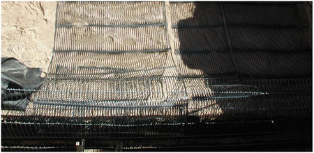
The base-to-height (B/H) ratio can be reduced to as low as 0.3 as long as external stability is satisfied.(16,17) This is because a GRS mass is freestanding and internally stable. Internally supported systems stabilize a soil mass by the inclusion of the reinforcement alone.(10) Figure 8 shows a stable, internally supported GRS mass without a facing.
Figure 8. Photo. Internally supported GRS structure.
The facing elements of a GRS abutment are not required for structural support and do not carry any appreciable load. GRS facing blocks are primarily a construction aid to provide a form for each lift of compacted fill, a protective barrier, and a façade for aesthetic purposes. To ensure that the face is not loaded, the superstructure is placed with a certain setback and clear space as recommended in the interim implementation manual.(1)