Post-Earthquake Reconnaissance Report on Transportation Infrastructure: Impact of the February 27, 2010, Offshore Maule Earthquake in Chile
CHAPTER 4. STRUCTURAL PERFORMANCE OF HIGHWAY BRIDGES
4.1 OVERVIEW
General observations of damage to highway bridges are reported in this chapter. The bridges are organized according to bridge type, such as concrete and steel girder superstructures, arches, and trusses. They are further divided into regular and irregular structures in terms of skew angle and curvature. The bridge site numbers are provided for reference.
The following bridges are discussed in section 4.2, Performance of Straight Concrete Bridges:
- Independencia (sites 6a–6d).
- Avenida Chada (site 8).
- Las Mercedes (site 12).
- Llacolen (site 17).
- Juan Pablo II (site 25).
- Ramadillas (sites 24a and 24b).
The following bridges are discussed in section 4.3, Performance of Skewed and Curved Concrete and Steel Bridges:
- Miraflores (sites 1a and 1b).
- Lo Echevers (sites 2a and 2b).
- Avenida Romero (site 7).
- Route 5 railway overcrossing at Hospital (sites 10a and 10b).
- Matta Quilicura (site 5).
The following bridges are discussed in section 4.4, Performance of Straight Steel Bridges:
- Tubul (site 22).
- Cardenal Raúl Silva Henríquez (site 16).
- Biobío River (old) (site 26).
- Pichibudis (site 14).
- El Bar (site 23).
- Itata (site 30).
- Pedestrian bridge over Route 5 (site 4).
Lastly, the following bridges are discussed in section 4.5, Performance of Other Bridge Types:
- Claro River (sites 13a and 13b).
- Chepe railroad bridge over Biobío River (site 18).
- Maipú River (sites 9a–9c).
4.2 PERFORMANCE OF STRAIGHT CONCRETE BRIDGES
4.2.1 Américo Vespucio/Independencia
Two bridges oriented in the east-west direction and two ramps connected to westbound traffic were inspected at this site. The eastbound bridge, built in 2004, is a four-span structure with five discontinuous precast prestressed girders and a continuous deck. It almost collapsed during the earthquake, experiencing a lateral offset of greater than 1.6 ft (0.5 m), as indicated by the use of temporary heavy supports shown in figure 23 through figure 25. The superstructure had steel stoppers but no intermediate or end diaphragms. As shown in figure 24 and figure 25, both the curtain wall of the abutment and the steel stoppers were significantly damaged. Each stopper was anchored with two bolts embedded in the cap beam at a depth of 35 inches (900 mm), as shown in figure 26. Steel stoppers were mainly used to restrain the vertical movement of girders.
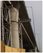
Figure 23. Photo. Damage to eastbound Independencia bridge.
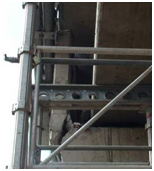
Figure 24. Photo. Curtain wall at east abutment of eastbound Independencia bridge.
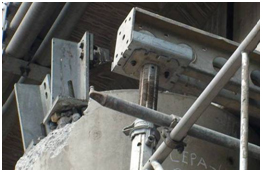
Figure 25. Photo. Damage to steel stoppers on eastbound Independencia bridge.
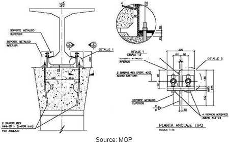
Figure 26. Illustration. Details of steel stoppers.
The westbound bridge, built in 1997, is a four-span structure with six discontinuous precast prestressed girders and a continuous deck. Each bent has two flared wall piers, as shown in figure 27. The bridge was designed with both intermediate and end diaphragms. The bridge survived the earthquake with excessive deformations in the seismic bars and damage to concrete shear keys at abutments and intermediate bents (see figure 28 through figure 30).
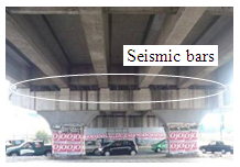
Figure 27. Photo. Typical flared wall pier of westbound Independencia bridge.
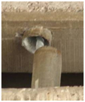
Figure 28. Photo. Displaced seismic bar on westbound Independencia bridge.
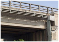
Figure 29. Photo. Shear key damage at abutment of westbound Independencia bridge.
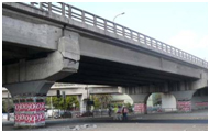
Figure 30. Photo. Shear key damage at intermediate bents of westbound
Independencia bridge.
In comparison to the eastbound bridge, the presence of diaphragms seems to have helped maintain the structural integrity of the westbound bridge. More importantly, the concrete shear keys of the westbound bridge served their design purpose during the earthquake, as opposed to the steel stoppers in the eastbound bridge. No visible foundation damage was observed for either structure.
Additional views of the shear key damage in the westbound bridge and its entrance ramp are shown in figure 31 through figure 33. As shown in figure 31, shear key failures occurred in almost the entire structure. The entrance ramp next to the bridge is supported on two hammerhead piers at the intermediate bents, as shown on figure 32. The shear keys at the abutment were damaged. Figure 33 shows an approximately 1.5-inch (38-mm)-wide gap between the abutment and the surrounding soil caused by strong ground shaking.
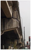
Figure 31. Photo. Westbound Independencia bridge.
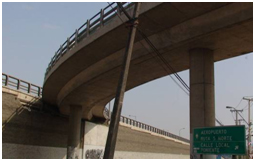
Figure 32. Photo. Entrance ramp to westbound Independencia bridge.
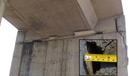
Figure 33. Photo. Shear key damage at entrance ramp abutment.
The exit ramp for westbound traffic remained in service after the earthquake. Minor damage due to pounding in the corner of the beam recess was observed on a flared wall pier close to the westbound bridge, as shown in figure 34 and figure 35.
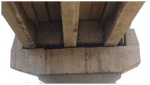
Figure 34. Photo. Flared wall pier of exit ramp from westbound Independencia bridge.
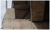
Figure 35. Photo. Close-up of damage to exit ramp from westbound Independencia bridge.
4.2.2 Avenida Chada Acceso Sur Overpass
The two-span Chada overpass, shown in figure 36 through figure 39, is oriented approximately east-west. The bridge superstructure was displaced significantly and rotated counterclockwise in plan during the earthquake. The transverse offset between the deck and abutment seats ranged from 25 to 30 inches (640 to 780 mm). The longitudinal gap between the end of girders and the abutment was 3.5 inches (90 mm). The bottom flange and web of the exterior precast girder that hit the curtain walls at each abutment failed in shear, as shown in figure 36. The failure of the bottom flange can be seen in figure 37. The two curtain walls at the intermediate bent were both damaged, as shown in figure 38. The bridge experienced strong shaking, indicated by an induced gap around the columns, as shown in figure 39. No structural damage was observed in the bridge columns.
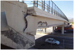
Figure 36. Photo. Curtain wall shear failure at abutment of Chada bridge.
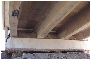
Figure 37. Photo. Bottom flange damage to Chada bridge.
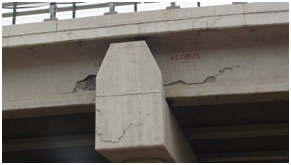
Figure 38. Photo. Curtain wall damage at bent of Chada bridge.
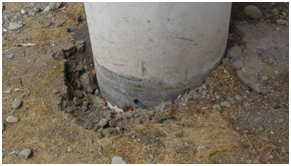
Figure 39. Photo. Soil separation from column of Chada bridge.
Although the bridge is not skewed, significant rotation was observed in its superstructure, as illustrated in figure 40. In the absence of restraint at the abutments (i.e., no diaphragm), the period of the rotational mode of vibration was shorter than the translational modes and appeared to have been strongly excited in the earthquake either by the translational components of the ground motion or by the rotational component. If the former, some degree of eccentricity between the centers of mass and stiffness would need to be present, which is quite likely given the slumping of the abutment fills and the duration of shaking.
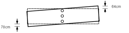
1 cm = 0.39 inches
Figure 40. Illustration. Plan view of superstructure rotation of Chada bridge.
4.2.3 Las Mercedes Route 5 Overpass
The two-span Las Mercedes overpass is oriented approximately east-west and is a concrete-girder structure with a slight skew, as shown in figure 41. The superstructure comprises three precast prestressed girders and is supported on a two-column intermediate bent and two seat-type abutments, all resting on drilled shafts. Two seismic bars (deformed rebar) were installed between pairs of adjacent girders at all supports. Like the Chada bridge, the Las Mercedes bridge experienced a significant counterclockwise rotation during the earthquake. The exterior girders rotated off their abutment seats at both ends, resulting in a longitudinal crack between the exterior and interior girders in the deck slab.
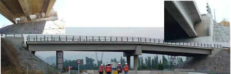
Figure 41. Photo. Las Mercedes bridge and girder unseating at abutments.
In addition, one transverse crack across the bridge deck was observed at the intermediate bent. The curtain walls were severely damaged when struck by the bridge superstructure. Temporary supports were provided for the unseated exterior girders, as shown in figure 41.
4.2.4 Llacolen Bridge Over Biobío River
The Llacolen bridge, a major crossing over the Biobío River in Concepción is oriented approximately northeast-southwest and is a multispan, simply supported concrete girder bridge. Each span consists of a deck slab and six precast prestressed girders that are supported on two five-column bents with an inverted-T cap beam. Two seismic bars are provided between each pair of adjacent girders. Figure 42 shows a general view of the bridge.
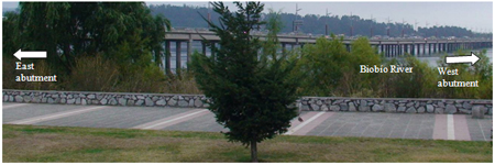
Figure 42. Photo. Llacolen bridge looking south-southwest.
As shown in figure 43, a simply supported span in the eastern approach to the bridge dropped from its seat at the river end of the span, and a temporary Bailey bridge was erected to give traffic access to the main crossing. As shown in figure 44, the end bent supporting the unseated span remained intact except for concrete spalling underneath the cap beam, as shown in figure 45. The seismic bars shown in figure 44 were deformed almost 180 degrees as the span collapsed and they were pulled from the diaphragms. The columns supporting the cap beam experienced flexural cracks at the level of the rock rip rap on the bank below the bridge (see figure 46 and figure 47). The cracks appeared on the river side of the columns, where tension developed as the superstructure held the columns against the lateral movement imposed on the foundations by liquefaction-induced lateral spreading of the banks. The bent and columns at the opposite end of the unseated span were undamaged. However, as shown in figure 48, the nearby ground settled up to 1.3 ft (0.4 m) and experienced significant shaking, resulting in a 0.82-ft (0.25-m) separation between the columns and their surrounding ground.
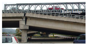
Figure 43. Photo. Unseated simply supported span in eastern approach to Llacolen bridge.
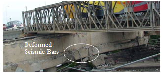
Figure 44. Photo. Abutment at unseated end of span in eastern approach to Llacolen bridge.
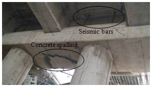
Figure 45. Photo. Concrete spalling beneath cap beam of eastern approach to Llacolen bridge.
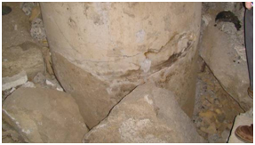
Figure 46. Photo. Flexural cracks at the level of rip rap on eastern approach to Llacolen bridge.
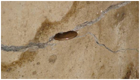
Figure 47. Photo. Close-up view of cracks at the level of rip rap on eastern approach to Llacolen bridge.
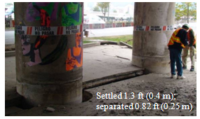
Figure 48. Photo. Ground settlement and lateral movement of eastern approach to Llacolen bridge.
The entrance ramp for westbound traffic is a three-span simply supported box girder bridge. The girders are supported on wall piers with neoprene pads and fitted with seismic bars. The ramp was almost unseated at the river end of the last span, as shown in figure 49 and figure 50. At one intermediate bent, the seismic bars were rusty and the neoprene pads had degraded, as shown in figure 51 through figure 53.
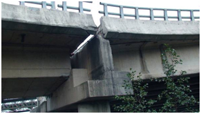
Figure 49. Photo. Exterior face of westbound ramp to Llacolen bridge at the river end.
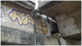
Figure 50. Photo. Interior face of westbound ramp to Llacolen bridge at the river end.
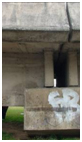
Figure 51. Photo. Bent of westbound ramp to Llacolen bridge.
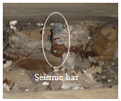
Figure 52. Photo. Seismic bar condition on westbound ramp to Llacolen bridge.
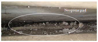
Figure 53. Photo. Neoprene pad degradation on westbound ramp to Llacolen bridge.
At the west end of the Llacolen bridge, soil settlement and liquefaction were observed at multiple locations near the bridge bents, as shown in figure 54 and figure 55. Pounding-induced damage was also observed at the supports of precast girders, as shown in figure 56 and figure 57. Minor damage also occurred when the girders engaged the concrete keys on the west abutment (see figure 58).
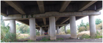
Figure 54. Photo. Columns with soil marks indicating ground settlement
at west end of Llacolen bridge.

Figure 55. Photo. Sand boils near columns at west end of Llacolen bridge.
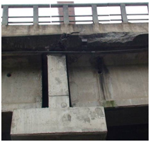
Figure 56. Photo. Spalling in deck slab at west end of Llacolen bridge.
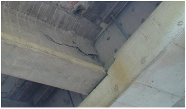
Figure 57. Photo. Horizontal crack in web of end girders at west end of Llacolen bridge.
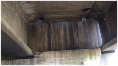
Figure 58. Photo. Spalling of shear key at southwest abutment of Llacolen bridge.
4.2.5 Juan Pablo II Bridge Over Biobío River
The Juan Pablo II bridge is another major crossing over the Biobío River in Concepción. It is oriented northeast-southwest. The northern approach to this bridge is part of an interchange that provides access to the bridge from a riverfront highway, as shown in figure 59. In addition to exit and entrance ramps, the interchange comprises a two-span approach structure and a two-span highway overpass. Each bridge superstructure consists of discontinuous precast prestressed girders and a continuous deck.
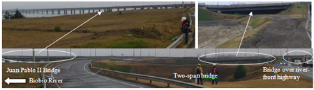
Figure 59. Photo. Approaches to Juan Pablo II bridge.
Although the riverfront overpass was generally undamaged, the two-span approach structure was damaged both globally and locally at the intermediate bent. As shown in figure 60 through figure 62, the intermediate bent had settled with respect to the two end bents, leading to a substantial depression in the roadway surface. This intermediate bent comprises two rectangular columns that most likely experienced uneven liquefaction-induced settlement during the earthquake (see figure 63). The consequential change in stiffness between the two columns shifted the longitudinal seismic force from one column to the other, which then failed in shear, as shown in figure 64. The transverse reinforcement of the failed column was spaced at 17.8 inches (457 mm). Figure 65 and figure 66 show the soil surface prior to the earthquake on the face of undamaged column and cracking in the cap beam above.
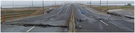
Figure 60. Photo. Southwest view of northern approach to Juan Pablo II bridge, facing Biobío River.
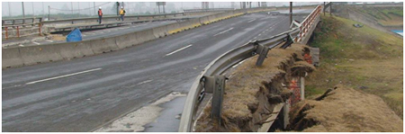
Figure 61. Photo. Northeast view of northern approach to Juan Pablo II bridge, facing away from Biobío River.
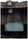
Figure 62. Photo. Intermediate bent of northern approach to Juan Pablo II bridge.
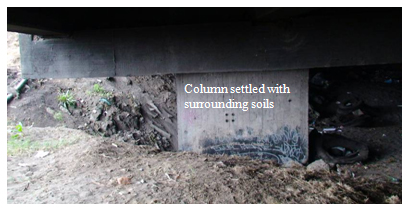
Figure 63. Photo. Column settlement under approach to Juan Pablo II bridge (cracks on far side).
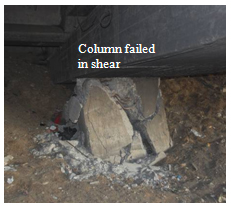
Figure 64. Photo. Reduced column height due to shear failure under approach to Juan Pablo II bridge.
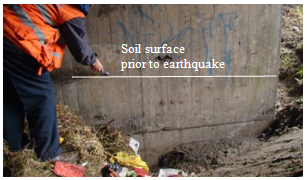
Figure 65. Photo. Soil surface on far side of undamaged column under approach to Juan Pablo II bridge.
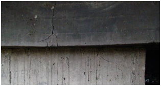
Figure 66. Photo. Cracks on far side of undamaged column under approach
to Juan Pablo II bridge.
Consistent with the behavior of the approach structure, the spans of the main bridge also appeared to have experienced uneven support settlement, which tilted the columns and rotated the bridge deck about the centerline of the bridge, as seen in figure 67.
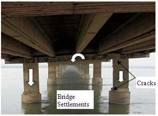
Figure 67. Photo. Differential settlement underneath first span over water at northern end of Juan Pablo II bridge.
In addition, lateral spreading of the northeast bank pushed the columns of the bent toward the river. However, this movement was restrained by the superstructure, and the columns were consequently placed in single shear. One failed catastrophically (see figure 68 through figure 70), and the other was seriously damaged (see figure 71). The difference in behavior between the two columns might have been due to the uneven settlement and rotation of the bridge deck. The longitudinal movement of the first column was approximately 21.8 inches (559 mm) at the top of the shear plane and 15.8 inches (406 mm) at the bottom. Similar behavior was also observed in the Llacolen bridge, but the damage to the columns was not as severe.
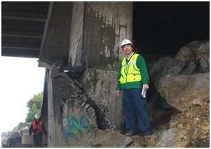
Figure 68. Photo. Shear failure in upstream column at northern end of Juan Pablo II bridge.
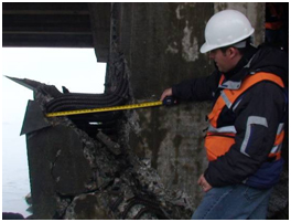
Figure 69. Photo. Front face of failure plane at northern end of Juan Pablo II bridge.
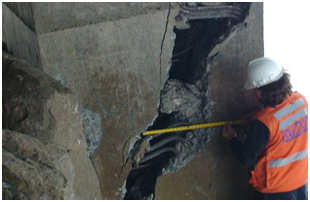
Figure 70. Photo. Back face of failure plane at northern end of Juan Pablo II bridge.
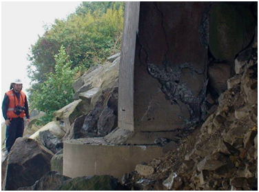
Figure 71. Photo. Shear failure in downstream column at northern end
of Juan Pablo II bridge.
4.2.6 Ramadillas Bridges
Two bridges cross the Piteateo River close to the town of Ramadillas in Arauco (see figure 72). The bridges are generally oriented north-south. The east bridge is a relatively new structure with total length of approximately 853 ft (260 m) comprising eight spans spaced at 105 ft (32 m). The superstructure is composed of three parallel precast prestressed girders simply supported between piers and a reinforced concrete deck. The substructure is composed of two seat-type abutments and seven intermediate wall-type piers (see figure 73 and figure 74). Reinforced concrete diaphragms are used at each abutment and intermediate pier with vertical restrainers and shear keys. This structure has two lanes, one for each direction of traffic.
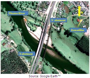
© Google and GeoEye
Figure 72. Photo. Satellite image of Ramadillas bridges.

Figure 73. Photo. Side view of east Ramadillas bridge.
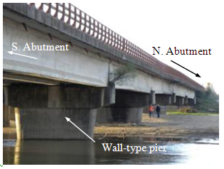
Figure 74. Photo. Wall-type pier beneath east Ramadillas bridge.
During the earthquake, the piers near the river settled due to liquefaction, causing vertical misalignment of the deck, as shown in figure 75. Sand boils appeared at the bottom of some piers, as shown in figure 76.
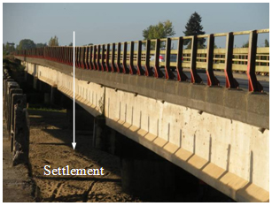
Figure 75. Photo. Deck misalignment under east Ramadillas bridge.
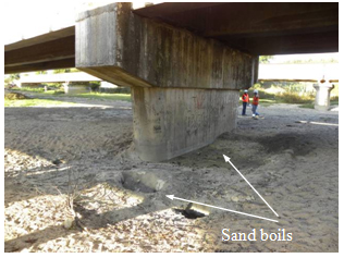
Figure 76. Photo. Sand boils close to pier under east Ramadillas bridge.
The west Ramadillas bridge is an older structure that was closed to vehicular traffic at the time of the earthquake. The total length is approximately 850 ft (260 m) with 14 spans of about 60.7 ft (18.5 m). The superstructure is composed of four parallel steel girders simply supported at the piers and a reinforced concrete deck. The substructure is composed of two seat-type abutments and 13 intermediate wall-type piers (see figure 77 and figure 78). Steel X-braced cross frames were provided at the ends of each span as well as at midspan locations. The girders were anchored to the piers by two anchor bolts, one on each side of the bottom flange.
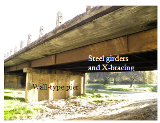
Figure 77. Photo. Overview of west Ramadillas bridge.
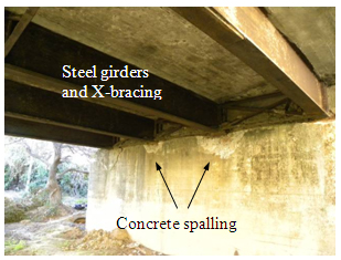
Figure 78. Photo. Abutment damage beneath west Ramadillas bridge.
In addition to large inertial forces, significant settlement and lateral flow occurred due to liquefaction during the earthquake. As a consequence, one of the wall piers tilted significantly, and the adjacent span was unseated, as shown in figure 79 and figure 80.
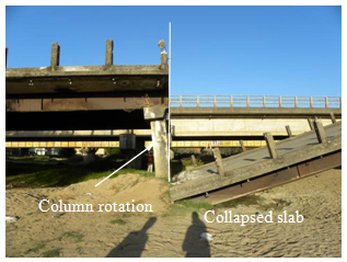
Figure 79. Photo. Pier rotation in collapsed span of west Ramadillas bridge.
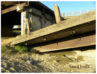
Figure 80. Photo. Sand boils near collapsed span in west Ramadillas bridge.
The largest settlements and lateral flows were observed in the river bank under the south abutments of both bridges. Figure 81 through figure 83 show the extent of these effects.
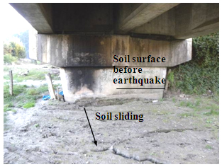
Figure 81. Photo. Settlement at south abutment under east Ramadillas bridge.
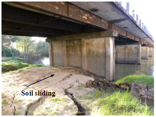
Figure 82. Photo. Sliding at south abutment under west Ramadillas bridge.
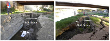
Figure 83. Photo. Block flow toward river due to liquefaction on south bank of Ramadillas bridges.
4.3 PERFORMANCE OF SKEWED AND CURVED CONCRETE AND STEEL BRIDGES
4.3.1 Américo Vespucio/Miraflores
At the Miraflores bridge site, two parallel bridges collapsed, as shown in figure 84 through figure 88. These bridges for southwest-bound and northeast-bound traffic did not have end diaphragms and appear to have had an S-shaped superelevation. Each three-span precast prestressed girder bridge had five discontinuous girders and a continuous deck slab. The abutments and two intermediate piers were skewed to approximately 20 degrees. Each girder was supported on a neoprene pad and a concrete pedestal at both ends. The girders were restrained by a pair of steel stoppers with 0.4- and 2-inch (10- and 50-mm) gaps for vertical and horizontal motions. Details of the steel stoppers are shown in figure 26.
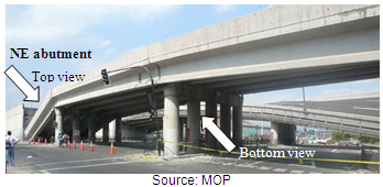
Figure 84. Photo. Northeast end of Miraflores bridge.
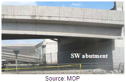
Figure 85. Photo. Southwest end of Miraflores bridge.
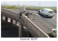
Figure 86. Photo. Top view of Miraflores bridge from far side.
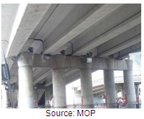
Figure 87. Photo. Bottom view of Miraflores bridge from near side.
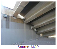
Figure 88. Photo. Collapsed span of Miraflores bridge.
During the earthquake, one end span of each bridge fell from its seat-type abutment support. The other end span of one bridge was partially unseated. After the spans were removed, it was clear that the entire bridge superstructure rotated clockwise in plan as the acute corner of the bridge moved away from its supporting abutment (see figure 89 through figure 91). As a result, the curtain walls on all abutments suffered damage in the acute corners. The steel stoppers experienced little bending deformation, but their anchor bolts were either substantially deformed or sheared off.
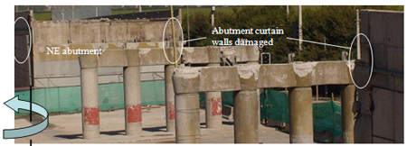
Figure 89. Photo. Miraflores bridge after removal of superstructure.
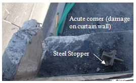
Figure 90. Photo. Acute corner of southwest abutment of Miraflores bridge.
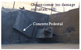
Figure 91. Photo. Obtuse corner of southwest abutment of Miraflores bridge.
4.3.2 Américo Vespucio/Lo Echevers
At the Lo Echevers bridge site, two parallel bridges had spans of 91.3, 119.1, and 91.3 ft (27.84, 36.32, and 27.84 m). As shown in figure 92 and figure 93, the southwest-bound bridge suffered minor damage while the northeast-bound bridge collapsed. The bridges did not have end diaphragms and appeared to have had an S-shaped superelevation. Each three-span precast prestressed girder bridge had five discontinuous girders and a continuous deck slab. The abutments and two intermediate piers were skewed approximately 33 degrees. Each girder was supported on a neoprene pad and a concrete pedestal at both ends. The girders were restrained by a pair of steel stoppers with 0.4- and 2-inch (10- and 50-mm) gaps for vertical and horizontal motions. Details of the steel stoppers are shown in figure 26.
Figure 92. Photo. Collapsed northeast-bound Lo Echevers bridge.
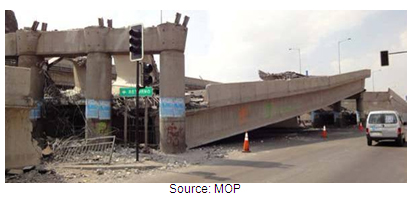
Figure 93. Photo. Three unseated spans of northeast-bound Lo Echevers bridge.
During the earthquake, the bridge superstructure rotated clockwise in plan as the acute corners of the bridge moved away from their supporting abutments. Some of the anchor bolts fractured, as shown in figure 94, and the elastomeric bearings seemed to have been displaced during the earthquake, as shown in figure 95. These bearings showed significant lateral bulging and may have been overstressed under gravity loads.
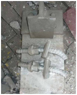
Figure 94. Photo. Failure of a steel stopper on Lo Echevers bridge.
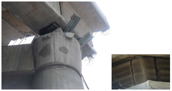
Figure 95. Photo. Displaced elastomeric bearing on Lo Echevers bridge.
Since the two bridges seem identical and experienced similar ground motion, it was unclear from visual inspection why one collapsed and the other did not. A numerical analysis of a complete model of the bridge may better explain the damage pattern.
4.3.3 Avenida Romero Acceso Sur Overpass
The Romero overpass is a two-span bridge with discontinuous precast prestressed girders, a continuous deck slab, and spans of 96.8 ft (29.5 m) each. Oriented approximately east-west, the bridge is similar to the Chada overpass described in section 4.2.2 except that it has a skew angle of 31.3 degrees. The bridge has five girders but no diaphragms. Two seismic bars were provided between each pair of adjacent girders. As shown in figure 96, the intermediate bent has four columns that are supported by four drilled shafts with a pile cap between the columns and the drilled shaft foundation. Each abutment also rests on four drilled shafts. During the earthquake, the superstructure moved toward the west abutment and rotated counterclockwise away from the acute corner of the bridge. Both spans were unseated at their abutments, as shown in figure 97, which also shows lateral shear failures that occurred in the webs of the exterior girders over the bent due to excessive transverse loads.
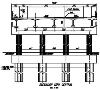
Figure 96. Illustration. Intermediate bent details for Romero bridge.
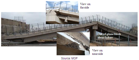
Figure 97. Photo. Collapse of Romero bridge.
These observations are supported by the pounding marks on the west abutment, the damage pattern in the curtain walls of the two abutments, and the orientation of the remaining seismic bars at the intermediate bent and two abutments, as shown in figure 98 through figure 100. Figure 101 shows damage to the back wall and wing wall resulting from the girder impact on the west abutment. This damage pattern may have resulted from the combined effects of ground motion characteristics and the skew configuration. More specifically, the rotational mode of vibration of the bridge seemed very sensitive to the ground motions, which can be augmented by the skewed abutments. In addition, rotational ground motion is another plausible reason for superstructure rotation but needs to be verified by examination of the ground motion records.
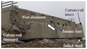
Figure 98. Photo. Seismic bars at west abutment of Romero bridge.
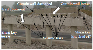
Figure 99. Photo. Seismic bars at east abutment of Romero bridge.
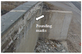
Figure 100. Photo. Pounding at west abutment of Romero bridge.
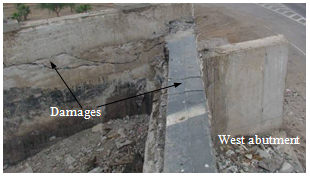
Figure 101. Photo. Back wall and wing wall damage at west abutment of Romero bridge.
4.3.4 Route 5 Railway Overcrossing at Hospital
The Route 5 railway overcrossing at Hospital comprised three parallel bridges over two railway tracks and a local road. The bridges were oriented northwest-southeast. One bridge had a steel plate girder superstructure, and the other two had precast prestressed girders. The two concrete bridges carried northbound and southbound traffic on Route 5. During the earthquake, the southbound bridge collapsed, as shown in figure 102 and figure 103.
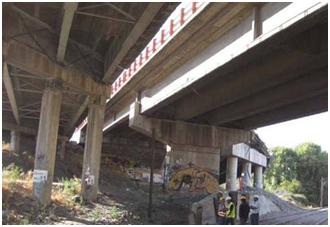
Figure 102. Photo. Three bridges (one demolished) at Route 5 overcrossing at Hospital.
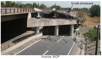
Figure 103. Photo. Collapse of bridge at Route 5 overcrossing at Hospital.
As shown in figure 102, plastic hinges appear to have developed at the top of the columns of the steel plate girder bridge with cross frames and shear keys. The fact that hinges formed at the top of the columns implies that strong shaking occurred transversely (i.e., in the direction of the skew). This is one of the few bridges for which column damage was observed, but field data is minimal because the bridge was demolished for safety reasons soon after the main shock. The
only bridge to remain standing at this site after the earthquake had diaphragms but no skew.
The collapsed concrete bridge was a two-span structure skewed approximately 40 degrees. The superstructure comprised four precast girders but no diaphragms. The intermediate bent comprised three columns that rested on drilled shafts. At the bent and two abutments, the bridge deck was vertically tied to the substructure by seismic bars between pairs of adjacent girders. As shown in figure 103, the south span partially fell from the south abutment. The north span was completely unseated. The superstructure appeared to have rotated clockwise away from the acute corner, an observation confirmed after the bridge deck had been removed (see figure 104 and figure 105).
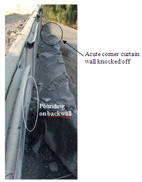
Figure 104. Photo. Damage at north abutment of Route 5 overcrossing at Hospital.
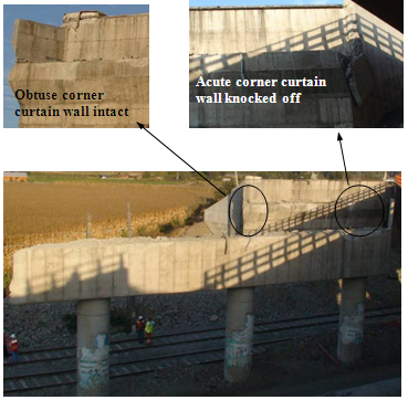
Figure 105. Photo. Damage at south abutment of Route 5 overcrossing at Hospital.
4.3.5 Quilicura Railway Overcrossing at Avenida Manuel Antonio Matta
The Quilicura railway overcrossing at the Avenida Manuel Antonio Matta, located north of Santiago, is a three-span steel bridge with five discontinuous girders, a continuous deck slab,
and seat-type abutments, as shown in figure 106. The abutments and two intermediate piers are skewed approximately 45 degrees. Steel diaphragms are provided at each support, and cross frames and stiffeners are evenly spaced along the spans, as shown in figure 107 and figure 108. The intermediate piers have five circular columns and a bent cap where the simply supported girders are anchored.
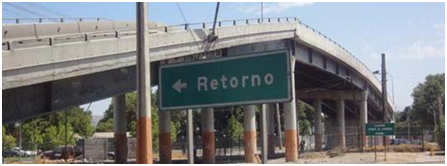
Figure 106. Photo. Overview of Quilicura railway overcrossing.
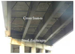
Figure 107. Photo. Cross frames on Quilicura railway overcrossing.
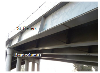
Figure 108. Photo. Stiffeners on Quilicura railway overcrossing.
During the earthquake, the superstructure moved both longitudinally and transversely and rotated away from the acute corner of the bridge. The end span on the east side was unseated at the abutment (see figure 109), and the span on the west side was laterally displaced and almost unseated (see figure 110). For safety reasons, this span was lifted off the abutment about a day after the main shock and was lowered onto a bank of sand placed under the bridge, as shown in figure 111.
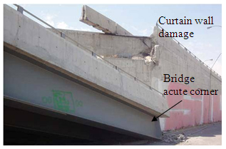
Figure 109. Photo. East abutment of Quilicura railway overcrossing.
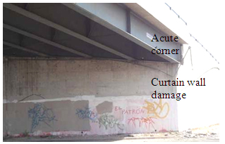
Figure 110. Photo. West abutment of Quilicura railway overcrossing.
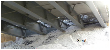
Figure 111. Photo. West span of Quilicura railway overcrossing lowered onto sandbank.
Due to the transverse displacement and rotation of the superstructure, the curtain walls at the acute corners of the bridge sustained pounding damage. In addition, the lateral forces on the superstructure damaged the girder anchor bolts and buckled some cross frames, as shown in figure 112 and figure 113.
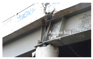
Figure 112. Photo. Damage to anchor bolts on Quilicura railway overcrossing.
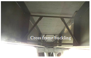
Figure 113. Photo. Damage to cross frame on Quilicura railway overcrossing.
4.4 PERFORMANCE OF STEEL BRIDGES
4.4.1 Tubul Bridge
The Tubul bridge is an eight-span simply supported steel girder bridge oriented north-south with a span length of approximately 92 ft (28 m). Each span consists of three steel girders with concrete end diaphragms, as shown in figure 114. Shown in the inset of figure 114 are four seismic bars between the end diaphragm and the wall pier. The bridge is most likely supported on pile foundations. All the spans were unseated at their south end, resulting in the northern-most span punching into the north abutment and in the buckling of nearby pavement, as shown in figure 115 and figure 116. With the exception of span 6, all the spans were in general alignment in the north-south direction.
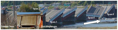
Figure 114. Photo. Unseating at southern ends of each span of Tubul bridge.
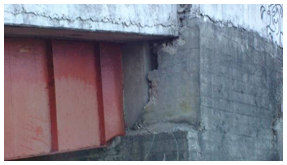
Figure 115. Photo. Punching of Tubul bridge deck into back wall.
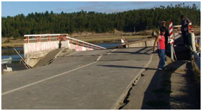
Figure 116. Photo. Buckling of pavement at north abutment of Tubul bridge.
Local damage to the various piers and spans was inspected by boat. As shown in figure 114, span 6 lost support at its north end. Local residents confirmed that this span was like the others immediately after the main shock, but the north end collapsed during an aftershock during the first week, probably due to rigid body rotation of the wall pier. This difference in span 6 may be attributable to the fact that the span rotated from the north to the northeast, creating load concentration on the north support. Figure 117 shows watermarks on one of the wall piers. The concrete below the high watermark showed signs of deterioration, probably due to wet and dry cycles, particularly in the mid-height of the wet area at the average watermark.
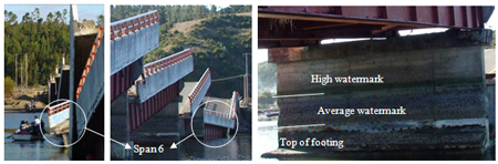
Figure 117. Photo. Span 6 of Tubul bridge, unseated at north end during an aftershock.
In general, the bottom flange of the girders buckled, as shown in figure 115 and figure 118, and the tops of the wall piers were damaged locally, as shown in figure 118 and figure 119. All of the piers were tilted toward the north abutment and were significantly damaged either by flexural effects at the top of the footing due to the maximum moment as the bridge deck pushed against the wall during the earthquake or by shear effects around the average watermark where the concrete was severely deteriorated (see figure 119 and figure 120). Concrete spalling associated with both a shear crack and a vertical crack on the wall pier are shown in figure 121. The pile cap holding the dropped span was cracked, as shown in figure 122, probably due to the impact of the falling span.
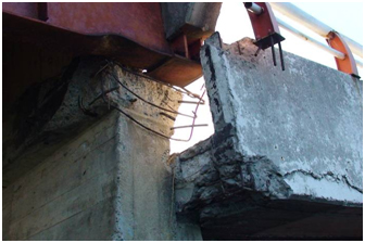
Figure 118. Photo. Bottom flange buckling and concrete spalling on Tubul bridge.
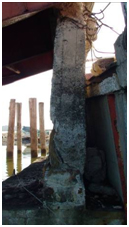
Figure 119. Photo. Shear crack in Tubul bridge.
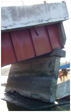
Figure 120. Photo. Tilting wall pier on Tubul bridge.
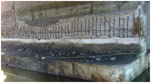
Figure 121. Photo. Spalling due to shear action and vertical crack in Tubul bridge.
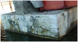
Figure 122. Photo. Crack in footing of Tubul bridge.
4.4.2 Cardenal Raúl Silva Henríquez Bridge
The Cardenal Raúl Silva Henríquez bridge, built in 2002, is a 22-span steel girder structure that crosses the Maule River in the northeast-southwest direction near Constitución. It is supported by 2 seat-type abutments and 21 intermediate bents (see figure 123). The first five bents from the northeast abutment are supported on two reinforced concrete columns and drilled shafts. The next six bents are supported on three reinforced concrete columns and drilled shafts. The following eight bents are steel pile bents with three legs (one vertical and two inclined) and horizontal struts and diagonal braces interconnecting the legs in each bent. The last two bents are supported on three reinforced concrete columns that rest on footings. The superstructure comprises two continuous segments of 11 spans each. There are fixed joints at each abutment and an expansion joint at the middle of the bridge over bent 11. Note that girders with fixed bearings at an abutment seem to defeat the purpose of having expansion joints at the abutment. At each abutment, the bottom flanges of the three girders are welded to masonry plates embedded in the abutment seat. An elastomeric pad is provided over each intermediate bent to permit longitudinal movement. Transverse and vertical movements are restrained by steel stoppers, as shown in figure 124.
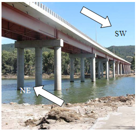
Figure 123. Photo. Cardenal Raúl Silva Henríquez bridge looking south.
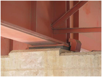
Figure 124. Photo. Elastomeric pad and stopper over bent
on Cardenal Raúl Silva Henríquez bridge.
During the earthquake, the northeast portion of the bridge moved from west to east in the transverse direction. All steel stoppers were deformed, and girders were displaced from their elastomeric pads. The transverse diaphragms at the intermediate bents and abutments buckled, as shown in figure 125 and figure 126. At the northeast abutment, the webs and bottom flanges were fractured in all three steel girders, and both bearing stiffener and web buckling occurred, as shown in figure 127. The exterior girder also experienced web and flange bending about its weak axis, as shown in figure 128. Web buckling was observed in the longitudinal direction in the same girder. This type of damage is evidence of large longitudinal loads in the superstructure being attracted to the fixed bearing at this abutment and that these loads changed sign from tension to compression several times during the long-duration event. The weld between the girders and the masonry plate did not fail.
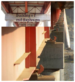
Figure 125. Photo. Elastomeric pad and stopper over bent
on Cardenal Raúl Silva Henríquez bridge.
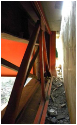
Figure 126. Photo. Elastomeric pad and stopper over bent
on Cardenal Raúl Silva Henríquez bridge.
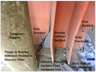
Figure 127. Photo. Elastomeric pad and stopper over bent
on Cardenal Raúl Silva Henríquez bridge.
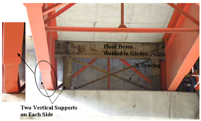
Figure 128. Photo. Elastomeric pad and stopper over bent
on Cardenal Raúl Silva Henríquez bridge.
To maintain traffic on the bridge, a temporary cross frame was installed at the northeast abutment, as shown in figure 128. Due to severe damage in the girder webs and flanges, a steel beam was used to transfer loads from the girder flanges to the abutment seat, bypassing the webs.
As previously noted, nine spans of the southwest portion of the bridge are supported on tall steel pile bents, as shown in figure 129. The legs of these bents are fabricated from 4.9-ft (1.5-m)-diameter tubes with a wall thickness of 0.55 inches (14 mm). Their overall heights from pile tip to soffit range from 146 to 169 ft (44.5 to 51.5 m). The maximum clear height above water is about 82 ft (25 m). This portion of the structure appeared to have performed well during the earthquake but suffered local damage at several locations due to tsunamis. Four major waves were recorded nearby, with arrival times ranging from 4 to 5.5 h after the earthquake. Wave heights ranged from 22.6 to 36.7 ft (6.9 to 11.2 m), passing under the superstructure. Nevertheless, the waves eroded river sands and gravels from around the piles to a depth of about 15 ft (4.5 m), and waveborne debris punctured a hole in the wall of one of the legs of one of the bents (see figure 130 and figure 131).
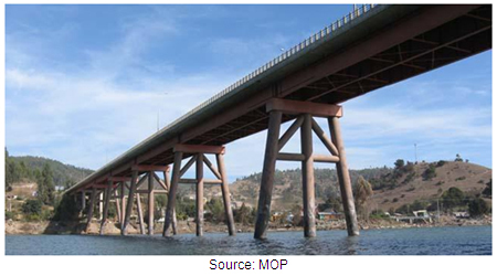
Figure 129. Photo. Elastomeric pad and stopper over bent
on Cardenal Raúl Silva Henríquez bridge.
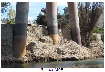
Figure 130. Photo. Elastomeric pad and stopper over bent
on Cardenal Raúl Silva Henríquez bridge.
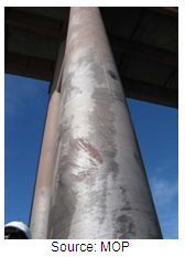
Figure 131. Photo. Elastomeric pad and stopper over bent
on Cardenal Raúl Silva Henríquez bridge.
Although the details are similar, the damage to the girders at the southwest abutment was not as severe as at the northeast abutment and was limited to the buckling of the bearing stiffeners. The reason for this difference is probably that the fillet welds connecting the girder flanges and bearing stiffeners to the masonry plates failed during the earthquake and large longitudinal loads were not attracted to this abutment (see figure 132 through figure 134).
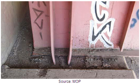
Figure 132. Photo. Elastomeric pad and stopper over bent
on Cardenal Raúl Silva Henríquez bridge.
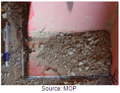
Figure 133. Photo. Close-up of girder end on Cardenal Raúl Silva Henríquez bridge.
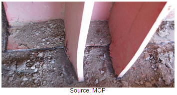
Figure 134. Photo. Close-up of transverse stiffeners on Cardenal Raúl Silva Henríquez bridge.
4.4.3 Biobío River Bridge
The first bridge over the Biobío River in Concepción was built in 1925 and consisted of 108 simply supported spans of approximately 49 ft (15 m) each. Each span had a timber superstructure (beams and deck) and rested on concrete piers that were supported on battered timber piles. After 40 years of service, the Chilean Highway Authority decided to replace the bridge with a steel-girder structure of 90 spans (approximately 49 ft (15 m) each), which were also supported on wall piers and timber pile foundations. During the 1960 earthquake, the five spans closest to Concepción collapsed. In 1965, an additional three spans collapsed due to scour effects. As a result, most of the pile foundations were replaced in the mid-1960s with steel pipe piles and concrete cap beams. In 1994, Japanese consultants evaluated the structural integrity of the bridge and investigated various retrofitting options. It was concluded that the bridge should be closed to traffic and was too expensive to retrofit due to the deterioration of many structural components. Nevertheless, local authorities decided to keep the bridge open for limited traffic such as pedestrians and bicycles. After additional studies, the bridge was completely closed in 2002, and all traffic was detoured to the Llacolen bridge, which had been built in 2000. In 2009, MOP contracted the firm Q&R Ingeniería to conduct a preliminary study for the replacement of the Biobío bridge.
The historic multispan bridge over the Biobío River is oriented approximately east-west. As seen in figure 135 and figure 136, the bridge superstructure consists of multiple simply supported spans with four steel girders and a concrete deck. Intermediate and end X-braced cross frames were provided in each span. Each end of a steel girder was restrained by two anchor bolts through the bottom flange, one on either side of the web. As shown in figure 137, lateral spreading due to liquefaction was observed near the north end of the bridge approaches. Many spans moved longitudinally and fell from their seats after shear failure of the anchor bolts. Some piers also collapsed in the longitudinal direction, as shown in figure 138, possibly due to liquefaction-induced vertical settlement in combination with longitudinal seismic forces. These movements may have caused the multiple cracks visible in the pile caps (see figure 139).
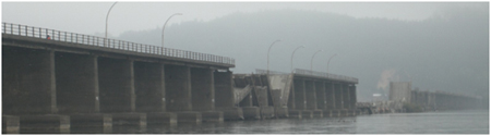
Figure 135. Photo. Collapsed spans in Biobío River bridge.
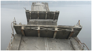
Figure 136. Photo. Unseated spans in Biobío River bridge.
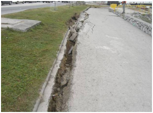
Figure 137. Photo. Lateral spreading near east end of Biobío River bridge.
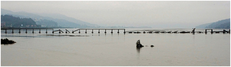
Figure 138. Photo. Collapsed spans and piers of Biobío River bridge.
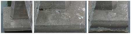
Figure 139. Photo. Cracks in pile caps of Biobío River bridge.
4.4.4 Pichibudis Bridge
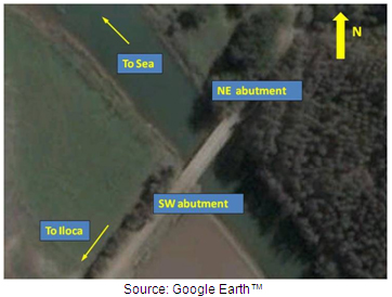
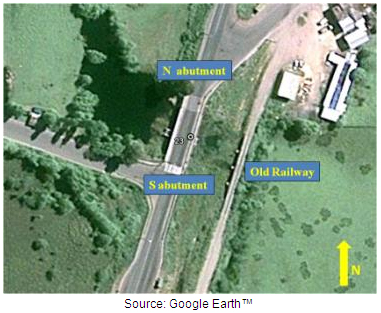
The Pichibudis bridge is located on a coastal road (Route J-60) in Punta Duao near Iloca. The bridge crosses a stream 980 ft (300 m) before the stream flows into the sea (see figure 140).
© Google, DigitalGlobe, Inav/Geosistemas SRL, and DMapas
Figure 140. Photo. Satellite image of Pichibudis bridge.
The single-span bridge has a total length of approximately 98 ft (30 m). The superstructure is composed of two parallel 62-inch (1,600-mm)-tall plate girders and a reinforced concrete deck slab. The girders are detailed with cross frames and stiffeners evenly spaced along the span, as shown in figure 141 and figure 142. The supports are seat-type abutments, reinforced concrete diaphragms, and concentric braces fabricated from steel reinforcing bars. The bottom flange of each girder sits on rubber pads at each abutment.
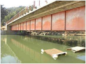
Figure 141. Photo. Cross frames in Pichibudis bridge.
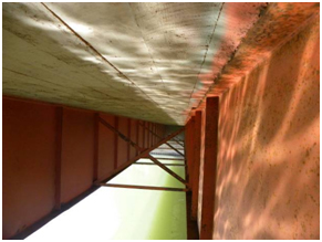
Figure 142. Photo. Web stiffeners in Pichibudis bridge.
The bridge was overtopped by one or more tsunami waves, and the deck slab suffered a permanent lateral displacement of about 7 inches (180 mm) at the south abutment (see figure 143 and figure 144). At this abutment, the seaward girder rotated about the bottom flange and suffered flexural and torsional deformations about the weak axis of the section.
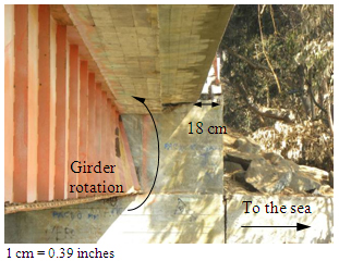
Figure 143. Photo. Offset in girder top flange of south abutment of Pichibudis bridge.
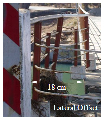
Figure 144. Photo. Offset in handrail on south abutment of Pichibudis bridge.
At the same location, damage was also found in the concrete diaphragm and bracing system, with tension rupture in one bar and compression buckling in the other one (see figure 145 and figure 146).
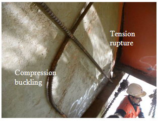
Figure 145. Photo. X-braces damage in south abutment of Pichibudis bridge.
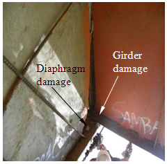
Figure 146. Photo. Diaphragm crushing in south abutment of Pichibudis bridge.
According to local residents, the tsunami was characterized by three waves starting approximately 10 min after the main shock. Since the clear height of the bridge from the water level is about 4.9 ft (1.5 m), the tsunami waves passed over the bridge, inducing large lateral forces on the girders. In addition, a visual inspection of the connecting elements at the south abutment revealed corrosion in the girders, cross braces, and vertical restrainers in the reinforced concrete diaphragms (see figure 147). Due to the corrosion, the capacity of the structural components of the south abutment was less than at the north abutment, making this abutment more likely to suffer damage.
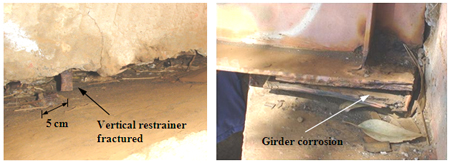
Figure 147. Photo. Damage on south abutment due to corrosion in Pichibudis bridge.
4.4.5 El Bar Bridge
The El Bar bridge is located on Route 160 in Arauco and crosses a small lake in the province of Carampangue, as shown in figure 148.
© Google, GeoEye, and DMapas
Figure 148. Photo. Satellite image of El Bar bridge.
Originally designed as a single-span bridge with a total length of approximately 98 ft (30 m), an intermediate support had recently been added (see figure 149). Apparently, this bridge suffered structural damage during flooding in 2006 and was retrofitted accordingly. In addition to the midspan support frame, two new plate girders were added parallel and adjacent to the existing girders. The new girders were connected to the existing girders using welded steel angles, as shown in figure 150. The connection between the new beams and the deck slab was made using steel angles and bolts anchored with epoxy, as shown in figure 151.
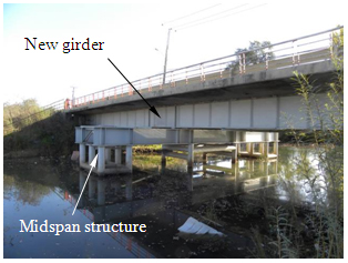
Figure 149. Photo. Satellite image of El Bar bridge.
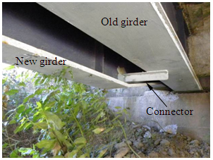
Figure 150. Photo. Satellite image of El Bar bridge.
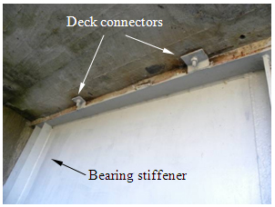
Figure 151. Photo. Satellite image of El Bar bridge.
Earthquake damage at the south abutment included a lateral permanent deformation of 9.8 inches (250 mm), girders dislodged from their neoprene pads, and damage to the concrete back wall (see figure 152 and figure 153). When the bridge was retrofitted after the 2006 floods, a rebar X brace system and a new concrete diaphragm were added at the north abutment. The diaphragm was anchored to the abutment seat using vertical restraining bars (seismic bars). Earthquake damage observed at this support included large deformations in the rebar of the X-brace system (tension yielding and compression buckling), lateral deformation of the seismic restrainers, and concrete crushing of the original abutment back wall (see figure 154 and figure 155).
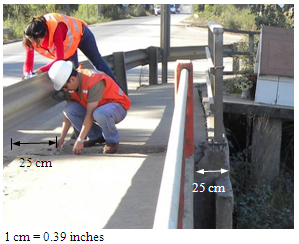
Figure 152. Photo. Lateral deformation at south abutment of El Bar bridge.
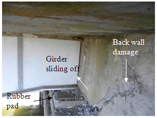
Figure 153. Photo. Damage at south abutment of El Bar bridge.
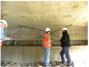
Figure 154. Photo. Damage to rebar X-brace system on north abutment of El Bar bridge.
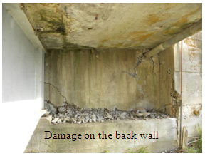
Figure 155. Photo. Damage to north abutment back wall of El Bar bridge.
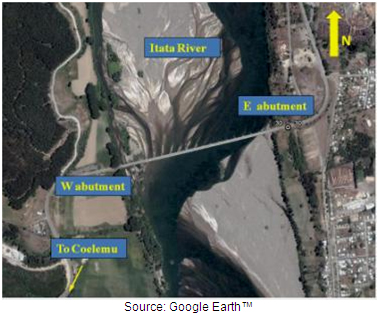
4.4.6 Itata River Bridge
Built in 1980s, the Itata River bridge crosses the river near Coelemu (see figure 156). The total length of the bridge is approximately 2,160 ft (660 m) made up of 22 98-ft (30-m) spans. The superstructure is composed of two parallel steel plate girders simply supported between piers and a reinforced concrete deck slab. The substructures include two seat-type abutments and 21 intermediate 39-ft (12-m)-tall wall-type piers (see figure 157). The two girders have equally spaced web stiffeners and are interconnected by inverted chevron-type cross frames. Reinforced concrete diaphragms are provided at the abutments and over each pier.
© Google, DMapas, DigitalGlobe, Inav/Geosistemas SRL
Figure 156. Photo. Satellite image of El Bar bridge.
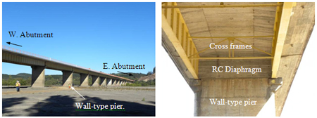
Figure 157. Photo. Side view and superstructure details for Itata River bridge.
Each girder sits on a reinforced concrete bracket at the top of each pier (see figure 158). These brackets were designed to transfer the axial and lateral forces to the piers, which are founded on rectangular pile caps.
During the earthquake, the entire structure moved both longitudinally and transversely, with larger displacements occurring in the transverse direction. As a consequence, many of the concrete brackets suffered damage at their connections to the piers. The damage was characterized by shear cracks, concrete spalling, and bar buckling, as shown in figure 159. At the time of inspection, a temporary steel structure was under construction to retrofit the brackets and allow traffic on the bridge.
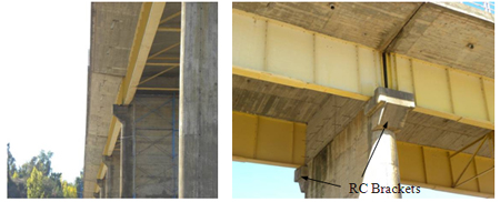
Figure 158. Photo. Girder supports at each pier of Itata River bridge.
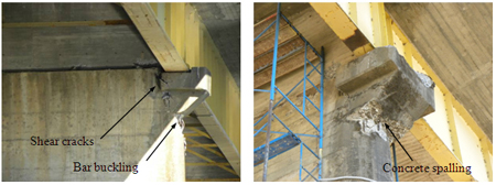
Figure 159. Photo. Damage to girder supports of Itata River bridge.
4.4.7 Pedestrian Bridge Over Route 5
Several pedestrian bridges over Route 5 collapsed during the earthquake. All appeared to have similar details and to have failed in a similar manner. The collapse of the pedestrian bridge at KM 13.8 of Route 5 North is described in this section. The bridge consisted of two approach ramps on each side of the highway and a two-span overpass oriented approximately east-west. As shown in figure 160, the two spans fell from their supports during the earthquake and were subsequently moved to the sides of the highway. Each 70.1-ft (21.4-m)-long span consisted of a concrete deck supported by two steel plate girders and four uniformly spaced cross frames. The end of each girder rested on a neoprene pad, as shown in figure 161. Each cross frame was composed of X bracing, a top chord, and a bottom chord, as shown in figure 162. The main span was anchored at each end to a hammerhead pier by two 1-inch (25-mm)-diameter bolts through the flange of the bottom chord. Failure occurred when the anchor bolts pulled out of the bottom chord and there was insufficient seat width to prevent the girders from collapsing (see figure 163).
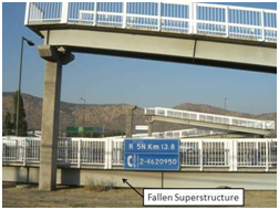
Figure 160. Photo. Damage to girder supports of Itata River bridge.
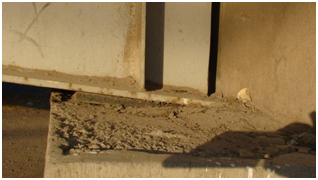
Figure 161. Photo. Damage to girder supports of Itata River bridge.
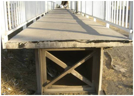
Figure 162. Photo. Damage to girder supports of Itata River bridge.
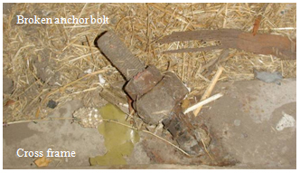
Figure 163. Photo. Damage to girder supports of Itata River bridge.
4.5 PERFORMANCE OF OTHER BRIDGE TYPES
4.5.1 Claro River Bridges
Three arch bridges cross the Claro River just south of Curicó. Two of these are shown in figure 164: a reinforced concrete highway arch that carries northbound and southbound lanes of Route 5 and a set of unreinforced masonry arches. Built in 1870, the masonry bridge is a historic structure. It has survived numerous strong earthquakes in its lifetime, including the 1960 and 1985 events. The reinforced concrete arch suffered only minor damage during the 2010 earthquake, but the masonry bridge collapsed completely (see figure 165).
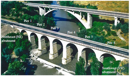
Figure 164. Illustration. Highway bridges crossing Claro River before earthquake.
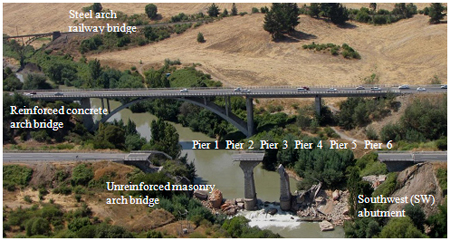
Figure 165. Photo. Collapse of masonry arch bridge at Claro River.
The masonry bridge consisted of a set of seven back-to-back arches oriented approximately northeast-southwest. Two piers survived the earthquake, and all foundations appeared to be intact, as shown in figure 165 and figure 166.
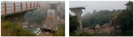
Figure 166. Photo. Close-up view of collapsed bridge at Claro River.
Figure 167 through figure 169 show details of various components of the bridge. The deck slab was approximately 8 to 10 inches (203 to 254 mm) thick, and the arch crown was approximately 4 ft (1.2 m) thick. The ribs and piers were constructed from solid brick with some stone fill above the brick ribs, as shown in figure 167 and figure 168, and faced with stone blocks or plastered with cement to give the appearance of stonework. Close inspection of the piers found some cracks between the bricks and stone facades, possibly due to shaking, but, in general, the masonry was in excellent condition. The foundations of the bridge were most likely made of stone blocks and seemed to have experienced little or no damage during the earthquake (see figure 169).
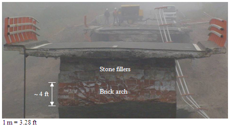
Figure 167. Photo. Deck slab and crown of arch on Claro River bridge.
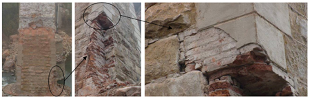
Figure 168. Photo. Pier of Claro River bridge.
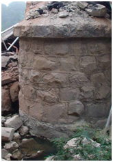
Figure 169. Photo. Foundation of Claro River bridge.
As shown in figure 166, the collapsed spans and other debris, including arches and piers, fell directly into the river below the bridge and were not thrown sideways, upstream, or downstream. Therefore, one scenario is that the collapse was caused by the failure of a pier with deteriorated masonry during strong shaking along the axis of the bridge. Another scenario is that the elevation difference between the end support of the arch bridge and its nearby pier caused stress concentration in two end spans along the axis of the bridge, resulting in cracks in the ribs and falling of various pieces. The collapse of two end spans reduced the inward thrust of each intermediate arch span and triggered progressive collapse. Since no deterioration of the masonry was observed in the rubble in the river bed, the second scenario is most likely.
Based on field observations, the progressive collapse of the entire masonry bridge could have occurred in four steps, as shown in figure 170. The figure shows the pre-earthquake condition of the bridge, indicating the horizontal inward thrust of each arch under gravity loads. Due to the difference in support conditions in the two end spans, the bending moment distribution along the axis of the arch bridge was quite uneven under the earthquake load. The maximum moment most likely occurred in the end spans. As a result, each end arch was subjected to cracking, leading to loss of various pieces (see step 1 of figure 170). As the end spans collapsed, the sudden loss of thrust for the adjacent spans caused significant force redistribution in a short time, resulting in cracking and collapse of the spans under gravity or earthquake loads, as illustrated in step 2. Similarly, the next spans collapsed, as shown in step 3.
Next, the center span experienced force redistribution due to the collapse of its adjacent spans. However, the change in horizontal thrust for the center span was likely smaller than that in the other intermediate spans. In addition, the earthquake excitation was likely over by that time. Therefore, the arch collapsed mainly due to its own weight while the two piers supporting the center span remained, as shown in step 4. When compared with figure 165, this collapse matches the field observations.
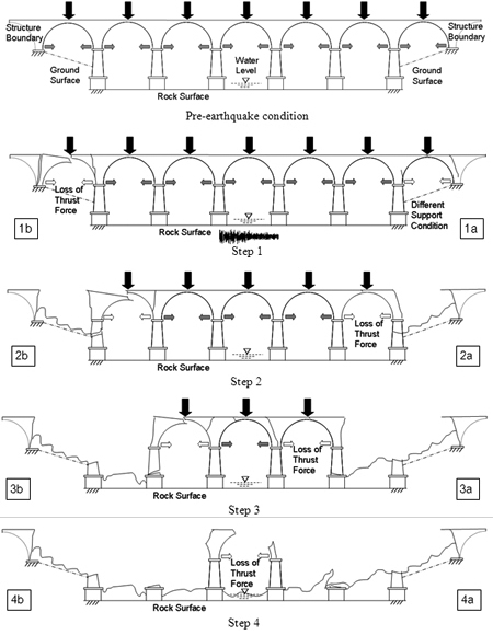
Figure 170. Illustration. Scenario for the progressive collapse of Claro River bridge.
4.5.2 Chepe Railroad Bridge Over Biobío River
The Chepe railroad truss bridge over the Biobío River was built in 1889 and retrofitted in 2005. Oriented northeast-southwest, the bridge has two continuous through-truss spans at the north end and multiple truss spans for the river crossing (see figure 171 through figure 173). The through-truss structure is supported on the north abutment and two intermediate bents. Each bent comprises two concrete-filled steel tubes that are 72 inches (1,807 mm) in diameter, as shown in figure 174. All the river spans are supported on steel towers. Each tower comprises six steel circular piles that are cross-braced for lateral strength and stiffness (see figure 172 and figure 175). A view underneath the through-truss spans and a sectional view of the remaining spans are shown in figure 174 and figure 175.
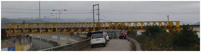
Figure 171. Photo. North end of Chepe railroad bridge over roadway.
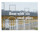
Figure 172. Photo. River spans of Chepe railroad bridge.
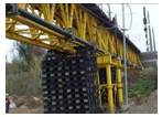
Figure 173. Photo. South end of Chepe railroad bridge.
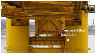
Figure 174. Photo. Bottom view and cross section on north end of Chepe railroad bridge.
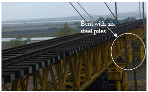
Figure 175. Photo. Section on south end of Chepe railroad bridge.
At the northeast end, the bridge spans over Route O-60, which runs in a trench between two retaining walls, as shown in figure 176. The roadway slab is supported by micropiles that are approximately 20 ft (6.1 m) long. During the earthquake, the steel tube bent behind the river-side retaining wall settled approximately 12 inches (300 mm) and moved laterally toward the river for approximately 26 inches (660 m). It also tilted toward the river about 5 degrees, as shown in figure 177. In the vicinity of the steel tube bent, the soils behind the wall settled approximately 51 inches (1,300 mm) relative to the steel bent, as shown in figure 177. The retaining wall settled over 12 inches (300 mm), as shown in figure 178, and moved laterally toward the river for approximately 26 inches (660 mm), as shown in figure 176. As a result, the seal between the roadway and toe of the retaining wall sustained damage, creating the possibility for water to flood the roadway as the river level rises during the winter. The movement of the steel tubes and retaining wall was due to liquefaction-induced ground spreading.
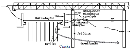
Figure 176. Illustration. Settlement and lateral movement of wall and bent due to ground spreading under Chepe railroad bridge.
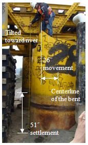
Figure 177. Photo. Settlement and tilting of bent on Chepe railroad bridge.
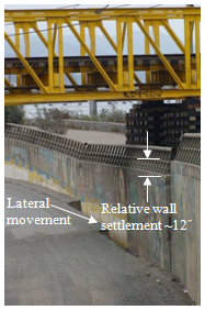
Figure 178. Photo. Settlement behind retaining wall on Chepe railroad bridge.
At the south end of the bridge, several bracing rods were broken, and at least two steel piles were fractured, possibly due to ground spreading, as shown in figure 179 and figure 180. A temporary support comprising a stack of timber ties had been erected near the damaged bent, as shown in figure 173.
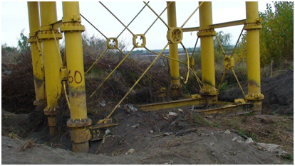
Figure 179. Photo. Ruptured cross bracing at south end of Chepe railroad bridge.
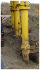
Figure 180. Photo. Fractured steel piles at south end of Chepe railroad bridge.
4.5.3 Maipú River Bridges4.5.3 Maipú River Bridges
Three bridges cross the Maipú River just south of Santiago: a railway bridge, a highway bridge (Route 5), and a local access road bridge (see figure 181).
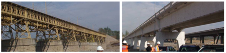
Figure 181. Photo. Three parallel bridges crossing Maipú River south of Santiago.
The railway bridge seemed to be undamaged by the earthquake. Likewise, the Route 5 bridge sustained only minor damage despite being built in 1970. However, the Route 5 bridge is susceptible to scour, and the foundations were being retrofitted at the time of the reconnaissance visit. The local access road bridge was severely damaged in the earthquake.
Built in 1960s, the Maipú River bridge has four continuous segments of 3, 3, 3 and 4 spans, for a total of 13 spans. The segments are separated by expansion joints. Each reinforced concrete span is composed of three girders with end haunches, six intermediate diaphragms, and two end diaphragms. The superstructure is supported by A-shaped reinforced concrete piers, as shown in figure 181.
Oriented approximately north-south, the bridge was used to carry trucks loaded with gravel dredged from the river. Field observations indicated the existence of shear cracks near the ends of many of the girders, probably caused by heavy truck loading (see figure 182 and figure 183). Some of these cracks appeared to have been repaired prior to the earthquake.
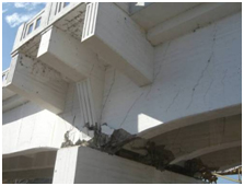
Figure 182. Photo. Crushing of haunches at pier 3 of Maipú River bridge.
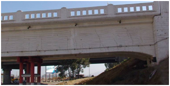
Figure 183. Photo. Shear cracks at span 1 of Maipú River bridge.
During the earthquake, the haunches of three girders over pier 3 were severely crushed, as shown in figure 182. Some concrete diaphragms, such as those at piers 2 and 3, were also cracked significantly, as shown in figure 184. After the earthquake, two temporary frames were installed underneath span 1, and lightweight traffic was permitted on the bridge. Most likely, the crushing of the girder haunches was mainly due to a combined effect of seismic-induced longitudinal shear force and vertical load, as shown in figure 184.
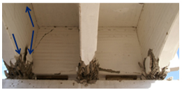
Figure 184. Photo. Longitudinal and vertical seismic forces in haunches at pier 3 of Maipú River bridge.
|


