U.S. Department of Transportation
Federal Highway Administration
1200 New Jersey Avenue, SE
Washington, DC 20590
202-366-4000
Federal Highway Administration Research and Technology
Coordinating, Developing, and Delivering Highway Transportation Innovations
 |
| This report is an archived publication and may contain dated technical, contact, and link information |
|
Publication Number: FHWA-RD-99-194
Date: June 2000 |
|||||||||||||||||||||||||||||||||||||||||||||||||||||||||||||||||||||||||||||||||||||||||||||||||||||||||||||||||||||||||||||||||||||||||||||||
Development and Field Testing of Multiple Deployment Model Pile (MDMP)CHAPTER 2. MODEL PILES FOR FIELD TESTING - REVIEW2.1 Definition and OverviewA model pile is a calibrated tool equipped with instrumentation capable of monitoring the pile/soil interaction over the pile history. Monitoring includes the installation, pore pressure dissipation combined with consolidation and soil pressure equalization, and ultimately, the pile behavior under loading up to failure. The model pile installation and soil-structure interaction simulate the actual field conditions of full-scale piles in a better way than any other possible laboratory or in situ testing. As such, the obtained information can be utilized directly (e.g., skin friction) or extrapolated (e.g., pore pressure dissipation time) to predict the soil's response during full-scale pile installation. Model piles utilize multiple electronic sensors, including, but not limited to, load cells, pressure transducers, total stress cells, accelerometers, and displacement transducers. These sensors can measure pile stresses, pore pressures, radial soil stresses, accelerations, and displacements. The data collected from the model pile can be used to determine load transfer, pile forces, soil friction values, and time-dependent capacity. Limited numbers of model piles have been developed and their use is not common in daily practice. This view excludes the cone penetration test (CPT) that partially fulfills the "model pile" concept, though it was developed and widely used for the determination of soil parameters and site investigation. The available model piles consist of different geometries and are used for different purposes. Some model piles simulate open- and closed-ended pipe piles by varying the tip configurations. Other model piles have been used for cyclic loading simulating the conditions experienced by piles for offshore structures under wave action. Many technical details are associated with the use and implementation of model piles. Their installation can vary between jacking and driving. While jacking advances the model pile at a constant rate of penetration (pseudo-static), driving is a quick dynamic process similar to the most common full-scale pile installation. The average rate in both cases can, however, be very similar (Paikowsky et al., 1989). Drill rods are usually used to advance the model pile. Their limited length requires frequent interruption of the installation process. This arrangement is different from that associated with common pile installation in two ways: (1) it affects the pore pressure dissipation process and (2) the stress wave propagation during driving is affected by the drill rod connections and variable cross-sections. Pore water pressure measurements are an important aspect of model piles, especially if the effective stress theory is used as the basis for the pile/soil model. Porous stones are used to separate the water in contact with the pressure transducer from the soil and maintain saturation prior to installation. To record accurate pore pressures, the geometry of the porous stones should conform with the model pile shaft, and the porous stone material needs to ensure fast response time of the pressure transducers. The permeability of the porous stone has to be properly balanced between very high permeability that allows a quick response time and low permeability to maintain saturation when the model pile is exposed to air and/or advancing through unsaturated soil. The porous stones and the measuring system need to be properly de-aired since air may fill some of the voids, resulting in decreased permeability and a slower response time. In addition, air can penetrate the duct pipes connecting the pressure transducers and thus affect the accuracy of the measurement. The following sections review model piles that have been previously developed. These model piles were designed for use in the field and to test the in situ pile/soil interaction. There are other types of pile models (usually small in size) that are used in 1-g laboratory pressure chamber and centrifuge testing (Kurup, 1993). These model piles are not discussed in this chapter as their size, type of instrumentation, and conditions of testing differ substantially from that of the field model piles. Table 1 presents a summary of the reviewed model piles following a literature search performed by Peter J. Connors as presented by Ravindra Mynampaty in his Master's Thesis (Mynampaty, 1993). The table was updated with additional literature and with the features of the model pile developed for the current research and presented in Chapter 3. 2.2 The Cone Penetration Test (CPT) ModelThe cone penetrometer has been used to identify soil type, stratigraphy, and variability for more than 60 years. The cone penetrometer has evolved from an original mechanical cone to an electric cone and a piezocone that are currently used for in situ testing (see Figure 1). Electric cones are capable of continuously monitoring tip resistance and skin resistance. When equipped with a piezometric element, they can monitor pore pressure (DeRuiter, 1982; Schaap and Zuiberg, 1982; and Chen and Mayne, 1994). The cone penetrometer has been standardized throughout the many years of use. The ASTM Standard Test Method for Deep, Quasi-Static, Cone, and Friction-Cone Penetration Tests of Soil (ASTM D 3441-86) states that the standard cone has a 60º point angle and a base diameter of 35.7 mm (1.406 in) resulting in a projected area of 10 cm2 (1.55 in2). The standard friction sleeve has the same diameter as the cone and has a surface area of 150 cm2 (23.2 in2). Non-standard cones have been developed with projected areas varying from 5 to 15 cm2 as well as different size friction sleeves. The instrumentation of the penetrometer consists of one or more axial load cells and, often, pore pressure transducers. All cone penetrometers have a load cell to measure the resistance at the tip, while new versions that are capable of measuring skin friction have an additional load measurement. A common method to measure skin resistance is the subtraction method, which requires an additional axial load cell that measures the combined load at the tip and friction sleeve. The skin resistance is then determined by subtracting the tip resistance as measured by the axial load cell at the tip from the combined resistance as measured by the axial load cell located in the shaft. Pore pressure measurements are measured with pressure transducers mounted in the tool.
Figure 1. The Dual Piezo Friction Cone Penetrometer(De Ruiter, 1982). The location of the pore pressure transducer is not yet standardized and is often in one or more of the following locations: at the tip, behind the tip, and/or above the friction sleeve (Figure 2). For an effective tool to investigate pile/soil interaction, pore pressure needs to be measured on the shaft, well above the friction sleeve (Paikowsky et al., 1995). Pore pressure measures at positions u1 and u2 are useful when determining soil stratigraphy. Cone penetrometer with pore pressure measurements are referred to as piezocone penetrometers. Some variations of the cone may include other sensors such as an omni-directional inclinometer (a slope-sensing device), nuclear density probe, and acoustic probe. Nuclear density probes are able to detect changes in density of the soil by emitting and receiving radioactive isotope rays. The inclinometer can detect if the cone penetrates in the vertical direction. This verifies the depth of the model and is useful for the recovery of probes before they deviate too far off course. Figure 2. Typical Locations of Pore Pressure Measurements for Piezocone Penetrometers. The loading system for penetrometers is often contained in a portable vehicle that can be ballasted to provide the full reaction for the testing. The system includes either a hydraulic ram or a hydraulic clamping system to insert the model. The clamping system is very useful because it enables the addition of drilling rods without interrupting the advancement of the model. The cone is advanced at a constant rate of 20 mm/s. Disadvantages that may hinder the ability of the cone to simulate pile installation are: (1) the device requires the use of drill rods to advance the cone into the soil (this delay, caused by the addition of drill rods, enables the soil surrounding the pile to set up and pore pressure to dissipate), (2) the friction sleeve is behind the tip, hence it does not represent typical shaft conditions, and (3) the non-standardized placement of the pore pressure filter along the surface of the cone and/or at its base where the measured pore pressure is not representative of the pile shaft conditions. 2.3 The Piezo-Lateral Stress (PLS) CellThe 38.4-mm- (1.51-in-) diameter Piezo-Lateral Stress Cell (PLS) (see Figure 3) was originally developed by Wissa et al. (1975). The device was introduced in 1978 to provide essential fundamental data on pile behavior in clay in order to expand the knowledge of long piles behavior, especially the skin friction component of long piles total capacity (Azzouz, 1985b; Azzouz and Lutz, 1986; and Azzouz and Morrison, 1988). In addition, the device can be utilized as an exploratory tool to directly estimate the shaft resistance of cylindrical piles (Morrison, 1984). The PLS cell has been used successfully in cohesive soils at three Boston Clay sites and at the Empire, Louisiana clay site. At the Empire site, a direct comparison could be made with full-scale piles that were previously tested at the site. The PLS cell has three components that provide a simultaneous measurement of total lateral stress, pore pressure, and axial load throughout the various stages of the life of the model pile. The total lateral (horizontal) stress and pore pressure measurements are used to determine the horizontal effective stress acting on the pile, a dominant parameter for calculating skin friction when evaluating pile behavior in cohesive soils based on effective shear strength theory. The lateral stress cell is made of a thin steel shell that covers a thin water-filled pressure chamber (Figure 4). The lateral stress experienced by the shell is transferred to the water in the pressure chamber where the water pressure is measured with a pressure transducer. The ideal lateral stress cell would have an infinitely thin, long steel shell with a large diameter and a minute amount of water in the pressure chamber while being insensitive to axial load. The final design incorporated these ideas as well as practical concerns such as durability and machineability. Sensitivity of the lateral stress cell is expressed as a ratio of the internal water pressure to the external horizontal stress. The constructed element has a sensitivity of 93.5%, with the steel shell being 0.038 cm (0.015 in) thick, 4.70 cm (1.85 in) long, diameter of 3.84 cm (1.51 in), and pressure chamber volume of 2.13 cm3 (0.13 in3). The rated range of the lateral stress cell is 0 to 689.5 kPa (0 to 100 psi). The PLS cell also includes a thermoresistor monitoring temperature. This measurement is essential for achieving a high degree of accuracy in horizontal stress readings when using very stiff, temperature-sensitive devices such as the PLS's lateral cell. Improvement of such devices can be made when using liquid in the pressure chamber with an expansion coefficient more compatible to steel than water (for example, mercury). A high-entry, stainless-steel porous disk allows the pore water pressure to be measured by an internal pressure transducer. The rated range of the pore pressure transducers is 0 to 1379 kPa (0 to 200 psi). Improper de-airing of the porous disk causes the system to have a slow response time to externally applied changes in pressure and is a common cause of misleading data. Figure 3. The Piezo-Lateral Stress (PLS) Cell(Morrison, 1984). Figure 4. Detailed Cross-Section of the Piezo-Lateral Stress (PLS) Cell (Morrison, 1984). The load cell measures the axial load required to overcome the tip resistance and shear stresses acting on the length of the shaft bounded by the load cell. Figure 5 provides a detail of the load cell assembly. The PLS has only one axial load cell and utilizes the measurement of tip resistance from an additional piezocone test to determine the skin resistance along the tip extension. The PLS is pushed at a constant rate of 20 mm/s. Like the piezocone and CPT, the data collected with the PLS cell can be analyzed to identify soil stratigraphy. The PLS is comparable in size with AW drill rods; therefore, the cell may be pushed to significant depths without the need for casing the borehole. A disadvantage of the PLS cell is the drilling rods used need to be added at intervals of 1.524 m (5 ft) of advancement. The time needed to add a new rod allows excess pore pressure dissipation, and this must be taken into account when analyzing the pore pressure data. Care must be taken to identify virgin penetration or non-virgin penetration. The non-virgin records are significantly affected by the degree of consolidation. An advantage of the PLS is the ability to vary the length of the tip extension. The length of the tip extension may be changed to minimize the tip effects in a particular soil. This enables a more sensitive measurement of the sleeve resistance and allows the model to simulate the shaft of a long flexible pile. 2.4 The Grosch and Reese (G&R) Model PileThe Grosch and Reese (G&R) model pile (see Figure 6) was developed at the University of Texas for the American Petroleum Institute. The model was developed to provide insight into the mechanics of cyclic reduction in load transfer of long flexible piles utilized for offshore platforms (Grosch and Reese, 1980). The model pile is a 2.54-cm- (1.0-in-) diameter closed-ended tube, 88.9 cm (35 in) in length. The model pile is made of 6061 aluminum and is connected to a 5.08-cm- (2-in-) diameter galvanized pipe to advance the instrumented section to the desired test depth. The G&R model pile measures the load transfer over a 25.4-cm (10-in) section with four strain gauges arranged in a Wheatstone bridge formation. This formation cancels any bending forces and measures only the axial load. A pore pressure transducer was located at the mid-point of the section that measures the load transfer. The instrumentation wires are routed through a flexible hose that was pressurized with 82.7 kPa (12 psi) of nitrogen to prevent moisture from entering the system. The system was designed for simulating cyclic environmental loading often experienced by offshore structures. The loading system consists of a screw jack with a reversible variable-speed motor connected to the model via the 5.08-cm (2-in) galvanized steel pipe. The screw jack enabled the simulation of the environmental loading by cyclic penetration in the bottom of the shallow borehole in a soft, normally consolidated clay deposit in Sabine, Texas. The G&R model pile does not require pre-drilling to insert it to the testing depth. The compactness of the model makes the device relatively mobile.
Figure 5. Details of the Axial Load Cell in the Piezo-Lateral Stress (PLS) Cell(Morrison, 1984).
Figure 6. The Grosch and Reese (G&R) Instrumented Model Pile(Grosch and Reese, 1980). The model pile is not designed to measure tip resistance observed by the pile. It appears that G&R's model would be less accurate than others due to its small surface area, along which load transfer is measured, and its unsophisticated monitoring capabilities. Other model pile designs allow for redundant measurement of skin resistance, while the G&R model pile does not. Also, the drill rods used to advance the model are not compatible with its diameter. This difference in size would require more force to push the model down, a force different from what the model might experience. 2.5 The Norwegian Geotechnical Institute (NGI) Model PileThe Norwegian Geotechnical Institute (NGI) developed a testing instrument to investigate the effects of tension loading on pile anchors used for tension-leg type offshore platforms. The NGI model pile is not capable of measuring tip resistance and, therefore, represents model segments of long flexible piles used in practice. The 15.24-cm- (6-in-) diameter pile is about 5.0 m (16.4 ft) long as shown in Figure 7. The model pile is closed-ended to model large displacement piles (Karlsrud and Haugen, 1981, 1985a, and 1985b).
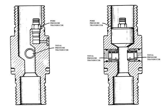
Figure 7. The Norwegian Geotechnical Institute (NGI) Instrumented Test Pile (after Karlsrud and Haugen, 1985). The model pile has six groups of vibrating wire stain gauges distributed at different levels along the length of the pile. These strain gauges are used to determine the skin friction that develops along the pile. The effective stresses can be calculated at four different locations using measurements of earth and pore pressure cells. A displacement transducer and a load cell are positioned on top of the model pile. The instrumentation enables the measurement of the effective stresses and skin resistance during pile installation and consolidation. The NGI model pile has been field tested extensively under a variety of loadings in overconsolidated clay at a site in Haga, outside of Oslo, Norway. Sixteen installations of the model pile were successfully conducted in the overconsolidated clay. An additional section (dummy pile) was attached to the top to advance the model pile to the testing depth. A 6.0-m-diameter concrete ring beam enabled multiple installations of the pile. A jack was used to push the model pile at a rate of 4 to 15 cm/min any place along the ring. Approximately 30 kN (3.37 tons) of force was required to advance the NGI model pile 5 m into the overconsolidated clay. Once inserted, static, rapid, and cyclic loading tests may be performed by a loading rig that travels around the ring beam used for the installations. The disadvantage of the NGI model pile when compared to other similar models is its large diameter and length. As a result, the model pile and its installation and loading rigs cannot be transported easily, making it inappropriate as a standard multiple deployment in situ device. 2.6 The X-Probe And The 3-Inch Model PilesThe Earth Technology Corporation developed two in situ testing tools (the 7.62 cm (3.0 in) and the X-probe) to improve the understanding of axial soil/pile load-transfer behavior for long flexible piles of offshore platforms (Bogard et al., 1985; and Bogard and Matlock, 1990a, 1990b, and 1990c). Both the tools simulate a short pile segment and yield a direct in situ measurement of load transfer along the pile segment. The 7.62-cm (3.0-in) model pile (see Figure 8) has successfully been driven and jacked into a variety of soil types. The X-probe model pile segment tool was designed and built to be used on more routine site investigations. Unfortunately, the X-probe (see Figure 9) did not prove to be rugged enough for repeated testing. The 7.62-cm (3-in) model pile is an in situ testing device with dimensions of 7.62 cm (3 in) diameter and a total tool length of approximately 4.9 m (16 ft). Different cutting shoes, with any wall thickness, can be used to model an open-ended pile, or a closed-ended configuration can be used. Test depths have been as deep as 75 m (250 ft), utilizing N-rods to advance the tool to the desired depth. The 7.62-cm (3-in) model pile is equipped with two load cells that are used to calculate the shear transfer over a section of the pile. Strain gauges (Figure 10) are mounted in a Wheatstone bridge formation to measure only axial loads. In Figure 10, a load cell cover slides over the instrumented section of the load cell to protect the strain gauges and prevent soil and moisture intrusion. Also, mounted in the load cell are two accelerometers (Figure 10). In Figure 11, a total pressure transducer and a pore pressure transducer are located between the two load cells that provide continuous measures of effective stresses at the location where the load transfer is measured. A direct current, linear variable displacement transducer (DC-LVDT) is used to measure local displacement between the cutting shoe and the instrumented portion of the pile. During tension and compression load tests, the cutting shoe acts as an anchor to allow for accurate displacement measurements.
Figure 8 The 7.62-cm (3.0-in) Instrumented Model Pile(Bogard and Matlock, 1985).
Figure 9. The X-Probe(Bogard and Matlock, 1985). The X-probe with a diameter of 4.37 cm (1.72 in) and 143.5 cm (56.5 in) long was designed and built to be used on routine site investigations. The X-probe simulates a plugged pile and has instrumentation that enables the measurement of pile/soil interaction behavior. The pile has a load cell that measures the shear transfer over a 200-cm2 (31-in2) shaft area. Below the load cell are the total lateral pressure transducer and a pore pressure transducer that measure the effective stresses during all stages of pile history. The tip of the pile has a cone with a similar geometry to that of a cone penetrometer. The tip section acts as the reference anchor for local displacement measurements by a displacement transducer. The main advantage of the model is its compatibility with the standard CPT and, therefore, it can be deployed with conventional cone penetrometer equipment. However, the X-probe does not have the capability to measure tip responses. The models have been extensively tested at six onshore sites along the U.S. Gulf coast, West coast, and Canada; a site offshore Louisiana from a fixed platform; and in the laboratory in a pressurized soil drum. The soil types at these locations are composed of stiff silty clay, silts, soft clay, overconsolidated Beaumont clay, and calcareous soil. At some of the sites, full-scale pile static load tests were carried out as well, which enables the comparison of axial behavior between full-scale pile load test results and model pile segment tool results.
Figure 10. Details of 7.62-cm (3-in) Model Pile Axial Load Cells(after Patent Number 5,259,240). The model piles are driven or pushed using N-rods to advance the pile to the desired depth. The instrumentation is monitored during installation and through the duration of the test. Upon the completion of installation and consolidation, a variety of load tests were performed. These loading tests included static monotonic, one-way cyclic (compression or tension only) with or without load bias, and two-way cyclic loading under tension and compression. The loading system consisted of a hydraulic ram, with a 30.48-cm (12-in) stroke, that was able to apply tension or compression loading to the models. Screw anchors are used as a reaction for compressive loadings when testing was conducted onshore. Figure 11. Details of 7.62-cm (3-in) Model Pile Pressure Instruments(after Patent Number 5,259,240). 2.7 The In Situ Model Pile (IMP)The IMP or In Situ Model Pile (see Figure 12) was developed at Oxford University (Coop and Wroth, 1989; and Lehane, 1992) to explore the fundamental behavior of piles in clay. Both stiff overconsolidated and normally consolidated estuarine clays were successfully tested. The model is 80 mm (3.15 in) in diameter and 1135 mm (44.7 in) long. The model pile consists of two concentric cylinders attached to a common pile head, with the inner cylinder rigidly connected to the tip assembly and the outer brass cylinder comprised of a combination of interchangeable instrumented sections. The rigid connection allows for a more sensitive measurement of shaft friction. End bearing forces are transmitted directly to the pile head through the inner cylinder and are not measured. The IMP has two instrumentation clusters, with each section having two pore pressure transducers, two radial stress transducers, and a load cell. There is an additional pore pressure transducer located at the tip of the pile and a third load cell located in the leading cluster. Figure 12 presents the location of the sensors, as well as diagrams of two types of pore pressure sensors and radial stress sensor. The Druck semi-conductor transducer is a brand name pressure transducer that was installed into the IMP while the strain-gauged diaphragm was constructed specifically for the IMP. The three load cells measure axial load, enabling the skin friction to be calculated as the difference in axial load between any two load cells. In each instrumented section, two total radial stress and pore pressure transducers were installed opposite of each other to check for variation in stresses around the IMP shaft.
Figure 12. Configuration and Instrumentation of the In Situ Model Pile (IMP)(after Lehane, 1992). A plunger that may be held in position or allowed to move is located within the inner cylinder. This facilitates both closed-ended and open-ended installation. The jacking system for the IMP consists of hydraulic jacking rig powered by a portable gasoline engine. The reaction for the system is provided by screw pickets. Due to the size of the loading system, NWY drill rods are used to advance the model into the soil. The NWY rods have a smaller diameter than the model pile. No load due to friction along the sides of the rods is developed and, therefore, less force is required to advance the model pile into the soil. The IMP has been successfully employed in various sites in England. The four sites located at Madingley included two sites having normally consolidated estuarine clays and two having heavily overconsolidated clays. An additional site at Huntspill contained soft silty, normally consolidated clay. Most of the experiments were carried out closed-ended, and the jack stroke length was approximately 350 mm (13.78 in), with a jacking rate of 230 mm/min (9.06 in/min). In several tests, the progression of the model pile was halted to measure pore pressure dissipation and to conduct undrained load tests. The entire system, inclusive of the model pile and the monitoring and jacking system, is self-contained and facilitates transportation by a typical off-road vehicle, enabling installation in inaccessible places with only a two-person crew. 2.8 The Imperial College Pile (ICP)The Imperial College instrumented model pile (see Figure 13) is a closed-ended steel model pile designed to investigate the following (Bond and Jardine, 1995; Bond et al., 1991; Bond and Jardine, 1991; Jardine et al., 1992; and Lehane and Jardine, 1994):
By studying the above effects, the objective of ICP model pile tests is to develop a theory to explain the behavior of displacement piles that is based on effective stresses. The model pile is 10.2 cm (4.02 in) in diameter and 7 m (22.97 ft) long, with a solid 60º cone fitted at the pile tip. The model pile has three clusters of sensors spaced 1 m apart. Each cluster (see Figure 14) contains a high-capacity axial load cell, a surface stress transducer (SST), a pore pressure unit, and a temperature sensor inside the stress transducer. In addition, three displacement transducers and another axial load cell are positioned at the top of the model pile during testing. The load cell at the top verifies the measurements of the SSTs. The SSTs (Figure 15) are capable of measuring the radial total stress and shear stress acting on the pile. For an axial web strain of 0.2%, the radial and shear stress capacities of the SSTs are 870 kPa (126.2 psi) and 262 kPa (38.0 psi), respectively. The pore pressure unit consists of two quick-response pore pressure probes that enable the model pile to monitor pore pressure and the effective stresses to be calculated. The temperature sensor located in each SST is required to achieve the necessary accuracy of measuring the radial stress acting on the pile. The high-capacity axial load cell (Figure 16) located in each cluster consists of a short, thin-walled section where strain gauges are mounted in a Poisson bridge to measure axial loads acting on the pile. This thin-walled section is designed so that it will yield rather than buckle, and at 0.2% axial strain, the nominal capacity is 209 kN (23.5 tons). Figure 13. The Imperial College Instrumented Model Pile(Bond and Jardine, 1991). Figure 14. Typical Imperial College Model Pile Instrument Cluster(Bond et al., 1991). Figure 15. The Surface Stress Transducer(Bond et al., 1991). The ICP model pile has been used in a variety of soil types, including heavily overconsolidated London clays, medium dense sand, stiff glacial till, and sensitive soft clays. Some of the sites tested included soft, sensitive marine clay at Bothkennar, Scotland; highly overconsolidated London Clay at Cannons Park, north London; and sub-rounded dune sand at Labenne, France. The model has been proven to yield highly consistent and repeatable data in all soil types that were tested. The test procedure the model underwent entailed jacking the model through a cased borehole in a series of pushes, approximately 226 mm, at variable penetration rates. There were short pauses when the jack was reset. The piles were jacked rather than driven to prevent damage to the instrumentation. The Imperial model pile's main advantage is the incorporation of duplicate sensors at each instrument cluster to provide redundancy of measurements. Some disadvantages of the Imperial Model Pile are no instrumentation at the pile tip to monitor point resistance and a large size that might present difficulty in transportation. Figure 16. The Combined Axial Load Cell and Pore Pressure Unit(Bond et al., 1991).
|