U.S. Department of Transportation
Federal Highway Administration
1200 New Jersey Avenue, SE
Washington, DC 20590
202-366-4000
Federal Highway Administration Research and Technology
Coordinating, Developing, and Delivering Highway Transportation Innovations
| REPORT |
| This report is an archived publication and may contain dated technical, contact, and link information |
|
| Publication Number: FHWA-HRT-13-046 Date: October 2013 |
Publication Number: FHWA-HRT-13-046 Date: October 2013 |
The primary construction goal of any DMM technique is to ensure an even distribution of binder throughout the treated soil volume with uniform moisture content and without significant unmixed portions of native soil or binder. A variety of methods have been developed to meet this goal. Methods may be broadly categorized as either wet or dry mixing processes and used to construct either deep foundation elements (columns, walls, or panels) or shallow masses of stabilized soil. When comparing methods, note that all methods are not equivalent. Various systems have been developed to meet the demands and constraints of regional markets and the prevailing subsurface conditions, and their use should reflect the requirements and design intent of different applications.(118)
General mixing processes and machine and tooling characteristics for methods commonly used in the United States are described in the following section. It does not contain an indepth explanation of the different systems. Instead, it is intended to improve the understanding of the general sizes and capacities of DMM equipment (e.g., conventional depths and production rates), tooling geometries, and installation processes for the different major classifications of methods.
A detailed description of the methods and equipment used internationally are provided by Bruce and Topolnicki and are summarized in appendix D.(2,118)
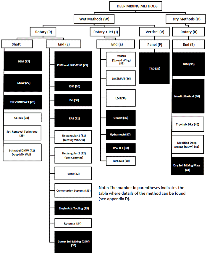
FHWA researchers developed a classification system based on construction parameters including binder type, mixing mechanics, and location of the mixing tool.(1) The classification has been expanded to include additional variants of DMM that have been developed since the original publication, as follows:
Methods currently being used are classified according to this system and shown in figure 137. The methods that have been used in the United States are shown in black boxes. The methods shown in white boxes have been used internationally or experimentally or are still being developed. Method variations are constantly being developed and used. Readers are encouraged to investigate available mixing capabilities beyond the techniques listed in figure 137 to consider new methods and companies not included at the time this report was published.

Figure 137. Flowchart. Classification of vertical axis DMMs based on agent (W/D), penetration/mixing principle (R/J/V), and location of mixing action (S/E/P).(1)
Several other classification systems have been proposed to organize the various and numerous DMM methods according to application and according to deep or shallow mixing. (See references 8, 86, 118, and 126.)
In general, wet mixing methods are single- or multi-shaft wet mixing processes that use primarily cement-based slurries to create isolated elements, continuous walls, or blocks. Shallower mixing may also be conducted to stabilize masses of soil. Wet mixing equipment comprises a batch plant to supply slurry and a mixing machine to inject and mix the slurry into the ground.
Wet mixing methods are used for both offshore and on-land projects. A large portion of offshore projects are conducted in Japan, and these applications are generally outside of the scope of typical U.S. transportation projects. Information on these offshore applications is provided by CDIT.(46)
The slurry batch plant typically includes silos, a water tank, a batching system, temporary storage tanks, slurry pumps with flowmeters, and power supply units. A typical batch plant layout for a larger project is shown in figure 138. Plant components may be simple or complex depending on the requirements of the project and may vary from manually or computer-controlled colloidal shear mixers to a sophisticated in-line jet mixing system.(118) Storage tanks contain paddle agitators to maintain binder disbursement throughout the slurry. Pumps are typically duplex or triplex reciprocating piston pumps or variable speed progressive cavity pumps with rates of ranging from 0.1 to 0.3 yd3/min (0.08 to 0.25 m3/min) and up to 1.3 yd3/min (1 m3/min) for high-capacity mixing tools.

Source: Hayward Baker Inc.
Figure 138. Photo. Slurry batching plant for larger mixing project.
Three levels of sophistication of process control may be defined for batching and injection parameters as follows:(3)
Although various levels of process control are routinely used, automated batching systems are recommended to measure the water, cement, and other additives by weight to produce slurry with uniform properties.(9) These systems allow the desired weight of each slurry component to be preset and mix design changes to be made by adjusting the component at the control panel.
Wet mixing methods are classified in four general categories as shown in table 20 (see figure 137).
Table 20. Typical equipment and common applications for the four general classifications of wet mixing methods.
Classification |
General Equipment and Process |
Common Applications |
|---|---|---|
Wet rotary shaft (WRS) |
Single or multiple shaft equipment with blades over a length of the shaft that mechanically mix injected slurry with surrounding soil |
Columns, panels, or blocks of mixed soil to depth of 98 ft (30 m) |
WRE |
Single shaft equipment with single mixing tool |
Columns, panels, or blocks of mixed soils to depths of 131 ft (40 m) or mass stabilization of large volume to depths up to 49 ft (15 m) |
Wet jet end (WJE) |
Single (uncommon) or multiple shaft equipment tipped with blades and assisted by jetting of slurry through high-pressure ports |
Columns, panels, or blocks of mixed soil to depth of 82 ft (25 m) |
Wet vertical panel (WVP) |
Chainsaw-type vertical cutting tool mounted on a central cutter post |
Continuous walls up to 164 ft (50 m) deep routinely |
In the most commonly used WRS methods for on-land applications, mixing is conducted using vertical hollow rotated mixing shafts supported on a track-mounted crane. One to eight mixing shafts may be used, although two to four are typically used per carrier, depending on the nature of the project, the particular variant of the method, and the contractor. Typical WRS machines are shown in figure 139. The shafts are mounted on fixed or hanging leads and are driven by a top-drive gearbox that distributes the torque from a rotary drive unit to each shaft. Shafts are supported at vertical intervals to keep the mixing tools parallel and maintain accurate vertical control. For multishaft equipment, blades and auger flights on adjacent shafts are staggered. On some machines, the spacing between the shafts may be adjusted to vary the amount of overlap between columns. The drill shafts are often rotated in opposite directions during drilling to enhance mixing efficiency and increase stability of the machine. The direction of rotation of each shaft is often reversed during withdrawal to further improve mixing efficiency. Position and verticality of the shaft may be monitored using optical survey devices or a Global Positioning System (GPS) device. Since fluid is being introduced into the ground, surface spoils can be considerable.

Source: Geo-Con Inc.
Figure 139. Photo. Typical WRS mixing machine.
Each mixing shaft is tipped with a cutting tool below the blades to help control verticality during penetration. Different cutting tools may be used to accommodate drilling through varying soil conditions. The shaft above the cutting tool contains mixing blades, which blend the slurry continuously with the soil during penetration. The distribution and number of mixing blades employed per shaft are dependent on the capacity of the base machine.
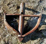
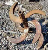
Mixing tools are broadly categorized as blade-based and auger-based.(126) Blade-based tools comprise a series of mixing blades oriented in different directions along the drill shaft. The blades are equipped with cutting teeth that aid penetration. Slurry injection nozzles are located at various intervals along the mixing tool, usually near the tip of the shaft, but can also be positioned along and above the blades.(118) Examples of typical blade-based mixing tools are shown in figure 140 and figure 141.

Figure 140. Photo. Typical blade-based tooling for WRS mixing.(127)

Figure 141. Photo. Second view of typical blade-based tooling for WRS mixing.(127)
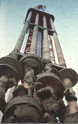
Auger-based mixing tools comprise continuous or discontinuous flight augers or several levels of inclined paddles located along the length of the drill shaft. Slurry injection nozzles are located at the bottom of each shaft. An example of auger-based mixing tools is shown in figure 142.

Source: Geo-Con Inc.
Figure 142. Photo. Typical auger-based tools for WRS methods.
Mixing machine details and typical operational parameters for WRS methods used internationally are summarized in appendix D.
WRE methods are either used for installing deep columns or stabilizing masses of soil to shallower depths. WRE mixing equipment for deep construction on land includes one or two shafts typically 2.3 to 3.3 ft (0.7 to 1.0 m) in diameter (see figure 143). Each shaft has four to six mixing blades. The maximum depth of construction is up to 131 ft (40 m).

Source: Raito, Inc.
Figure 143. Photo. WRE mixing equipment.
WRE mixing equipment for shallow soil stabilization typically includes one shaft tipped with a generally large-diameter single cutting tool (see figure 144 and figure 145). The cutting tool serves as both the drilling bit and mixing tool and is supported by a hollow stem kelly bar on a large track-mounted crane. With some methods, the shaft may be attached rigidly to the base unit, allowing down pressure to be applied during mixing. Because of torque limitations, the drilling depth of the single-auger system is typically limited to 50 ft (15 m).(9) When used in conjunction with an onsite batching and delivery plant, the expected production can be up to 785 yd3 (600 m3) per rig per 8-h shift.

Source: Hayward Baker Inc.
Figure 144. Photo. Typical tools used for WRE mixing.

Source: TREVIICOS Corporation
Figure 145. Photo. Second view of typical tools used for WRE mixing.
The CSM method is a WRE method that is differentiated from other rotary end methods because the cutting blades move vertically by rotating about horizontal axes (see figure 146). This method was developed from diaphragm wall technology and uses two sets of counter-rotating vertically mounted cutter wheels. The wheels cut the surrounding soil and concurrently blend the injected slurry with the soil to form panels 1.7 to 4 ft (0.55 to 1.2 m) wide. Panels are installed in a primary-secondary sequence to create continuous walls. The speed and direction of rotation for each cutting wheel are controlled and monitored separately, allowing for assurance of overlap between panels. Wheels may be equipped with rock teeth to help cut through difficult soils, including cobbles up to 8 inches (200 mm) in diameter or bedrock with up to 7,250 psi (50 MPa) unconfined compressive strength. DMM elements installed into bedrock may be needed to key in cutoff walls for seepage control applications or provide additional shear resistance.

Source: Malcolm Drilling Inc.
Figure 146. Photo. CSM method cutter wheels.
WJE methods combine mechanical mixing and high-energy slurry injection to reduce penetration resistance and enhance mixing efficiency. These methods are differentiated from conventional jet grouting, which does not employ mechanical mixing to create the treated material. Single- and multi-shaft equipment is used. Slurry is injected through high-velocity ports located at the bottom of the shaft and at the outer edges of the mixing blades (see figure 147). Water is injected during penetration of the shaft, and slurry is injected during withdrawal to enhance mixing efficiency. The soil is mixed mechanically at the shaft near the center of the tool, and unmixed lumps are forced to the perimeter of the column to be broken up by the jetted water and air. Air may also be injected during penetration or withdrawal for mixing of stiff soils or to increase column diameter. For some systems (e.g., Hydramech system), the jets may be turned on and off to allow plugs of treated soil to be created.

Figure 147. Photo. Example of a WJE tool.(127)
For the GeoJet™ system, jetting and mechanical mixing are both used during penetration to increase the speed of tool advancement; however, only mixing is used during withdrawal. The process is controlled by computer, and adjustments to operational parameters may be made automatically in response to changing subsurface conditions. Production rates are typically very high for this system.
The original wet mixing classification has been expanded to include a recently developed system classified as WVP.(1) The system is a Japanese development known as TRD. The TRD mixing process employs a vertically mounted chainsaw-type cutting tool with simultaneous slurry injection. The chain with cutting teeth rotates about a central vertical cutter post, and slurry is simultaneously injected to mix with the disturbed soil (see figure 148 and figure 149). The cutter post is inserted into the ground with injection and mixing to the target depth, and the injection and mixing continue as the post is moved horizontally to create a continuous wall of mixed soil. This method has been used to install walls up to 98 ft (30 m) deep in the United States. Walls 197 ft (60 m) deep have been reported in Japan.

Source: Geosystems, L.P.
Figure 148. Photo. TRD tooling.

Source: Geosystems, L.P.
Figure 149. Photo. Second view of TRD tooling.
Dry mixing methods are typically single-auger techniques that primarily use lime, cement, or slag mixtures to create isolated columns, walls, or blocks for soil stabilization and reinforcement. Dry mixing equipment comprises a binder mixing and preparation system and a mixing machine. Two main types of dry mixing techniques are used and referred to as the Japanese dry jet mixing (DJM) method and the Nordic method (also referred to as the lime or lime-cement column method).
The DJM binder injection system comprises a stationary or movable binder storage/premixing and supply unit. The equipment components consist of silos with binders, a pressurized tank with a binder feeder system, a high-capacity air compressor, an air dryer, a filter unit, a generator, a control unit, and connecting hoses.(118) A typical dry binder handling system is shown in figure 150.

Source: Hayward Baker Inc.
Figure 150. Photo. Typical binder delivery unit for dry mixing.
In the traditional Nordic system, the lime and cement are provided from separate tanks and are mixed in a closed-system tank, eliminating the risk of dust leakage during installation. There is a dryer on the compressor (to prevent hydration of the binder) and a sieve/filter. The tanks are equipped with load cells to measure weights of binder material injected. In a more recently developed version of the system, two units are used: an installer and a carrier. The carrier contains tanks and a compressor and is in radio contact with the installer. The carrier is operated from the installer, both of which are crawler-mounted.
The mixing tools are located at the end of the mixing shaft as opposed to along the length of the shaft for wet mixing equipment, so all of the methods are classified as DRE methods. DJM mixing machines are usually equipped with two mixing shafts but may use only one shaft to accommodate narrow or low headroom working areas. The base equipment comprises custom-built, crawler-mounted, or (rarely) skid-mounted cranes. The mixing system consists of the drive unit, the drive shaft, the cutting and mixing blade, and grout nozzles. The rotation motors and gear boxes are permanently located near the base of the rig, effectively lowering the center of gravity and improving stability when tracking on uneven ground.
The mixing unit comprises two or three pairs of blades mounted on each of the shafts offset 90 degrees to each other (see figure 151 and figure 152). The standard blade is 3 ft (1 m) in diameter, and the maximum depth is 108 ft (33 m). The heavy rotation motors and gear boxes are positioned at the bottom of the mast promoting mechanical stability. Construction parameters (depth, revolutions per minute, penetration and withdrawal rates, and volume of binder) are monitored continuously and automatically.

Figure 151. Photo. Typical mixing tool for DRE methods.(118)

Figure 152. Photo. Typical mixing tool for DRE methods for peat mixing.(118)
Binder is injected using compressed air to prevent choking of the nozzles. Upon reaching the bottom depth of the element, the unit is counter-rotated and withdrawn while dry materials are injected under compressed air from nozzles located in the upper mixing blade. Some binder may also be injected during penetration, but more commonly, injection occurs only during withdrawal. The shape of the mixing blades causes a cavity to be created beneath the blade during rotation. As the cavity is created, air pressure within drops and dry reagent is deposited. The compressed air used to deposit the dry materials passes upward along the shaft and vents through a valve in the particle collection shroud located at the ground surface. Because injected materials are dry, surface spoils are minimal.
In the Nordic method, the base equipment is a crawler-mounted self-contained rig that rotates a tool to target depth (typically less than or equal to 82 ft (25 m)). Rods may be square in section and rotated from the bottom or round in section and rotated with a top drive. Square rods permit air to escape from the ground more easily during drilling. Columns between 1.6 and 4 ft (0.5 and 1.2 m) may be installed. A column diameter of 2 ft (0.6 m) remains the most common, although 2.6 ft (0.80 m) is also popular, especially in the United States.
In the Nordic method, compressed air is introduced during penetration to break up the soil structure and keep the injection ports clear. Dry materials are then pneumatically delivered as the tool is rotated in the opposite direction and withdrawn. The pressure of the compressed air is reduced as the tool nears the surface, while the air typically discharges to the surface around the drill rod from all depths. The computer system provides real-time control of the processes (especially rate of materials injected), as well as records of quantities of materials, rate of injection, revolutions per minute, withdrawal rate, air pressure, binder material composition, and depth. The verticality of the drill is automatically controlled to within ±0.25 degree.
Instantaneous penetration rates are about 6 inches (150 mm)/rotation during penetration (varies with the soil) and 0.6 inches (15 mm)/rotation on withdrawal. A 49-ft (15 m)-long column can be installed in 5 min. Industrial production of 1,300 to 3,300 ft (400 to 1,000 m) per 8-h shift for 2-ft (0.6-m)-diameter columns (146 to 366 yd3/shift (112 to 280 m3/shift)) is common and is dictated by the type of soil, amount of binder, and column diameter.
Combination methods are also available, such as the modified deep mixing (MDM) method, which has the capability of switching between dry binder and water injection at specific depths. This versatility allows efficient mixing of layered strata or in response to site-specific project needs or localized changes in subsurface moisture conditions.
Another variant to the conventional DRE method is the mass stabilization method called Dry Soil Mixing. The process is different from other DRE methods because the mixing blades rotate vertically about a horizontal axis to churn the upper several feet of ground, creating a block of stabilized soil (see figure 153).

Source: Hayward Baker Inc.
Figure 153. Photo. Horizontal mixing tool for mass soil stabilization.
The quality of mixed material is dependent on a number of installation parameters including the injection method, the tool rotation and penetration speeds, and the geometry of the mixing tools. A full description of the effect of operational parameters on mixing quality is provided by CDIT.(46)
Injection typically proceeds in the following two manners:
With penetration injection, mechanical mixing is aided by the injection of either slurry or compressed air. At the target depth, rotation may be maintained for several minutes to enhance mixing at the contact between the column and the bearing layer. This process is known as "bottom mixing." Partial or even full restroking of the column length may be conducted by raising and lowering the rotating tools to enhance mixing efficiency, especially in layered materials. The tool is then counter-rotated, and additional slurry or binder is injected during withdrawal, usually in smaller quantities to minimize surface spoils.
Withdrawal injection is commonly used with dry methods, but penetration injection may also be used if the binder quantity required to meet the design strength exceeds that which may be injected during withdrawal alone.
The tool rotation and penetration speeds affect the strength of the treated soil. Studies indicate that higher treated soil strengths are measured from samples produced with higher rotation speeds and lower penetration rates.(46) Comparing the effectiveness of different mixing methods can be subjective because the various mixing techniques and soil conditions produce different mixing results. A simplified index, BRN, has been suggested to quantify the effect of the number of rotations of the mixing blades on the quality of treated soil.(46) BRN is defined as the total number of rotations during 1 m of penetration (downstroke) or withdrawal (upstroke) after the binder has been fed into the ground. BRN is expressed as shown in figure 154.(128)
Where:Study results indicate that a smaller coefficient of variation may be expected when BRN is higher than 360 for the wet method of mixing. This analysis was developed for and is effective only for traditional DMM (not CSM, TRD, or mass stabilization methods).
The number of shafts, the shape and orientation of the mixing blades, and the position of the injection nozzles all influence the quality of the mixed material. Models and field observations indicate that multiple-shaft arrangements generally provide better uniformity of DMM columns than single-shaft systems with fixed cutting/mixing blades rotating in one direction.(46) Adjacent shafts are typically rotated in opposite directions to enhance mixing and increase stability of the machine.
Various orientations and shapes of mixing tools have been developed to meet the requirements of the soils in different regions. Generally, the tools are shaped to disaggregate soil during penetration and increase the degree of mixing with binder upon additional rotation. Soils with peats and plastic clays, for example, require mixing with equipment shaped to deliver a strong shearing action during rotation.
Injection nozzles are positioned to facilitate the type of injection method. For penetration injection, the nozzles are positioned at the base of the tool to lubricate the mixing tool and assist penetration. For jet methods, nozzles are located at the edges of the mixing blades to enlarge column diameters. Nozzles oriented vertically downward are used to increase the penetration rate, and nozzles directed outward from the outer edges of the blades are used to increase the mixing action or diameter of the column